MGC QMP-5101NV User manual

LT-6035 Rev 2 Nov 2014 Page 1 of 7
QMP-5101NV
Network Paging Microphone
Installation Instructions
QMP-5101NV Network Paging Microphone
The QMP-5101NV Network Paging Microphone module fits into the new BBX-FXMNS (MMX-BBX-FXMNS)
Enclosure. It mounts on the inside dead front chassis (part of the BBX-FXMNS [MMX-BBX-FXMNS] door assembly).
Figure 1: QMP-5101NV Network Paging Microphone Module

LT-6035 Rev 2 Nov 2014 Page 2 of 7
Figure 2: BBX-FXMNS Enclosure Complete View
BBX-FXMNS (MMX-BBX-FXMNS)
FRONT DOORS AND DEADFRONT
CHASSIS
BBX-FXMNS
(MMX-FXMNS) BACKBOX
QMP-5101NV Network
Paging Microphone
Mount the QMP-5101NV onto the
inner dead front chassis using the
eleven #6 HEX nuts provided.

LT-6035 Rev 2 Nov 2014 Page 3 of 7
QMP-5101NV Network Paging Microphone Module
The QMP-5101NV Network Paging Microphone Module connects via a ribbon cable to the first QAZT-5302 Zoned
Selector Panel and to the previous display module. It also has wiring terminals for connection to the ANC-5000 Audio
Network Controller Module in the cabinet.
Slide-in labels NP-6659 are placed so that push buttons and LEDs are labelled as shown in Figure 3.
Figure 3: QMP-5101NV Network Paging Microphone Module

LT-6035 Rev 2 Nov 2014 Page 4 of 7
Connect ribbon cable from P1 (IN) to previous display module. Connect P2 (OUT) to the QAZT-5302 Zoned Selector
Panel or next display module. Wire the positive and negative terminals and the microphone MIC positive, negative
and shield to the ANC-5000 Audio Network Controller Module corresponding terminals.
Figure 4: QMP-5101NV Network Master Paging Control Module Connections and
Terminal Blocks
The interface wiring between the QMP-5101NV and ANC-5000 is as follows:
The maximum wiring run from the QMP-5101NV and the ANC-5000 is 20 feet or 6 metres.
MIC+, MIC-, SHLD: 18-22 AWG Twisted Shielded Pair
PTT+, PTT-: 18-22 AWG Twisted Pair
TO QAZT-5302 SELECTOR PANEL
OR NEXT DISPLAY MODULE
CABLE CONNECTS TO PREVIOUS DISPLAY MODULE
TO ANC-5000
PTT + AND -
TERMINALS.
TO ANC-5000
MIC + , SHIELD
AND - OF MIC
TERMNALS.
P1
P2
MIC
ACTIVE
LED

LT-6035 Rev 2 Nov 2014 Page 5 of 7
QMP-5101NV Network Paging Microphone Wiring
Figure 5: QMP-5101NV Network Paging Microphone Wiring to the ANC-5000 Audio
Network Controller Module
JW7
JW8
+ - + -
S - + S - +
S - +S - + L - +
PAGING BUS MIC
PTT
OUT IN
ANC-5000 Audio Network
Controller Module
QMP-5101N Network
Master Paging Module
+
-
Remote
Power
Input
(24V DC
Regulated
1.7 A max)
Network
Fire Alarm
Aux. Power
Supply
G.A.
Input
IN
RS-485
NOT USED
Wire the Paging Bus to
all other ANC-5000
Audio Network Con-
troller Modules OUT
to IN, see Network Fire
Alarm Manual for
more details.
TWISTED
SHIELDED
PAIR CABLE
Jumpers JW7 and JW8
are normally installed
(shorted).
This connection to Aux
Power is required when
the ANC-5000 is
mounted over an
FX-2009-12N/DS
(MMX-2009-12N/DS)
Fire Alarm board.

LT-6035 Rev 2 Nov 2014 Page 6 of 7
Paging Operation
This section describes the controls and indicators on the QMP-5101NV Master Paging and QAZT-5302 Paging
Selector Modules.
QMP-5101NV LEDs
Warden Page
Illuminates steady green to indicate that the Warden Page function is active.
All Call
Illuminates steady green to indicate that the All-Call function is active.
MIC Active LED
Flashes green to indicate any activity on the paging bus (i.e. other microphone in use). Illuminates steady green when
associated microphone (at proximity of LED) is in use.
Pre-Tone Active LED
Steady green when paging and warden paging.
Amplifier Trouble LED
Indicates any amplifier internal trouble.
Mic Trouble LED
Flashes amber to indicate a microphone trouble.
Page to Evac LED
Illuminates steady green when the Page to Evac pushbutton is active.
Page to Alert LED
Illuminates steady green when the Page to Alert pushbutton is active.
AC ON LED
This green LED illuminates steadily to Indicate that AC power is present.
Page Ready LED
Illuminates steady green when the push-to-talk (PTT) on the microphone is depressed (active).
Lamp Test LED
This amber LED illuminates steadily to indicate that the Lamp Test has been activated.
QMP-5101NV Pushbutton Controls
Warden Page Button
When pressed, the Warden Page button enables voice paging from the firefighters' telephone (if connected) to all
zones selected for paging, unless page inhibit is active. Note that pressing PTT will not result in any paging activity
unless there are zones selected for paging. Also note that there must be an active firefighters' telephone connection
for warden paging to occur.
All-Call Button
Selects all zones for voice paging.
All-Call Minus Button
Inverts the selection of zones for voice paging.

LT-6035 Rev 2 Nov 2014 Page 7 of 7
Page to Evac
Pressing this button selects all the audio zones currently in evacuation mode, for paging.
Page to Alert
Pressing this button selects all the audio zones currently in alert mode, for paging.
Page Cancel
Pressing this button de-selects all zones (including those manually selected) from paging.
Lamp Test Button
Momentarily activates all LED indicators.
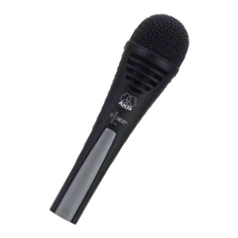
Microphone PTT Button
The microphone's PTT (push-to-talk) button is located on the microphone itself. When depressed, allows voice paging
(from the microphone) to be enabled to all zones selected for paging, unless page cancel is active. Note that pressing
PTT will not result in any paging activity unless there are zones selected for paging.
Table of contents
