MGF IHC150 User manual

mgf.co.uk
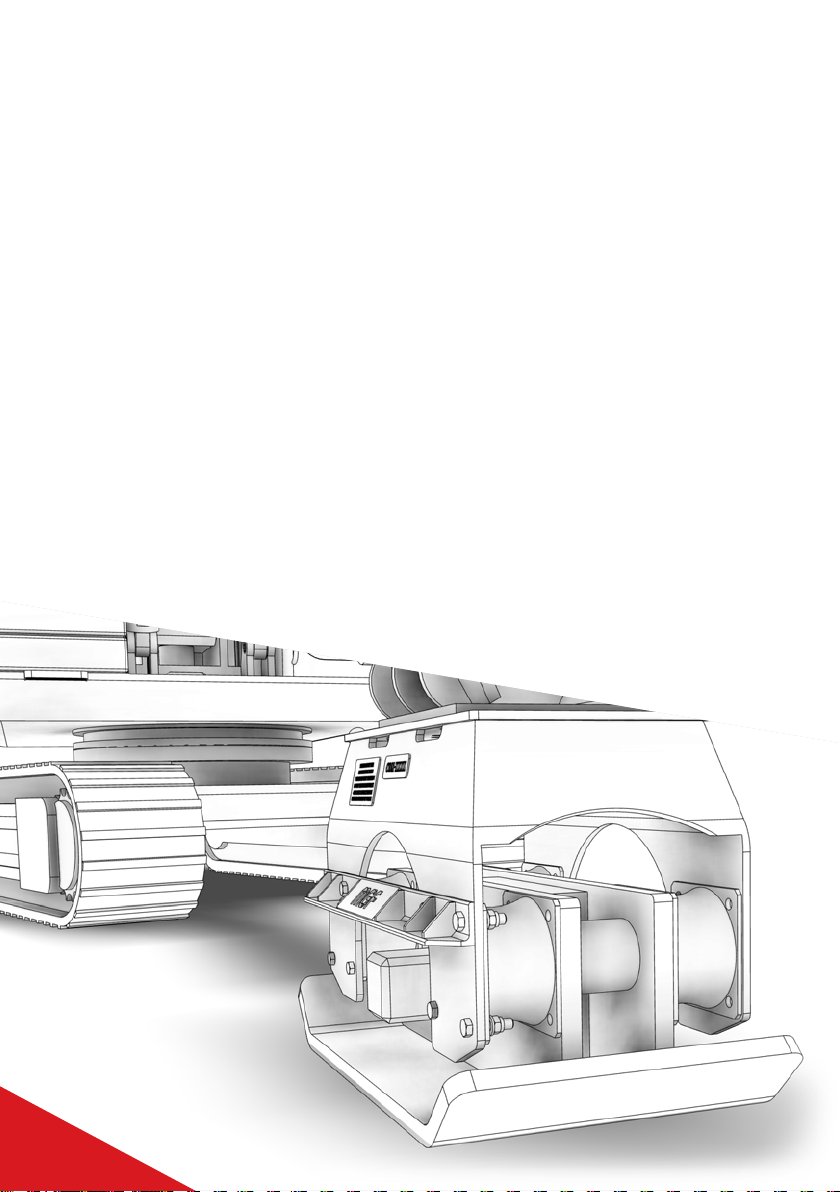
EXCAVATOR
MOUNTED COMPACTOR
IHC150 MODEL
CREATING SAFE WORKING ENVIRONMENTS
With 40 years of experience, MGF is a privately-owned company whose primary focus is the
provision of fully engineered excavation support solutions to the civil engineering, construction,
rail and utilities sectors. We combine technical expertise and operational performance to ensure
the highest levels of customer service. With a focus on developing and promoting industry
best practice in excavation safety we aim to assist our customers in creating safe working
environments for their employees.
CUSTOMER SERVICE AND SUPPORT
The hire and sale of our products is fully supported by our team of qualified engineers,
experienced Technical Sales Representatives, hire desk and operational staff. Our hire centres
provide the focal point for service delivery where our hire desk team will be pleased to receive
your enquiry.
DELIVERY CAPABILITIES
Our dedicated fleet of vehicles offer a flexible solution to quickly meet our customers delivery
needs throughout the UK. We partner with several global shipping companies to ensure we can
quickly deliver our products on a global scale.
CREATING SAFE
WORKING ENVIRONMENTS
2

CONTENTS
SECTION 1: INTRODUCTION 4
SECTION 2: TECHNICAL DATA 5
SECTION 3: PARTS DESCRIPTION / IDENTIFICATION 6
SECTION 4: COMPONENT WEIGHTS & DIMENSIONS 7
SECTION 5: RISK ASSESSMENT CHECKLIST 8
SECTION 6: DO’S / DON’TS 9
SECTION 7: COMPACTOR OPERATION 11
7.1 DELIVERY
7.2 CONNECTING TO THE COMPACTOR VIA AN EXCAVATOR QUICK HITCH
7.3 CONNECTING THE HYDRAULIC LINES
7.4 PREUSE CHECKS
7.5 OPERATING INSTRUCTIONS
7.6 GENERAL ADVISE / INSTRUCTIONS
SECTION 8: MAINTENANCE 16
SECTION 9: CHECKS / FREQUENCY OF CHECKS 16
SECTION 10: STEPS TO ATTEMPT RELEASE OF
HYDRAULIC PRESSURE IN ‘PECKER CIRCUIT’ OF
AN EXCAVATOR 17
ISSUE 1
USER GUIDE
EXCAVATOR MOUNTED COMPACTOR

Excavator mounted compactors (also named compaction plates) can be used to provide
safe, fast, efficient compaction for surfaces including soil sand gravel hardcore or recycled
materials.
In addition to open areas, they can also be used within excavations and on embankments.
They can be used to drive in piles or formwork.
They work quickly and economically and are easy for even inexperienced operators to use.
There are many safety benefits to using an Excavator Mounted Compactor Plate as they can
be operated remotely completely removing humans from hazardous area.
Areas of use include:
• Floor levelling
• Soil compaction
• Trench compaction
• Foundation pile driving
• Compaction around pillars
• Guard rail driving
• Asphalt repair
• Maintenance work
INTRODUCTION
4
USER GUIDE SECTION 1
EXCAVATOR MOUNTED COMPACTOR
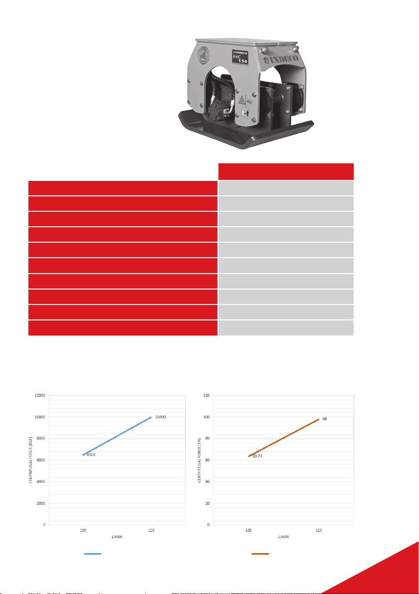
IHC150
Excavator Range 8 to 22 Tons
Equipment Weight 970 Kg
Height 790mm
Baseplate size 710 x 1200mm
Centrifugal Force 10’000 Kgf (98 KN)
Compacting Force 1.8 Kg/cm2(17.7 N/cm2)
Frequency 2000 rpm 33hz
Oil Flow to motor 120 L/min
Max Working Pressure adjusted to the excavator 200 bar
Max Backpressure 21 bar
Note: Weights stated above do not include QH connection bracket.
TECHNICAL
DATA
IHC150 CENTRIFUGAL FORCE VS FLOW IN
IHC150 IHC150
5
USER GUIDE SECTION 2
EXCAVATOR MOUNTED COMPACTOR

03
01
02
09
05
07
08
04
10
06
PARTS DESCRIPTION
/ IDENTIFICATION
01 Quick Hitch Connection Bracket
02 Compactor
03 Motor Impact Guard
04 Hydraulic Connections (on compactor)
05 Elastomer Block – or – Cushion Plate
06 Transport Skid (compatible with 7t – 15t Forklift)
07 Alternate size QH Bracket Pins (IHC 150 only – Ø65 & Ø80 pin options provided)
08 Spare QH Pin – Locking Bar
09 4 x Lift Point (suitable for – MGF Std Duty 4 Leg Chain)
10 4 x Ratchet Strap attachment points – see blue lines in image above for strap pathway
Each Lift point (4 total) has
1.0 Tonne WLL (FOS 6.0)
6
USER GUIDE SECTION 3
EXCAVATOR MOUNTED COMPACTOR
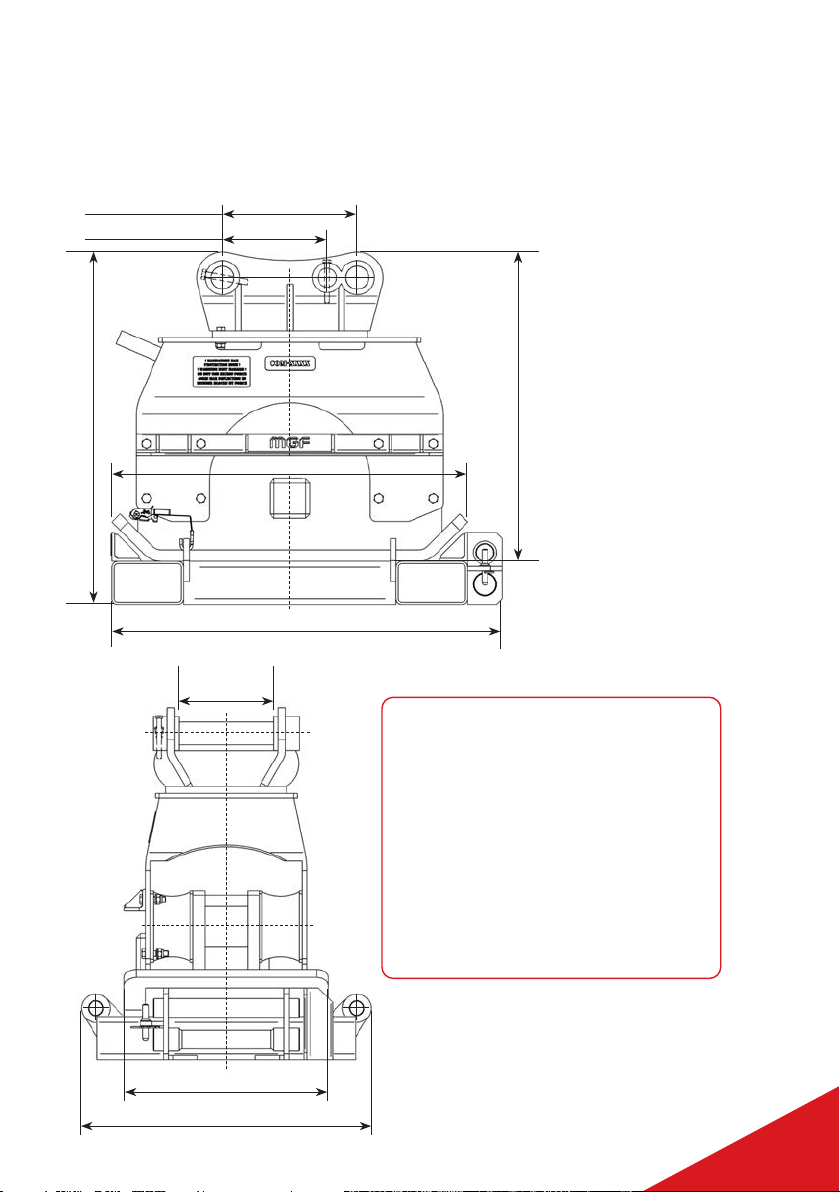
COMPONENT WEIGHTS
& DIMENSIONS
1360
1230 max height (on transport skid)
1080 max height (not on skid)
1240
470 (Ø80 pin centres)
365 (Ø65 pin centres)
1010 - max transport with skid
710 - compactor plate width
330 - max QH
frame width
IHC150 WEIGHTS:
• Compactor IHC150 = 800kg
• Quick Hitch Connection Bracket
(with 2 pins fitted) = 190kg
• Spare Pins (2off) = 30kg total (15kg ea)
• Carry Frame = 208kg
• Max In-Use Weight Total (no skid) =
1000kg
• Max Transport Weight Total (with skid 7
spare pins) = 1230kg
7
USER GUIDE SECTION 4
EXCAVATOR MOUNTED COMPACTOR

RISK ASSESSMENT CHECKLIST
• Consult manufacturers manuals before use of any equipment / plant if in doubt
• Ensure a pre-hire checklist has been completed
• All site activity must be thoroughly planned before work commences to identify hazards
and assess risks
• Ensure that a site/task specific Risk Assessment/Method Statement has been prepared
prior to use
• Ensure that lifting operations have been appropriately planned prior to use
• Ensure that all associated equipment is of sound condition, rated appropriately and is
tested in accordance with legislative requirements
• Ensure that Temporary Works Coordinators (TWC) and Temporary Works Supervisors
(TWS) have been consulted prior to operations commencing
• For any non standard applications (or if application in doubt) - a suitably qualified
engineer should be consulted for approval
• Ensure appropriate PPE is specified and worn. This should include both eye and ear
protection, in addition to other PPE required by site
• Ensure all personnel are properly briefed and adequately supervised by a competent
person(s)
• Ensure control measures are in place for the protection of operatives, third parties, plant
and structures in the proximity of operations prior to them commencing
• Any excavator fitted with a compactor should only be operated from stable ground
• Ensure any overhead cable hazards and associated risks are identified and controlled
• Ensure that regular checks are carried out to ensure that hazards are controlled and the
equipment is in good working order
• Ground vibrations may lead to substantial nuisance or hazard to the adjoining areas.
*MGF Ground Vibration Monitors are available for hire.
• Improper use of the compactor can lead to dangerous situations
CONSIDER THE FOLLOWING WHEN PREPARING YOUR RAMS
The following list is not exhaustive:
• Have all relevant persons been consulted prior to operations commencing
• The selection of competent fitters and operatives and slinger/bankspersons
• Items that could fall from height
• High pressure fluid injection
• Overturning of plant/equipment
• Proximity of operatives
• Third parties and plant in proximity of operations
• Trapping/impact and other mechanical hazards
• Heat from compactor when in use and post use
• Proximity of overhead cables and underground services
• Ground conditions
• Flying Stone chips/etc – due to compaction
• Environmental impacts
8
USER GUIDE SECTION 5
EXCAVATOR MOUNTED COMPACTOR

DO’S/DON’TS
DO’S:
Wear appropriate safety equipment
Only operate the compactor if you are suitably qualified and competent to do so
Ensure the excavator has sufficient load (tonnage) capacity for the compactor
being used
Ensure the quick hitch is fully locked and all hydraulic connections are secure
and leak free
Set up and enforce an ‘Exclusion Zone’
Complete all the required weekly, daily and pre-use checks and report any
defects
Ensure there is always visual contact between the operator and any operatives
near operations
Monitor the compactor operation constantly, interrupt the process immediately
if there are operational issues or any dangerous (or suspected dangerous)
situation occurs
Follow the agreed (and briefed) safe system of work/RAMS
Be aware of any buried services (gas water pipes - or electric cable)
Use the compactor flat to the surface being compacted
Store the compactor in a safe clean area, on or with its transport skid when not
in use
Place compactor onto transport skid and fit ratchet straps when ready for re-
collection
Have hydraulic spill kits available (can be sourced from MGF) before
commencing works
Employ Safe manual handling techniques where applicable
9
USER GUIDE SECTION 6
EXCAVATOR MOUNTED COMPACTOR

DONT’S:
Do not operate the compactor if anyone is in the exclusion zone
Do not enter the ‘Exclusion Zone’ if the compactor is being operated
Do not use the compactor if it is faulty in any way
Do not touch the compactor during the operating process (even if the excavator
is switched off) as it can become hot
Do not over compact and this can lead to services damage. If in doubt STOP and
consult relevant engineers
Do not submerge the compactor in water or operate submerged
Do not obscure the ‘line of sight’ of the operator
Do not use excessive force to disconnect quick release couplings, if they will not
disconnect by normal force they likely have pressure trapped within them. (see
section 8). Do not use levers or tools to force fittings apart as this can result in
damage/charges and could lead to operatives being sprayed by forced hot oil
Do not re-use nyloc nuts on vibration equipment, use a new part when
re-fitting
Do not put yourself or other in danger of falling from the excavator or
equipment during fitting or use
Do not operate the compactor whilst moving the excavator or travelling across
site
Do not position or pass the compactor above or over operatives. No one should
ever be under the compactor even whilst moving position
Do not expose operatives to danger of ‘Working at Height’ - when connecting
or disconnecting hoses. Always lower and position the excavator stick arm to
assist and minimise working from height
10
USER GUIDE SECTION 6
EXCAVATOR MOUNTED COMPACTOR

COMPACTOR OPERATION
7.1 DELIVERY
The compactor will be supplied on a transport skid. Choose an area where the skid can be
left and the compactor can be placed when not in use. It is suggested to move the skid to
this area.
If moving the skid at any point the ratchet straps must always be used and secured.
(For IHC150 only) the compactor will be supplied with a Quick Hitch bracket that can have
either Ø65 or Ø80 pin options fitted.
Pre-hire the customer can specify which size connection is preferred and MGF will supply
the compactor in this configuration. The Quick Hitch bracket is inspected as per LOLER
pre-hire, but this inspection is void if customer changes configuration themselves.
Whichever pin size is not fitted the spare pins are secured to and located on the transport
skid.
If the customer wishes they can swap the pin configuration, but this is done at their own
risk and they are entirely responsible for any misfitting outcomes, with no liability to MGF.
65 PIN CONFIG*** 80 PIN CONFIG**
***Note: Rear pin in 65 configuration is dog bone shaped - inner section is Ø65, with two outer
Ø80 sections for where it engages in bracket.
**Note: Rear pin in 80 config is a pin Ø80 across its full length.
Note: Each pin must be secured to Quick Hitch bracket - via 2 off M20 bolts and 2 off (unused
before fitting) M20 Nyloc nuts.
Failure to correctly secure pins could result in equipment falling from the excavator during
use.
Pins not being used should be stored in the purpose made area on the transport skid and
secured using the locking pin.
Remove ratchet straps and the compactor can either be lifted from the skid using slings
securely passed through/around the compactors quick hitch pins - or the excavator can
connect to the QH bracket, and once locked to the excavator quick hitch the compactor can
be moved or lifted via that connection.
11
USER GUIDE SECTION 7
EXCAVATOR MOUNTED COMPACTOR

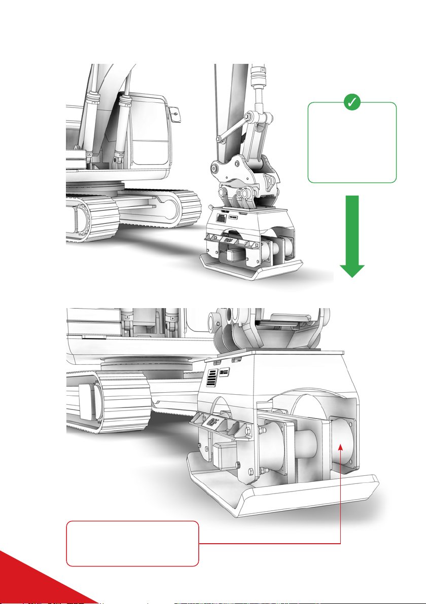
7.2 CONNECTING TO THE COMPACTOR VIA AN EXCAVATOR
QUICK HITCH
If a bucket is attached, remove from the Quick Hitch coupler by following the relevant
manufacturer’s instructions.
Place the dipper arm to ground level and shut down the excavator prior to connecting the
hydraulic auxiliary pipes to the connectors.
Engage the coupler to the pins and curl/crowd the coupler.
If using a fully automatic Quick Hitch, continue to fully curl/crowd the head. Switch to the
‘attach’ or ‘on’ position: the buzzer will cease. Hold the crowd lever for approximately 5 -
10 seconds to allow the hook to fully engage and clamp.
Note: For use of other types of Quick Hitch, refer to the relevant manufacturer’s instructions.
BEFORE OPERATING THE MACHINE, THE OPERATOR SHOULD EXIT THE
CAB AND, FROM A SAFE AREA, PERFORM A VISUAL CHECK TO ENSURE
THE HOOK HAS FULLY ENGAGED THE PINS.
7.3 CONNECTING THE HYDRAULIC LINES
IT IS ADVISED THAT THE COMPACTOR SHOULD BE FITTED BY AN MGF
SERVICE ENGINEER MAKING THE NECESSARY HOSE CONNECTIONS
AND CHECKING FOR FULL FUNCTIONALITY. THE COMPACTOR SHOULD
ONLY BE OPERATED BY SUITABLY TRAINED PERSONNEL.
SAFETY NOTES
• Extreme care and adequate precautions must always be taken to
prevent trapping fingers during connections or disconnections
• Do not use excessive force to disconnect quick release couplings - if they will not
disconnect by normal force they likely have pressure trapped within them. (See
section 8) - do not use levers or tools to force fittings apart as this can result in
damage/charges and could lead to operatives being sprayed by pressured hot oil.
• Ensure the compactor is only ever fitted to uni-directional flow systems,
unrestricted back to tank
• An MGF fitter will set up and identify hoses – by putting RED PVC tape around
the ‘flow in’ designated hose on the compactor. Red tape around also around
the excavator flow out QR fitting. Operatives can just match ‘red - to - red’ when
connecting
• The compactor will be fitted with TWO Male QR fittings - flow in to be identified by
red PVC tape. (Image right shows In - Out orientation of Compactor - ref for fitters)
• Excavator will be checked to have/or adapted to have TWO Female QRS fittings -
flow out identified by red PVC tape
12
USER GUIDE SECTION 7
EXCAVATOR MOUNTED COMPACTOR

7.4 PREUSE CHECKS
When all installation works are completed, check the following before operating the
compactor.
While moving the excavator’s bucket cylinder slowly in and out in the direction of ‘crowd’
and ‘dump’, check:
For any interference or obstruction between the compactor and excavator
Whether the length of the connecting hoses are too short or too long
For any twisting, excessive bending or squeezing of the connecting hoses
The fixing status of the mounting pins
While lifting the compactor above the ground (no-loading condition), check:
Whether the compactor runs normally without delay when the operating switch is
pressed ON, and that it stops when OFF
For any oil leaks from hoses, fittings, hydraulic motor or motor control valve
For loosening of bolts or nuts
For cracking or tears in the elastomers
If any abnormal vibration or noise occurs while the compactor is running
In – Out orientation of Compactor – ref for fitters
HVFK050F000
Manifold
Out
In
Return Hose
Pressure Hose
In
Out
A
B
13
USER GUIDE SECTION 7
EXCAVATOR MOUNTED COMPACTOR
7.5 OPERATING INSTRUCTIONS
Press down in a
direction vertical
to the ground, with
compactor plate
angled to match
ground angle.
Whilst applying force, elastomer
blocks must not deform/stretch
by more than 40mm.
14
USER GUIDE SECTION 7
EXCAVATOR MOUNTED COMPACTOR

Max deflection = half original elastomer diameter
• Place the compactor uniformly on the ground you want to compact
• Lower the excavator’s boom slowly to press the compactor vertically to the ground
Ensure that the Elastomer Block is deformed/stretched less than 40mm. If the
Elastomer Block is pressed more than the specified limit, it may be damaged or its life
might be shortened
• If you operate the compactor, having touched a very hard object such as a concrete floor
or bedrock, it would apply a very high impact which may result in a serious damage
• When the ground starts to be lowered by compacting, lower the excavator’s boom
gradually and keep a constant applying pressure: ensure the elastomer block is not
excessively stretched/deformed
• When compacting a wide area, advance working positions sequentially in a uniform
direction with some overlapped area
• For normal soil condition, recommended working time is 5 - 10 seconds. Operating
continuously for long periods will not improve compacting and may result in damage to
the compactor
7.6 GENERAL ADVISE/INSTRUCTIONS
• Keep Compactor Plate level to the floor/ground being compacted and apply a vertical
force
• Do not use the compactor as a breaker - or use it to push heavy items or plant onsite
• Do not support the excavator with the compactor - i.e. jack the excavator off the floor
• Do not apply excessive force
• Do not use the compactor for crane work or use to lift or pull objects
• Do not use underwater or submerge the compactor in water
• Temperature range for compactor oil - max 180F/82°C, min temp is 32°F/0°C. Idle the
excavator till warm and operate compactor unloaded if below min temperature
• Groundworkers should wear masks/filters and any other appropriate PPE if dust an
issue, or use dampening if an option
15
USER GUIDE SECTION 7
EXCAVATOR MOUNTED COMPACTOR

MAINTENANCE
SERVICING AND MAINTENANCE OF COMPACTORS TO BE CARRIED OUT BY
MGF ONLY. DO NOT ATTEMPT TO CARRY OUT MAINTENANCE OR REPAIRS.
IHC150 = Reservoir Capacity = 4.8L (85/90W Gear Oil)
CHECKS / FREQUENCY
OF CHECKS
DAILY:
Check Quick Hitch connecting bracket for loose cracked or missing bolts (this is both
mounting bolts, and pin securing bolts)
Examine hydraulic hoses for leaking or signs of excessive abrasion
Visually inspect compactor for any signs of damage
Check hydraulic hose quick release fitting for secure fix or any signs or leakage
Check return line connection - if it becomes restricted or pinched motor failure/
damage charges could occur
WEEKLY:
Check fasteners for tightness. Any replacement fasteners must be the same size
specification and grade as originals
Inspect Elastomer Blocks for signs of tearing, or damage
Check oil level in Compactor reservoir
(To check oil level - remove 3/8” NPT plug from side of oil reservoir on the base plate
assembly of the compactor. Operating oil level should be flush with the bottom of the
plug hole)
16
USER GUIDE SECTION 8 & 9
EXCAVATOR MOUNTED COMPACTOR

STEPS TO ATTEMPT
RELEASE OF HYDRAULIC
PRESSURE IN ‘PECKER
CIRCUIT’ OF AN EXCAVATOR
ISSUE = WHEN ATTEMPTING TO RELEASE OR USE THE ‘QUICK RELEASE’
COUPLINGS OF THE COMPACTOR FROM AN EXCAVATOR ‘PECKER
CIRCUIT’, PRESSURE CAN BE TRAPPED IN THE CIRCUIT WHICH MEANS
THE QUICK RELEASE COUPLINGS ARE VERY HARD TO OPERATE, OR
CANNOT BE OPERATED DUE TO THE PRESSURE.
Turn the key back on
to ‘ignition’ stage,
but do not start the
engine.
2
Turn off the excavator
engine using the
ignition key.
1
17
USER GUIDE SECTION 10
EXCAVATOR MOUNTED COMPACTOR

Ensure the dead man
switch (usually a lever at
the side of the operator’s
seat) is up or enabled.
3
Drop or disable the dead man control
lever, then turn machines ignition ‘off’.
Pressure can be confirmed to be released,
as quick release couplings should
rotate relative to each other freely and
disconnect easily.
Dead man’s lever shown in the
dropped or disabled position
(machine controls off). Position can
vary dependant on machine.
5
Do not operate or move
the joysticks or other
controls, but carefully
move only the control
switch for the pecker
circuit. This should be
switched several times.
It is likely you will hear
a click as pressure
releases, and physically
see the taut pressurised
hoses sag as pressure
releases.
4
Do not move any
controls other than the
pecker control switch.
Move left and right. Note: On this machine pecker
circuit control was on right
stick thumb control. It can vary
from machine to machine.
18
USER GUIDE SECTION 10
EXCAVATOR MOUNTED COMPACTOR

WHAT IS HAPPENING BY THESE ACTIONS?
Modern excavators have a pressure accumulator built into them. This can be thought of as
a small capacity hydraulic battery.
What we are doing with the above steps, is to use the hydraulic power in the accumulator,
to open or move the spool in the pecker circuit, which releases the pressure in the
hydraulic line.
PROBLEM SOLVING
If experiencing issues with releasing the pressure:
a. Repeat the above steps several times
b. Complete the steps within approx. a 30 second period. (reason - accumulator pressure
can drop over time due to wear or seal leakage. A newer machine will give you more
time to complete the steps etc.)
If pressure cannot be released by this method contact an MGF fitter.
19
USER GUIDE SECTION 10
EXCAVATOR MOUNTED COMPACTOR

EXCAVATOR MOUNTED COMPACTOR
NOTES
20
Table of contents


