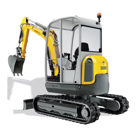
Wacker Neuson 28Z3 User manual

Service Manual
Track excavator
Machine model 28Z3
Edition 2.0
Language en
Article number 1000178347

Documentation
Description Language Order no.
Operator's Manual en 1000177367
Service manual en 1000178347
Spare parts list de/en/fr 1000177410
Spare parts list de/it/es 1000177471
Copyright – 2011 Wacker Neuson Linz GmbH, Linz-Leonding
Printed in Austria
All rights reserved
No part of this publication may be reproduced, translated or used in any form or by any means – graphic, electronic
or mechanical including photocopying, recording, taping or information storage or retrieval systems – without prior
permission in writing from the manufacturer.
The cover features the machine with possible optional equipment.
Wacker Neuson Linz GmbH
Haidfeldstr. 37
A-4060 Linz-Leonding
Document: SHB 28Z3 EN
Order no.: 1000178347
Edition: 2.0
Legend
Edition Issued
1.0 5/2008
2.0 12/2011

SHB 28Z3 EN - Edition 2.0 * 28Z3s20IVZ.fm I-1
ITable of contents
Operation
Notices on this service manual ................................................................................ 1-2
Identification of warnings and dangers .................................................................... 1-3
Designated use and exemption from liability ........................................................... 1-4
Type labels and component numbers ...................................................................... 1-5
Machine overview .................................................................................................... 1-8
Cab overview ........................................................................................................... 1-9
Cab (legend) .......................................................................................................... 1-10
Instrument panel overview ..................................................................................... 1-11
Instrument panel legend ........................................................................................ 1-12
Overview of open engine and valve compartment ................................................. 1-12
Engine compartment: overview ............................................................................. 1-13
Chassis overview ................................................................................................... 1-14
Valve compartment ................................................................................................ 1-15
Stop and park the machine .................................................................................... 1-16
Parking the machine on slopes ....................................................................... 1-16
Specifications
Chassis .................................................................................................................... 2-2
Engine ...................................................................................................................... 2-2
Fuel injection pump ........................................................................................... 2-2
Engine capacities .............................................................................................. 2-3
Engine tightening torques .................................................................................. 2-3
Hydraulic system ..................................................................................................... 2-3
Work hydraulics ................................................................................................. 2-3
Auxiliary hydraulics oil flow 28Z3 ....................................................................... 2-4
Undercarriage and swivel unit ................................................................................. 2-4
Stabiliser blade ........................................................................................................ 2-4
Electrical system ...................................................................................................... 2-4
Noise levels ............................................................................................................. 2-5
Vibration ................................................................................................................... 2-5
Coolant compound table .......................................................................................... 2-5
Powertilt ................................................................................................................... 2-5
Model-specific tightening torques ............................................................................ 2-6
General tightening torques ...................................................................................... 2-6
Tightening torques for hydraulic screw connections (dry assembly) ................. 2-6
Tightening torques for high-resistance screw connections ................................ 2-8
Dimensions model 28Z3 ........................................................................................ 2-10
Dimensions model 28Z3 VDS ................................................................................ 2-11
Lift capacity table 28Z3 (short stick) ...................................................................... 2-13
Lift capacity table 28Z3 long stick (option) ............................................................. 2-14
Lift capacity table 28Z3 short stick and extra weight (option) ................................ 2-15
Lift capacity table 28Z3 long stick (option) and extra weight (option) .................... 2-16
Lift capacity table 28Z3 VDS (short stick) .............................................................. 2-17
Lift capacity table 28Z3 long stick VDS (option) .................................................... 2-18
Kinematics ............................................................................................................. 2-19
Maintenance
Fluids and lubricants ................................................................................................ 3-2
Oil grades for the diesel engine, depending on temperature ............................. 3-3
Additional oil change and filter replacement (hydraulic system) ........................ 3-3
Oil grades for the hydraulic system, depending on temperature ....................... 3-4
Maintenance label .................................................................................................... 3-5

I-2 SHB 28Z3 EN - Edition 2.0 * 28Z3s20IVZ.fm
Explanation of symbols on the maintenance label ............................................. 3-5
Maintenance plan (overview) ................................................................................... 3-7
Service package .................................................................................................... 3-11
Introduction ............................................................................................................ 3-11
Safety-relevant parts .............................................................................................. 3-11
Fuel system ............................................................................................................ 3-12
Refuelling ......................................................................................................... 3-13
Emptying the fuel tank ..................................................................................... 3-13
Stationary fuel pumps ...................................................................................... 3-14
Diesel fuel specification ................................................................................... 3-14
Bleeding the fuel system .................................................................................. 3-14
Water separator ............................................................................................... 3-15
Replacing the fuel filter .................................................................................... 3-16
Tank for washer system ................................................................................... 3-16
Engine lubrication system ...................................................................................... 3-17
Checking the oil level ....................................................................................... 3-17
Filling up engine oil .......................................................................................... 3-18
Changing engine oil ......................................................................................... 3-19
Replacing the engine oil filter cartridge ............................................................ 3-20
Engine and hydraulics cooling system ................................................................... 3-21
Specific safety instructions .............................................................................. 3-21
Checking/filling up coolant ............................................................................... 3-22
Checking the coolant level ............................................................................... 3-22
Filling up coolant .............................................................................................. 3-23
Draining coolant ............................................................................................... 3-23
Air filter ................................................................................................................... 3-24
Replacing air filter elements ............................................................................ 3-24
Air intake .......................................................................................................... 3-26
Change cab air filter ............................................................................................... 3-27
V-belt ...................................................................................................................... 3-28
Checking V-belt tension ................................................................................... 3-28
Retightening the V-belt .................................................................................... 3-29
Pressure check ...................................................................................................... 3-31
General ............................................................................................................ 3-31
Overview of measuring ports (up to serial number AG02712) ......................... 3-31
Overview of measuring ports (from serial number AG02713) ......................... 3-31
Checking pilot control pressure ....................................................................... 3-32
Pressure check of variable displacement pump P1 ......................................... 3-33
Pressure check of variable displacement pump P2 ......................................... 3-34
Pressure check of gear pump P3 .................................................................... 3-35
Secondary pressure limiting valve of the gear motor ....................................... 3-36
Primary pressure limiting valves ...................................................................... 3-36
Test report ............................................................................................................. 3-37
Hydraulic system .................................................................................................... 3-41
Specific safety instructions .............................................................................. 3-41
Checking the hydraulic oil level ....................................................................... 3-42
Filling up hydraulic oil ...................................................................................... 3-43
Changing hydraulic oil ..................................................................................... 3-44
Monitoring the hydraulic oil return filter ............................................................ 3-44
Replacing the hydraulic oil filter ....................................................................... 3-45
Draining condensation water from the hydraulic oil tank ................................. 3-45
Important information for the use of biodegradable oil .................................... 3-46
Checking hydraulic pressure lines ................................................................... 3-47
Pilot valve ............................................................................................................... 3-48
Travelling drive ....................................................................................................... 3-49
Checking the oil level and filling up oil ............................................................. 3-49

SHB 28Z3 EN - Edition 2.0 * 28Z3s20IVZ.fm I-3
Draining oil ....................................................................................................... 3-49

Tracks .................................................................................................................... 3-50
Checking track tension .................................................................................... 3-50
Adjusting track tension .................................................................................... 3-51
Maintenance of attachments .................................................................................. 3-52
Lubrication points ................................................................................................... 3-52
Parking the machine ........................................................................................ 3-52
Overview of lubrication points ................................................................................ 3-53
Lubrication points on the stabiliser blade and stabiliser blade ram ................. 3-54
Lubrication points on the swivelling console and slewing ram ........................ 3-54
Lubrication points on the boom, bucket and stick rams ................................... 3-55
Lubrication points on the boom and stick ........................................................ 3-56
Lubrication point on the joint rod ..................................................................... 3-56
Lubrication point on ball bearing race of live ring ............................................ 3-57
Lubrication point of live ring teeth .................................................................... 3-57
Lubrication point of VDS live ring teeth ........................................................... 3-58
VDS lubrication points (option) ........................................................................ 3-59
Powertilt lubrication points (option) .................................................................. 3-59
Lubrication points of hydraulic quickhitch (option) ........................................... 3-60
Lubrication points of mechanical quickhitch (option) ....................................... 3-60
Cab ........................................................................................................................ 3-60
Electrical system .................................................................................................... 3-61
Service and maintenance work at regular intervals ......................................... 3-61
Instructions concerning specific components .................................................. 3-61
Alternator ......................................................................................................... 3-61
Battery ............................................................................................................. 3-62
General maintenance work .................................................................................... 3-63
Cleaning .......................................................................................................... 3-63
General instructions for all areas of the machine ............................................ 3-63
Inside the cab .................................................................................................. 3-63
Cleaning the seat belt ...................................................................................... 3-63
Exterior of the machine .................................................................................... 3-64
Engine compartment ....................................................................................... 3-64
Shatter protection ............................................................................................ 3-64
Screw connections and attachments ............................................................... 3-64
Pivots and hinges ............................................................................................ 3-64
Preparatory work before taking out of service ....................................................... 3-65
Maintenance if the machine is out of service for a longer period of time ............... 3-65
Putting into operation again ............................................................................. 3-65
Fire extinguisher .................................................................................................... 3-66
Engine
3TNV76-NNS engine overview ................................................................................ 4-2
Fuel system ............................................................................................................. 4-4
Cooling system ........................................................................................................ 4-5
Checking and adjusting valve clearance ................................................................. 4-6
Lapping the intake and exhaust valves ............................................................. 4-7
Tightening order for cylinder head bolts .................................................................. 4-7
Order for removing the cylinder-head bolts: ...................................................... 4-7
Order for mounting the cylinder-head bolts: ...................................................... 4-7
Checking the injection nozzles ................................................................................ 4-8
Pressure check .................................................................................................. 4-8
Checking the nozzle jet ............................................................................................ 4-9
Injection time ............................................................................................................ 4-9
Checking injection time ...................................................................................... 4-9
Setting injection time ....................................................................................... 4-11
Removing and installing the injection pump .......................................................... 4-12

I-4 SHB 28Z3 EN - Edition 2.0 * 28Z3s20IVZ.fm
Removing the injection pump .......................................................................... 4-12
Fitting the injection pump ................................................................................. 4-13
Measuring and adjusting the engine speed ........................................................... 4-14
Compression .......................................................................................................... 4-14
Checking the coolant thermostat ........................................................................... 4-15
Checking the thermal switch .................................................................................. 4-15
Oil pressure switch ................................................................................................. 4-16
Checking the coolant circuit ................................................................................... 4-16
Cleaning the cooling water channels ..................................................................... 4-16
Coolant and fuel hoses .......................................................................................... 4-16
Crankcase vent ...................................................................................................... 4-17
Replacing the glow plugs ....................................................................................... 4-17
Engine trouble ........................................................................................................ 4-18
Hydraulic system
Hydraulic pump PVD-0B-23BP-8G3-5083A ............................................................ 5-2
Pump unit: exploded view .................................................................................. 5-4
Pilot oil supply unit ............................................................................................. 5-5
Dismantling the hydraulic pump ......................................................................... 5-6
Assembling the hydraulic pump ......................................................................... 5-8
Troubleshooting on the hydraulic pump ........................................................... 5-12
Main valve block .................................................................................................... 5-13
Ports ................................................................................................................ 5-13
Main control lines (legend) ............................................................................... 5-14
Pump/tank lines ............................................................................................... 5-14
Main valve block diagram ................................................................................ 5-15
Pressure limiting valves ................................................................................... 5-16
Pump assignment ............................................................................................ 5-17
Drive counterbalancing system .............................................................................. 5-18
Pump assignment for drive counterbalancing .................................................. 5-18
Regeneration – stick section .................................................................................. 5-19
Bucket pre-tension ................................................................................................. 5-19
Auxiliary hydraulics flow rate adjustment ............................................................... 5-20
Travelling drive ....................................................................................................... 5-21
Function ........................................................................................................... 5-22
Swivel unit .............................................................................................................. 5-24
Swivel unit brake .............................................................................................. 5-25
Swivel joint ............................................................................................................. 5-27
Replace the sealing rings ................................................................................ 5-27
Swivel joint VDS (option) ....................................................................................... 5-28
Pilot valves ............................................................................................................. 5-29
Joystick ............................................................................................................ 5-29
Pilot valve (driving) .......................................................................................... 5-30
Changeover valve for SAE/ISO controls (option) ................................................... 5-32
Proportional valve (option) ..................................................................................... 5-32
Changeover valve VDS (option) ............................................................................ 5-33
3/2 directional valve (option) .................................................................................. 5-33
Easy Lock valve (option) ........................................................................................ 5-33
Hydraulic oil tank service valve (option) ................................................................. 5-34
Breather filter ......................................................................................................... 5-34
Auxiliary hydraulics connections ............................................................................ 5-35
Troubleshooting in the hydraulic system ................................................................ 5-36
Hydraulics diagram (legend) .................................................................................. 5-38
Hydraulics diagram 28Z3 ....................................................................................... 5-39
Hydraulics diagram for options 28Z3 ..................................................................... 5-40
Main valve block diagram 28Z3 ............................................................................. 5-41

SHB 28Z3 EN - Edition 2.0 * 28Z3s20IVZ.fm I-5
Electrical system
Ohm's Law (current, voltage, resistance); power ..................................................... 6-2
Measuring equipment, measuring methods ............................................................. 6-2
Cable colour coding ................................................................................................. 6-3
Relays ...................................................................................................................... 6-3
Use, mode of function ........................................................................................ 6-3
Socket ...................................................................................................................... 6-4
Electric units ............................................................................................................ 6-4
Fuse box .................................................................................................................. 6-4
Alternator ................................................................................................................. 6-5
Starter ...................................................................................................................... 6-5
Switches: overview .................................................................................................. 6-6
Switch legend .................................................................................................... 6-6
Cigarette lighter ....................................................................................................... 6-7
Radio and mounting/wiring for radio installation (option) ......................................... 6-7
Front working light ................................................................................................... 6-8
Cab lights (option) .................................................................................................... 6-8
Rotating beacon (option) ......................................................................................... 6-9
Driving signal (option) .............................................................................................. 6-9
Wiring diagram (legend) ........................................................................................ 6-12
Wiring diagram ....................................................................................................... 6-13
Engine/chassis wiring harness (legend) ................................................................ 6-16
Chassis/engine wiring harness .............................................................................. 6-18
Cab wiring harness ................................................................................................ 6-19
Proportional controls wiring harness (option) ........................................................ 6-20
Engine speed control wiring harness (option) ........................................................ 6-21
Driving signal wiring harness (option) .................................................................... 6-22
Hydraulic quickhitch wiring harness (option) ......................................................... 6-23
Battery lead ............................................................................................................ 6-24
Options
Counterweight .......................................................................................................... 7-2
Specifications .................................................................................................... 7-2
Long stick ................................................................................................................. 7-2
Specifications .................................................................................................... 7-2
Automatic engine speed setting ............................................................................... 7-3
Installation ......................................................................................................... 7-4
Grab pipework ......................................................................................................... 7-5
Attachments ....................................................................................................... 7-5
3rd control circuit/PowerTilt ports ............................................................................ 7-6
Safe load indicator ................................................................................................... 7-7
Safe load indicator DE (from serial no. AG04828) (safety valves for boom) ........... 7-8
Safe load indicator DE (serial nos. AG02444 to AG04827) (safety valves for boom)
7-9
Safe load indicator DE (up to serial no. AG02443) .......................................... 7-10
Function ........................................................................................................... 7-10
Wiring diagram ................................................................................................ 7-11
Setting the pressure switch ............................................................................. 7-11
Safe load indicator FR (from serial no. AG04828) (safety valves for boom, stick and sta-
biliser blade) .......................................................................................................... 7-12
Safe load indicator FR (serial nos. AG02444 to AG04827) (safety valves for boom,
stick and stabiliser blade)
......................................................................................................................... 7-13
Safe load indicator FR (up to serial no. AG02443) .......................................... 7-14
Function ........................................................................................................... 7-14
Diagram (from serial no. AG04828) ................................................................. 7-15
Diagram (serial nos. AG02444 to AG04827) ................................................... 7-16

I-6 SHB 28Z3 EN - Edition 2.0 * 28Z3s20IVZ.fm
Diagram (up to serial no. AG02443) ................................................................ 7-16
Setting the pressure switch .............................................................................. 7-17
Hose burst valve safety feature ............................................................................. 7-18
Mechanical quickhitch ............................................................................................ 7-19
Hydraulic quickhitch (Easy Lock) ........................................................................... 7-20
3rd control circuit .................................................................................................... 7-20
Function ........................................................................................................... 7-20
Diagram ........................................................................................................... 7-20
Drive interlock (antitheft protection) ....................................................................... 7-21
Position ............................................................................................................ 7-21
Disabling the drive interlock ............................................................................. 7-21
Enabling the drive interlock .............................................................................. 7-21
Programming ................................................................................................... 7-21
Proportional controls .............................................................................................. 7-23
Function ........................................................................................................... 7-23
Ports ................................................................................................................ 7-24
Measures to be taken in case of malfunctions ................................................. 7-24
Left-hand control lever ..................................................................................... 7-24
Boom swivel controls ....................................................................................... 7-25
Auxiliary hydraulics .......................................................................................... 7-25
Hammer operation ........................................................................................... 7-25
Adjusting control response .............................................................................. 7-26
Characteristic curves – status indicator ........................................................... 7-26
Wiring harness ................................................................................................. 7-27
Control unit connector assignment .................................................................. 7-27
Measures to be taken in case of malfunctions ................................................. 7-28
Diagnosis display ............................................................................................. 7-28
Engine oil service valve ......................................................................................... 7-29
Function ........................................................................................................... 7-29
PowerTilt PTS06
General instructions ................................................................................................. 8-2
General safety instructions ................................................................................ 8-2
Checking the product ......................................................................................... 8-3
Internal decompression valve ............................................................................ 8-3
Testing the hydraulic system of the machine ..................................................... 8-3
Specifications/requirements ............................................................................... 8-4
Tools ........................................................................................................................ 8-5
Making a tool VI for removing the seals ............................................................. 8-6
Separating the bucket or equipment from the PowerTilt swivel device .................... 8-6
Separating the PowerTilt swivel device from the machine ....................................... 8-6
Exploded views PTS06 ............................................................................................ 8-7
PTS06 components ........................................................................................... 8-7
Sealing kit A and bearing kit B PTS06 (overview) ............................................. 8-8
Assembly drawing .................................................................................................... 8-9
Removing the standard journal coupling ................................................................ 8-10
Removing the end cap, securing ring and internal decompression valve .............. 8-12
Removing the shaft ................................................................................................ 8-13
Removing the piston tube body ............................................................................. 8-14
Removing the seals (kit A), shaft bearings and pressure discs (kit B) ................... 8-15
Checking components and dead centre marks ...................................................... 8-16
Trial assembly ........................................................................................................ 8-17
Installing the seals (kit A), shaft bearings and pressure discs (kit B) ..................... 8-17
Installing the end-cap seals and bearings ....................................................... 8-18
Installing the piston seals and bearings ........................................................... 8-19

SHB 28Z3 EN - Edition 2.0 * 28Z3s20IVZ.fm I-7
Fitting the shaft seal and the bearing .............................................................. 8-20
Installing the piston tube ........................................................................................ 8-21
Installing the shaft .................................................................................................. 8-22
Installing the end cap and the securing ring .......................................................... 8-23
Installing the internal decompression valve ........................................................... 8-24
Installing the standard journal coupling ................................................................. 8-24
Lubrication and tests .............................................................................................. 8-27
Lubrication ....................................................................................................... 8-27
Test for internal leaks ...................................................................................... 8-27
Testing the internal decompression valve ....................................................... 8-28
Securing the PowerTilt swivel device on the machine ........................................... 8-29
Fitting a bucket or equipment onto the PowerTilt swivel device ............................ 8-29
Troubleshooting .................................................................................................... 8-30
Adjusting the play on the PowerTilt ....................................................................... 8-31
Checking the circumferential play .................................................................... 8-31

I-8 SHB 28Z3 EN - Edition 2.0 * 28Z3s20IVZ.fm

Operation

1-2 SHB 28Z3 EN – Edition 2.0 * 28z3s110.fm
Operation
1 Operation
1.1 Notices on this service manual
This service manual contains important information on how to work safely, correctly and
economically with the machine. Therefore, it aims not only at new staff, but it also serves
as a reference for experienced staff. It helps to avoid dangerous situations and reduce
repair costs and downtimes.
Furthermore, the reliability and the service life of the machine will be increased by follow-
ing the instructions in the Operator's Manual.
Careful and prudent working is the best way to avoid accidents!
Operational safety and readiness of the machine do not only depend on your skill, but also
on maintenance and servicing of the machine. This is why regular maintenance and ser-
vice work is absolutely necessary.
Extensive maintenance and repair work must always be carried out by a Wacker Neuson
workshop. Use only original spare parts for repairs. This ensures operational safety and
readiness of your machine, and maintains its value.
•We reserve the right to improve the technical standard of our machines without
adapting the service manual.
•Modifying Wacker Neuson products and fitting them with additional equipment and
attachments not included in our delivery program requires Wacker Neuson's written
authorisation, otherwise warranty and product liability for possible damage caused by
these modifications shall not be applicable.
•Subject to modifications and printing errors.
Your Wacker Neuson dealer will be pleased to answer any further questions regarding the
machine or the service manual.
Abbreviations/symbols
• This symbol stands for a list
• Subdivision within lists or an activity. Follow the steps in the recommended order
☞This symbol requires you to carry out the activity described
➥Description of the effects or results of an activity
n. s. = not shown
A combination of digits, or a combination of digits and letters, e.g. 40/18 or 40/Aused for
identifying the control elements, means:
Figure no. 40/control element no. 18 or position Ain figure no. 40
Figures carry no numbers if they are placed to the left of the text.
Operation

SHB 28Z3 EN – Edition 2.0 * 28z3s110.fm 1-3
Operation
1.2 Identification of warnings and dangers
Important indications regarding the safety of the staff and the machine are identified in this
Service Manual with the following terms and symbols:
Danger!
Failure to observe the instructions identified by this symbol can result in
personal injury or death for the operator or other persons.
☞Measures for avoiding danger
Caution!
Failure to observe the instructions identified by this symbol can result in
damage to the machine.
☞Measures for avoiding danger for the machine
Notice!
This symbol identifies instructions for a more efficient and economical use of
the machine.
Environment!
Failure to observe the instructions identified by this symbol can result in dam-
age to the environment. The environment is in danger if environmentally haz-
ardous material (e.g. waste oil) is not subject to proper use or disposal.

1-4 SHB 28Z3 EN – Edition 2.0 * 28z3s110.fm
Operation
1.3 Designated use and exemption from liability
• The machine is intended for:
• Moving earth, gravel or rubble, and for hammer operation
• See chapter 1.4 “Fields of application, attachments” in the Operator's Manual for
more information on the use of attachments.
• Every other application is regarded as not designated for the use of the machine.
Wacker Neuson will not be liable for damage resulting from use other than mentioned
above. The user alone will bear the risk.
• Designated use also includes observing the instructions set forth in the Operator's Manual
and observing the maintenance and service conditions.
• The safety of the machine can be negatively affected by carrying out machine modifica-
tions without proper authority and by using spare parts, equipment, attachments and
optional equipment which have not been checked and released by Wacker
Neuson GmbH. Wacker Neuson GmbH will not be liable for damage resulting from this.
• Wacker Neuson Linz GmbH shall not be liable for personal injury and/or damage to
property caused by failure to observe the safety instructions and the Operator's
Manual, and by the negligence of the duty to exercise due care when:
• handling
• Operation
• servicing and carrying out maintenance work and
• repairing the machine. This is also applicable in those cases in which special
attention has not been drawn to the duty to exercise due care, in the safety instruc-
tions, the Operator's Manuals and maintenance manuals (machine/engine).
• Read and understand the Operator's Manual before starting up, servicing or repairing
the machine. Observe all safety instructions!
• The machine may not be used for transport jobs on public roads!
• Do not use the machine in areas with danger of falling objects from above or the front.
• The quickhitch is only used for locking an attachment.
• Hammer operation is only allowed in specified areas.

SHB 28Z3 EN – Edition 2.0 * 28z3s110.fm 1-5
Operation
1.4 Type labels and component numbers
Serial number
The serial number is stamped on the machine chassis. It is also located on the type label.
The type label is located at the front left on the machine chassis, under the control stand.
Type label information
Field below Wacker Neuson logo: HYDRAULIC EXCAVATOR
Fahrzeug Seriennummer/serial no./no. de série: Serial number of machine
Fahrzeug Modell/model/modèle: Machine designation
Leistung/performance: Engine output
Typ/version: Machine type
Betriebsgewicht/operating weight/poids en charge: Operating weight
Transportgewicht/transport weight/poids en transport: Transport weight
G. Gew./GWR/PTAC: Gross weight rating (admissible)
Max. Nutzlast/max. payload/max. charge utile: Maximum payload
Zul. Achslast vorne/front GAWR/PNBE AV: Front gross axle weight rating
Zul. Achslast hinten/rear GAWR/PNBE AR: Rear gross axle weight rating
Option
EWG Nr./CEE no.: EEC check number
Baujahr/model year/année fabr.: Year of construction
Other information – see chapter 2 Specifications on page 2-2
Cab number
The type label (arrow) is located on the chassis of the cab, at the upper left beside the
door.
Fig. 1: Type label: location
Fig. 2: Type label
HYDRAULIC EXCAVATOR
Fig. 3: Cab type label

1-6 SHB 28Z3 EN – Edition 2.0 * 28z3s110.fm
Operation
Engine number
The type label (arrow) is located on the valve cover (engine).
Hydraulic pump number
The type label is located on the hydraulic pump housing.
Main valve block number
The type label (arrow) is located on the lower side of the main valve block.
Travelling drive number
The type label (arrow) is located on the travelling drive.
Swivel unit number
The type label (arrow) is located on top of the gear motor.
Fig. 4: Diesel engine number
Fig. 5: Hydraulic pump type label
Fig. 6: Main valve block type label
Fig. 7: Travelling drive type label
Fig. 8: Swivel unit type label

SHB 28Z3 EN – Edition 2.0 * 28z3s110.fm 1-7
Operation
Hydraulic quickhitch
Powertilt with hydraulic quickhitch
The serial number of the Powertilt is stamped in the housing near the hydraulic connec-
tions.
The serial number of the hydraulic quickhitch is located on the type label.
The type label is located at the rear on the hydraulic quickhitch fork.
Type label information (example):
Field below the Wacker Neuson logo: description of components
PIN: part number
Serien Nr./serial no./no. de série: serial number
Gewicht/weight/poids: max. authorised weight
Volumen/volume/volume: max. capacity
für Modell/for model/pour le modèle: for equipment model
Lieferant/supplier/fournisseur: supplier's SAP number
Gewicht/weight/poids: weight of this component
Druck/pressure/pression: max. authorised pressure
Baujahr/model year/année fabr.: year of construction
Norm/standard/norme: standards the component complies with
Not all components require all fields to filled with data.
Other information – see chapter 2 Specifications on page 2-2
Fig. 9: Hydraulic quickhitch type label
Fig. 10: Powertilt type label
Fig. 11: Type label

1-8 SHB 28Z3 EN – Edition 2.0 * 28z3s110.fm
Operation
1.5 Machine overview
Fig. 12: Machine outside views
1 Working light
2 Boom
3 Auxiliary hydraulics
4Stick
5 Handle
6 Stabiliser blade
7Eye hook for loading/tying
down the machine
8 Undercarriage
9 Exhaust pipe
10 Engine cover
11 Rotating beacon
12 Boom light
13 Canopy (standard)/cab (option)
14 Tank filler inlet
15 Valve cover
16 Rubber tracks
17 Lubrication point for track tension
1 2
11
10
9
8
3
4
7 6
11
13
14
15
12
1687
3
17
5
13

SHB 28Z3 EN – Edition 2.0 * 28z3s110.fm 1-9
Operation
1.6 Cab overview
23
24
21
3 4 5 6 9 101
11
13
14
15
16
18
17
28
27
31
32
30
29
33
25
22
20
19
8
34
26
7
12
2

1-10 SHB 28Z3 EN – Edition 2.0 * 28z3s110.fm
Operation
1.7 Cab (legend)
Pos. Designation
1Pedal – swivel boom
2Horizontal seat adjustment
3Drive pedal (left)
4Drive lever (left)
5Drive lever (right)
6Drive pedal (right)
7Document storage (underneath the seat console)
8Hydraulic quickhitch pedal (option)
9Drive interlock emitter/receiver unit (from serial number AG00699)
10 Auxiliary hydraulics pedal
11 Round display element
12 Heating
13 Preheating start switch
14 Control lever (right)
15 Drive interlock status indicator (option) (up to serial number AG00698)
16 Control lever base (right)
17 Stabiliser blade lever
18 Console switch panel
19 Armrest on the right (not shown)
20 Seat (backrest adjustment)
21 Cab switch panel
22 Seat (weight adjustment)
23 Cigarette lighter
24 Radio (option)
25 Drinks/cup holder/storage net
26 Cab bearing
27 Changeover valve for SAE/ISO controls (option)
28 Seat belt (lock)
29 Armrest (left)
30 Throttle
31 Vertical Digging System (VDS) (option)
32 Control lever (left)
33 Control lever base (left)
34 Seat
Other manuals for 28Z3
1
This manual suits for next models
1
Table of contents
Other Wacker Neuson Excavator manuals

Wacker Neuson
Wacker Neuson 50Z3 User manual

Wacker Neuson
Wacker Neuson 50Z3 User manual

Wacker Neuson
Wacker Neuson DW100 User manual

Wacker Neuson
Wacker Neuson 38Z3 User manual

Wacker Neuson
Wacker Neuson 75Z3 User manual

Wacker Neuson
Wacker Neuson EZ38 User manual

Wacker Neuson
Wacker Neuson EZ17 User manual

Wacker Neuson
Wacker Neuson 803 Dualpower User manual

Wacker Neuson
Wacker Neuson 28Z3 User manual

Wacker Neuson
Wacker Neuson 803 Dualpower User manual