MGS HBM 15 User manual

24.11.2014 / V 01.0-EN
1
Reference : Hand-guided Milling Machine
Short Term : HBM 15
Documentation : starting with A0 -015-0001
Operating Manual
Hand-guided Milling Machine
HBM 15

2
24.11.14 / V 01.0-EN
Imprint
Company: MGS –Milling & Grinding –Systems GmbH
Adresse: Schwalbenweg 2
66620 Nonnweiler-Braunshausen
Phone: + 9-(0)6873 / 6690021
Fax.: + 9-(0)6873 / 6690020
Mail: info@mgs-maschinen.de
Mobile: + 9 -(0)160-77 2 3
Internet: www.mgs-maschinen.de
Managing Director: Guido Schnur
Entry in Commercial Register: HRB 101 269 Amtsgericht Saarbrücken
VAT Identification Number: DE 291 965 79
Relevant chamber: Arbeitskammer des Saarlandes

3
24.11.14 / V 01.0-EN
Subjet Page
Front page 1
Imprint 2
Table of content 3
Machine identification number 4
General afety information 5
Specific afety in truction 6
General Information 7
Component and intended u e 8
Technical data 9
Operating 10
Vibration mea urement 14
Duty-cycle 15
Setting and adju tment of bevel ize 16
Standard milling machine 17
Indexable cutting in ert for bevel 22
Indexable cutting in ert for radiu 23
Setting and adju tment of radiu 24
Operating of the machine 26
Schedule of maintenance 28
Service 29
Part li t - gear 33
Part li t - motor 35
Warranty condition 37
EC Declaration of conformity 38
Table of Content
24.11.14 / V 01.0-EN
Machine Identification
Number
Dear cu tomer,
You have decided in favor of a high-quality hand guided bevel milling machine
of type HBM 15, which will enable you to ea ily and rapidly do your beveling
work of a real high quality. To en ure that the machine i u ed afely and pro-
fe ionally we recommend you and your colleague to thoroughly read the e
operating in truction and to make the u er acquainted with the machine.
A careful handling of the machine will prevent accident , reduce co t and im-
prove the quality of your work piece.
Before being packed and delivered to you, the machine ha been clo ely te ted
and checked. In order to be able to help you a fa t and efficient a po ible
we would a k you to kindly indicate the MGS machine identification number
in any ca e.
Thi number i to be found in the upplied operating manual and engraved on
the gearbox flange of the machine.
Machine identification No. : _______________________________
(regi tered)
Gearbox flange
(engraved)
We thank you for u ing our machine and wi h you alway the be t re ult
when working with our machine .
Your MGS –Team

5
24.11.14 / V 01.0-EN
5. General Safety Information
Before u ing the machine, the operating manual and the afety information have to be
read in full and all in truction contained therein have to be followed. Safety in truc-
tion uch a DIN, VDE, CEE, AFNOR and further in truction valid in the country of u e
have to be trictly ob erved.
The e in truction cover the operating and handling of the machine including tool and
acce orie a well a machine maintenance.
Di regarding the e e tabli hed afety recommendation may cau e eriou hazard . It
mu t be garanteed that the machine operator ha clearly under tood the following
recommendation and that he ha acce to them at any time.
The tep given below mu t be taken by the operator in any ca e to avoid improper
handling of the machine or to prevent accident .
In tallation
•
The machine mu t only be connected to the voltage indicated on the machine'
label.
Danger to life from electrocution
•
Before tarting maintenance work di connect the machine from the power
plug. The machine ha to be unplugged and volt-free.
•
Before each u e check plug, cable and machine for ign of damage.
•
The machine mu t be kept dry and not u ed in damp location or humid envi-
ronment .
•
If u ed outdoor, the machine mu t be protected by a re idual-current circuit
breaker with a maximum tripping current of 30.
•
In ert plug only when machine i witched off. Di connect machine from power
plug after u e.
Mandatory working clothes
•
Alway wear afety goggle , ear protection, protective glove and afety hoe
when working with the machine.
•
Wear tight-fitting clothe .
Safety Information

6
24.11.14 / V 01.0-EN
6. Specific Safety Instructions:
Improper use can cause serious injury
•
Don't reach with your hand into working area.
•
Alway hold the machine with two hand .
•
Make ure you alway have a afe po ition when working with the machine.
•
Never touch the milling head when the machine i running.
•
Do not u e the machine for overhead work.
•
The machine hould only be u ed for up-cut milling.
Risk of injury from metal chips
•
Hot chip are ejected from the machine at high peed.
•
U e impact protection.
Risk of injury from ejected indexable inserts
•
U e only original MGS in ert and clamping crew .
•
Tighten the clamp crew with 3 – 4 Nm torque.
Health risk in case of inhaling cutting oil
•
Sufficient venting i e ential for working with cutting oil.
•
Do not inhale ari ing vapor .
Improper use can damage equipment and property
•
Risk of machine being damaged or destroyed.
•
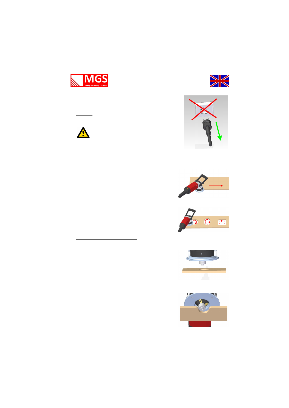
Do not lift or carry the machine by its power cable.
•
Make sure the cable is directed behind and away from the machine.
Do not pull the cable over sharp edges.
•
Servicing and testing must be done by qualified personnel only.
•
Always use original MGS spare parts and accessories.
Safety Information
7
24.11.14 / V 01.0-EN
7. General Handling
a. Security
b. Working Direction
U ing our hand guided milling machine , alway work
again t the direction of rotation of the milling head
('up-cut milling').
Thi mean to ob erve the working direction from
left to right in ca e of plate working tarting in front
at the top
and clockwi e in ca e of working on bore hole or
channel .
c. Bore Diameter or Inner Radius
In order to avoid a hooking of the cutting plate on
tarting the beveling of bore hole , the bore hole
hould alway be at lea t 1.5 fold of the guide
bearing.
In ca e of guide bearing of 45° milling machine the
bore diameter i thu 30 mm x 1.5 = 45 mm.
Con idering ufficient inner radiu for beveling of
inner radiu i al o very important for afe working!
General Information
For all maintenance machine mu t
be di connected from the
power upply y tem!

8
24.11.14 / V 01.0-EN
8. Description of machine
1 Rear handle
2 Speed control
3 Motor
4 Front handle
5 Vernier cale
6 Guide
7 On witch with lock-out feature
8 Milling head with cutting in ert
9 Guide bearing
10 Set ring for height
adju tment
11 Height clamping
12 Height cale
13 Locking button
Intended use:
The hand guided edge milling machine HBM 15 i an electrically powered
machine for the working of work piece made of:
Steel, ca t teel, fine-grained teel, tainle teel,
aluminium, aluminium alloy , bra and pla tic
The machine i de igned for indu trial u e in indu try and mall trade.
• for preparing K, V, X and Y haped welding groove .
• for creating vi ible edge in plant, tool and mechanical engineering
• for edge rounding to prepare material for optimal painting or
• coating or a bump protection.
1 2
5
4
3
6
8
10
9
11
7
12
13
Functional part
Intended u e

9
24.11.14 / V 01.0-EN
9. Technical Data:
Edge Milling Machine
HBM 15
Supply voltage 110 / 230 V
Frequency 50/60 Hz
Input power 1800 W
Idle peed 1500-5600 rpm
Approximate weight 9.9 kg
Bevel width (material dependent)
aluminium 1-15 mm
teel 1-15 mm
tainle teel 1-10 mm
Minimum thickne of work piece 3 mm
Smalle t contour radiu
at 30° 26 mm
at 45° 23 mm
at 60° 27 mm
Smalle t bore diameter
at 30° 39 mm
at 45° 45 mm
at 60° 53 mm
Edge radiu 3— 4 mm
Subject to technical modifications and/or amendments by the manufacturer!
Technical Data
10
24.11.14 / V 01.0-EN
Machine Operation
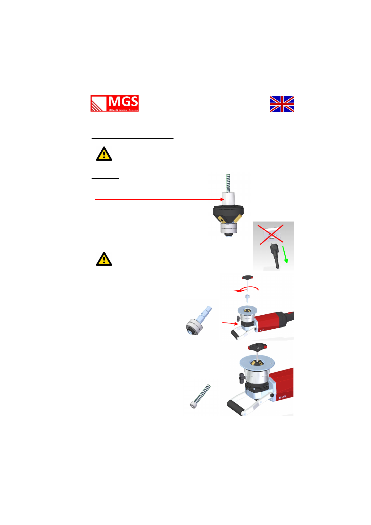
10. Changing the cutting tool
Overheated tools and milling head
Attention: burn hazard!
Alway wear protective glove when changing the cutting tool.
Attention!
A milling head conus is a precision bearing!
In order to prevent it from being damaged
always handle with greatest care.
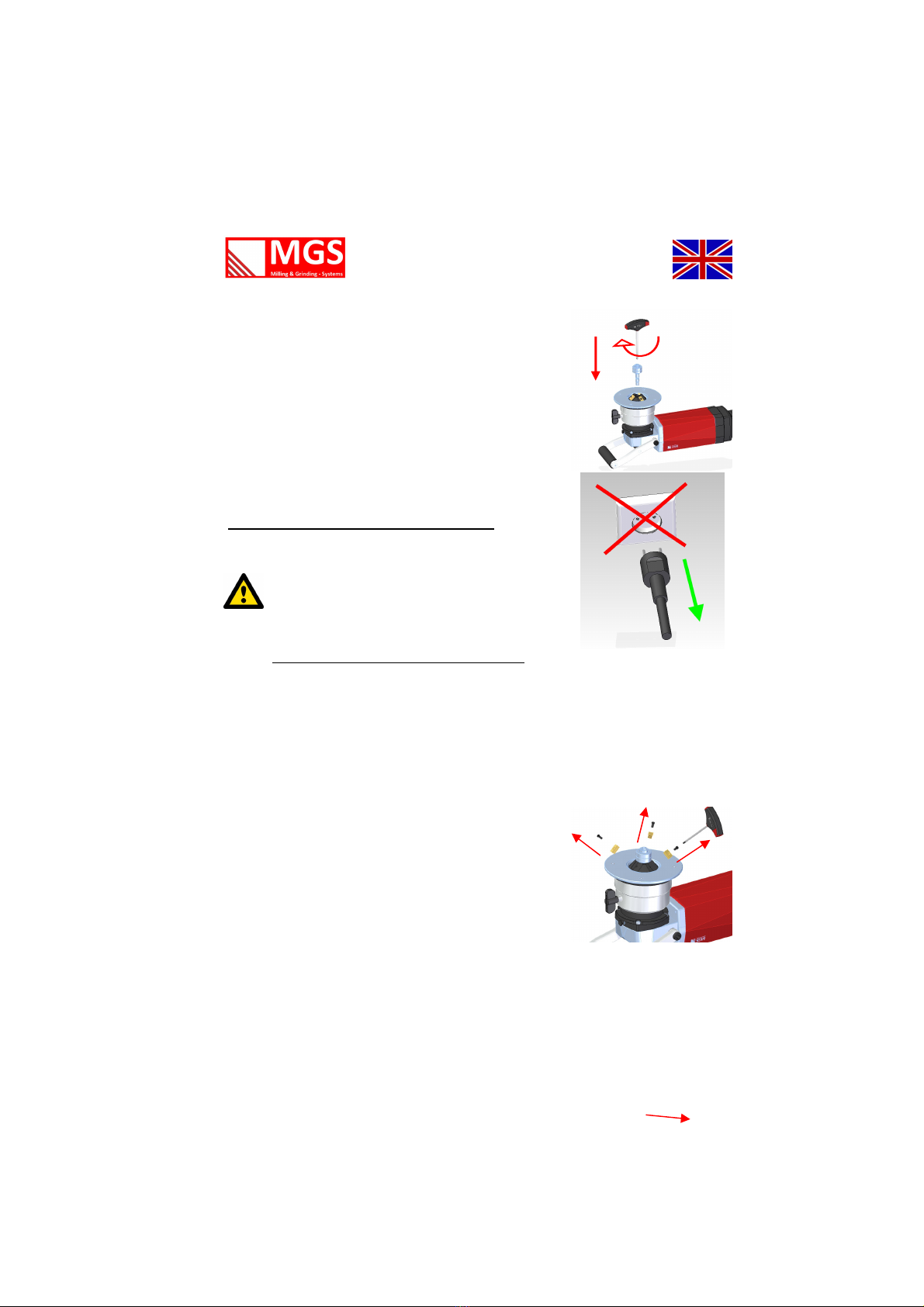
Remove the axi with the guide
bearing by mean of the hex
key SW6 on locking the haft by
the locking button.
Then loo en and remove the ecure
crew of the cutting tool with the
hex key SW5 and take it off.
For all maintenance machine mu t
be di connected from the
power upply y tem!

11
24.11.14 / V 01.0-EN
Operating
Changing the cutting tool
Since the preci ion conu of the cutting tool i a elf-locking conu , that cannot
be loo ened by a mor e taper kindly follow mo t accurately the procedure a
de cribed in the following.
Your machine i provided with an adju table ball ramp to loo en the milling
head.
10 a.
Turn the ball ramp to the milling head „on block“. For
that purpo e put the hex key SW6 a deep into the
milling head (perhap a light crewing up may be
helpful) a nece ary o that the upper marking will
be flu h with the milling head. Sub equently turn the
ball ramp to the left until you can feel a firm re i -
tance. It i po ible that the ball ramp already i
“on block” at the cutting tool, due to the clockwi e
rotation of the drive haft.
10 b.
Now turn the ball ramp to the left until the milling
head i lightly lifted.
10 c.
In order to be able to ea ily take off the milling head,
crew the axi with the bearing into the cutting tool
for one or two turn and u e the axi a a handle to
pull out the milling head.
12
24.11.14 / V 01.0-EN
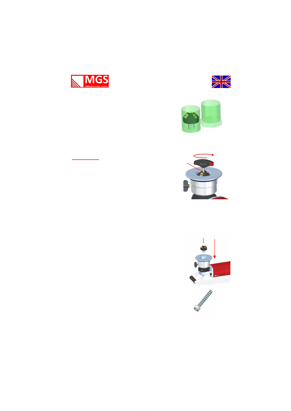
Operating
Put the milling head immediately into the corre-
ponding box to avoid damage to the preci ion
conu .
Al o u e the box for the axi to keep it in afe
cu tody.
Important!!!!
10 d.
To prepare the machine for another new cutting tool,
turn the ball ramp with the hex key SW6 (upper
marking) to the right until it i fixed. Thu the
machine i ready for a change of the milling head.
10 e.
The conu bearing of the haft and the conu hould
be cleaned by dry and lint-free cloth.
Afterward put the new milling head with the conu
into the drive haft and ecure it with the hexagon
bolt (12.9) which you tighten with key SW5.
13
24.11.14 / V 01.0-EN
Operating
10 f.
A a la t tep crew the axi with the guide bearing
belonging to the milling head into the milling head by
u ing the hex key SW6 and your machine i again
ready for operation.
11.Changing the indexable cutting inserts
Property damage caused by blunt tools
Overcharge of the machine!
Regular te ting of tool for abra ion i recommended.
Plea e wear protection glove when changing the
indexable cutting in ert .
In order to change the cutting in ert which can be
u ed with the edge milling machine HBM 15, kindly
proceed a follow :
Place the machine on the upper urface and turn the
guiding plate downward a much a nece ary to get
the cutting in ert totally free o that you can turn
them ea ily or exchange them.
Alway u e a Torx T15.
We recommend to change defective plate or in ert
crew immediately.
To avoid a turning away of the milling tool, lock
the drive haft with the lock button.
For all maintenance machine mu t
be di connected from the power upply
y tem!

1
24.11.14 / V 01.0-EN
Noise Emission
Vibrations
Noise emissions value according to
DIN EN 607 5-1
Vibration:
Wear hearing protection!
Noise emission
Value
Emi ion-noi e level (LPA typically dB (A) 85
Emi ion-noi e level (LWA typically dB (A) 99
Uncertainty
K for Emi ion-noi e level aB 3
Total value of vibration
(Vector sum of three directions)
Unit Value
DIN 6075
Vibration emi ion value ah m/ ² 4
Uncertainty
K for vibration emi ion value m/ ² 1,5
Note: The mea urement were performed on a technically comparable machine
.
Advice:
The above mentioned mea ured value depend on material and application and can therefore be
exceeded.
In ca e bevel wider than admi ible are worked, the value of vibration and noi e are increa ing
to the ame extent.

15
24.11.14 / V 01.0-EN
On-time
We fitted our milling machines with an optimal bearing and a very good lubrication
system. This complex construction which was designed for these extreme applica-
tions, does not prevent damages if the machine is improperly used. To avoid such
damages the indicated on-time should always be respected.
In addition to the high evolution of heat of the electric motor at the tay and at the
magnetic field there i al o more high temperature on milling.
Thi heat i largely di ipated by the metal chip . In ca e of longer la ting, continuou
operation the milling head can get hot on operation which on it turn tran mit the
heat over the drive haft to the cabinet and thu al o on the driving motor.
A great deal of thi heat i di ipated by the ventilator of the electric motor . However,
in ca e of long la ting operation, e pecially on high load due to broad bevel , hard ma-
terial or blunt cutting in ert , thi cooling i no longer ufficient and there i the ri k
that the i olation of the armature winding i damaged which might lead to hort-circuit.
Thu take care that the bevel adju tment i not too high. In ca e of large bevel it i
better to work a bevel in everal troke . Thi al o involve that there i le vibration
leading to le tre on the per on working with the machine, the machine it elf and
the cutting in ert . Blunt in ert increa e vibration. Therefore care for a timely change
of the cutting in ert . Thi preventive mea ure al o con erve your machine.
If the motor i getting too hot it i automatically witched off. Let the motor and the
cabinet cool down o that you can continue your work.
Number of strokes
When milling in everal troke there i le vibration and the cutting in ert are
con erved.
Bevel width
Up to
10mm
Up to
12mm
Up to
15mm
Idle peed
Power-on time
Aluminum, copper,
bra , pla tic
1 1 1 5 60-80%
Steel bi 400N/mm² 1 2 2-3 5 40-60%
Steel bi 600N/mm² 1-2 2 3 6 30-50%
Steel bi 960N/mm² 2-3 3 - 6 20-40%
Stainle teel 2-3 - - 4-5 20-40%
16
24.11.14 / V 01.0-EN
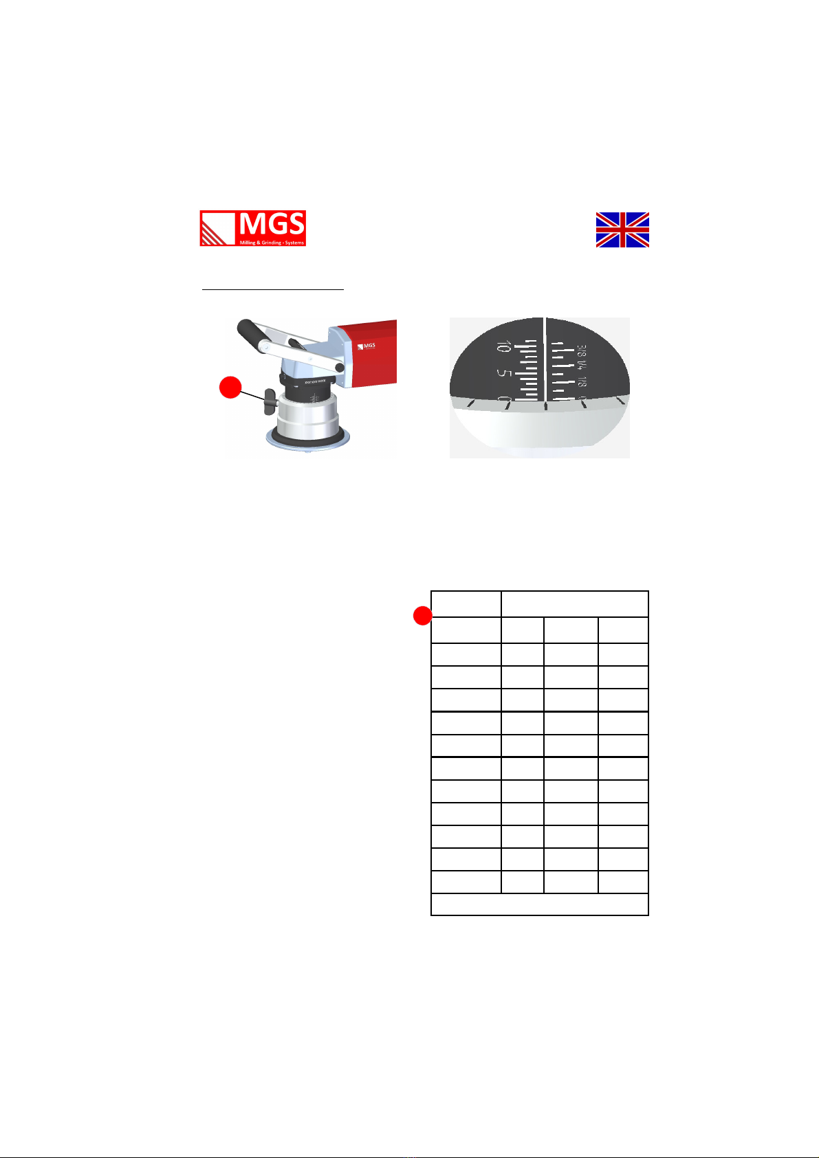
Adju ting the bevel height
16. Machine adju tment
The bevelling ize i determined by the height adju tment of the guide bell and
through the milling head angle
The divi ion of the cale are indicative; the height adju tment of the vernier
arrow to the next arrow i 0.05mm. Thu , you can adju t very preci ely the
hight.
Therefor open the clamp and rotate
the guide bell to the de ired cale level.
Then clo e the clamp and the height
adju tment i complete.
After adju ting cu tomize a ample pie-
ce and check the dimen ion .
Due to manufacturing tolerance a
readju tment may be nece ary.
Bevel width at angle
Bevel height
30° 45° 60°
1 1,2 1,4 2
2 2,3 2,8 4
3 3,5 4,2 6
4 4,6 5,7 8
5 5,8 7,1 10
6 6,9 8,5 12
7 8,1 9,9 14
8 9,2 11,3
9 10,4 12,7
10 11,5 14,1
11 12,7 15,5
All pecification in mm
11
11

17
24.11.14 / V 01.0-EN
17a. Standard milling tool
Milling head unit 30°-HBM 15*
Standard milling tool
Li ted part available eparately a pare part
Po . De cription Short de cription Number Order No.
1
Milling head
30° -
HBM 15
F15-30°-1 1 0101.313-101
2* Plate clamping crew PKS-4x11 3 0101.113.-4
3 Locking crew M6 x 45 –12.9 1 0101.313-108
4 Milling axi FA 15 1 0101.113-2
5 Bearing 6300 2ZR Ø 35,0 2 0101.313-109
6* Locking ring 471 10x1 1 0101.313-111
* The po ition 2 and 6 are delivered in packaging unit of 10 piece .
Milling head unit are alway delivered without indexable in ert .
Milling head unit completely mounted
De cription Short de cription Number Order No.
Milling head unit
30°- HBM 15
FE-15-30° 1 0101.113-1
*Milling head unit are alway delivered without indexable in ert .

18
24.11.14 / V 01.0-EN
17b.
Standard milling tool
Milling head unit 45°-HBM 15*
Po . De cription Short de cription Number Order No.
1 Milling head 45°-HBM 15 F15-45°-2 1 0101.313-102
2* Plate clamping crew PKS-4x11 3 0101.113.-4
3 Locking crew M6 x 40 –12.9 1 0101.313-108
4 Milling axi FA 15 1 0101.113-2
5 Bearing 6200 2ZR Ø 30,0 2 0101.313-71
6 Di tance H15-45 10x16x4 1 0101.313-114
7* Shim ring 10x16x0,2 1 0101-313-115
8* Locking ring 471 10x1 1 0101-313-111
* The po ition 2,7 and 8 are delivered in packaging unit of 10 piece .
Milling head unit are alway delivered without indexable in ert .
Li ted part available eparately a pare part
Milling head unit completely mounted
De cription Short de cription Number Order No.
Milling head unit
45°-HBM 15
FE-15-45° 1 0101.113-5
*Milling head unit are alway delivered without indexable in ert .
Standard milling tool
19
24.11.14 / V 01.0-EN
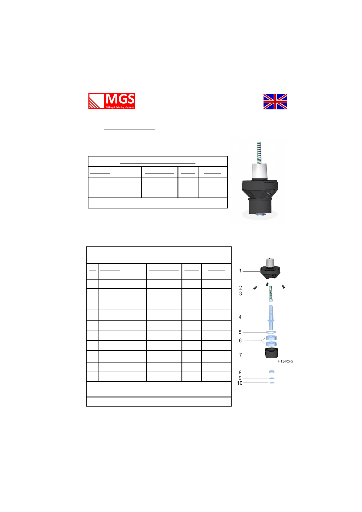
17c.
Standard milling tool
Milling head unit 45°-R3 -HBM 15*
Po . De cription Short de cription Number Order No.
1 Milling head 45°-HBM 15 F15-45°-2 1 0101.313-102
2* Plate clamping crew PKS-4x11 3 0101.113-4
3 Locking crew M6 x 40 –12.9 1 0101.313-108
4 Milling axi FA 15 1 0101.113-2
5* Locking ring 471 30 x 1 1 0101.313-112
6 Bearing 6200 2ZR Ø 30,0 2 0101.313-71
7 Sleeve H15-R3-5 1 0101.313-116
8 Di tance H15-45 10x16x4 1 0101.313-113
9* Shim ring 10x16x0,2 1 0101.313-115
10* Locking ring 471 10x1 1 0101.313-111
* The po ition 2,5,9 and 10 are delivered in packaging unit of 10 piece .
Milling head unit are alway delivered without indexable in ert .
Li ted part available eparately a pare part
Milling head unit completely mounted
De cription Short de cription Number Order No.
Milling head unit
45°-R3-HBM 15
FE-15-45°-R3 1 0101.113-6
*Milling head unit are alway delivered without indexable in ert .
Standard milling tool

20
24.11.14 / V 01.0-EN
17d.
Standard milling tool
Milling head unit 45°-R4 -HBM 15*
Standard milling tool
Po . De cription Short de cription Number Order No.
1 Milling head 45°-HBM
15
F15-45°-2 1 0101.313-102
2* Plate clamping crew PKS-4x11 3 0101.113-4
3 Locking crew M6 x 40 –12.9 1 0101.313-108
4 Milling axi FA 15 1 0101.113-2
5* Locking ring 471 30 x 1 1 0101.313-112
6 Bearing 6200 2ZR Ø 30,0 2 0101.313-71
7 Sleeve H15-R4-6 1 0101.313-117
8 Di tance H15-45 10x16x4 1 0101.313-113
9* Shim ring 10x16x0,2 1 0101.313-115
10* Locking ring 471 10x1 1 0101.313-111
* The po ition 2,5,9 and 10 are delivered in packaging unit of 10 piece .
Milling head unit are alway delivered without indexable in ert .
Li ted part available eparately a pare part
Milling head unit completely mounted
De cription Short de cription Number Order No.
Milling head unit
45°-R4-HBM 15
FE-15-45°-R4 1 0101.113-7
*Milling head unit are alway delivered without indexable in ert .
Table of contents
Other MGS Power Tools manuals


