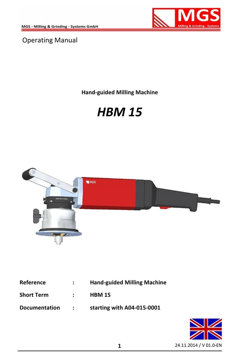
MGS HBM R3 User manual

24.11.2014 / V 01.0- E
1
Reference : Hand-guided Milling Machine
Short Term : HBM R3
Documentation : starting with A0 -003-0001
Operating Manual
Hand-guided Milling Machine
HBM R3

2
24.11.14 / V 01.0-E
Imprint
Company: MGS –Milling & Grinding –Systems GmbH
Adresse: Schwalbenweg 2
66620 Nonnweiler-Braunshausen
Phone: + 9-(0)6873 / 6690021
Fax.: + 9-(0)6873 / 6690020
Mail: info@mgs-maschinen.de
Mobile: + 9 -(0)160-77 2 3
Internet: www.mgs-maschinen.de
Managing Director: Guido Schnur
Entry in Commercial Register: HRB 101 269 Amtsgericht Saarbrücken
VAT Identification Number: DE 291 965 79
Relevant chamber: Arbeitskammer des Saarlandes

3
24.11.14 / V 01.0-E
Inhaltsverzeichnis
Subjet Page
Front page 1
Imprint 2
able of contents 3
Machine identification number 4
General safety information 5
Specific safety instructions 6
General Information 7
Components and intended use 8
echnical data 9
Operating 10
Vibration measurement 13
On- ime 14
Setting and adjustment of bevel size 15
Standard milling machine 16
Indexable cutting inserts for bevels 19
Indexable cutting inserts for radius 20
Setting and adjustment of radius 21
Operating of the machine 25
Schedule of maintenance 27
Service 28
Parts list - gear 32
Parts list - motor 34
Warranty conditions 37
EC Declaration of conformity 38

24.11.14 / V 01.0-E
Machine Identification
Number
Dear customer,
You have decided in favor of a high-quality hand guided bevel milling machine
of type HBM R3, which will enable you to easily and rapidly do your beveling
work of a real high quality. o ensure that the machine is used safely and pro-
fessionally we recommend you and your colleagues to thoroughly read these
operating instructions and to make the user acquainted with the machine.
A careful handling of the machine will prevent accidents, reduce costs and im-
prove the quality of your work piece.
Before being packed and delivered to you, the machine has been closely tested
and checked. In order to be able to help you as fast and efficient as possible
we would ask you to kindly indicate the MGS machine identification number
in any case.
his number is to be found in the supplied operating manual and engraved on
the gearbox flange of the machine.
Machine identification No. : _______________________________
(registered)
Gearbox flange
(engraved)
We thank you for using our machines and wish you always the best results
when working with our machines.
Your MGS – eam

5
24.11.14 / V 01.0-E
General safety Information
5. General Safety Information
Before using the machine, the operating manual and the safety information have to be
read in full and all instructions contained therein have to be followed. Safety instruc-
tions such as DIN, VDE, CEE, AFNOR and further instructions valid in the country of use
have to be strictly observed.
hese instructions cover the operating and handling of the machine including tools and
accessories as well as machine maintenance.
Disregarding these established safety recommendations may cause serious hazards. It
must be garanteed that the machine operator has clearly understood the following
recommendations and that he has access to them at any time.
he steps given below must be taken by the operator in any case to avoid improper
handling of the machine or to prevent accidents.
Installation
• he machine must only be connected to the voltage indicated on the machine's
label.
Danger to life from electrocution
• Before starting maintenance work disconnect the machine from the power
plug. he machine has to be unplugged and volt-free.
• Before each use check plug, cable and machine for signs of damage.
• he machine must be kept dry and not used in damp locations or humid envi-
ronments.
• If used outdoor, the machine must be protected by a residual-current circuit
breaker with a maximum tripping current of 30.
• Insert plug only when machine is switched off. Disconnect machine from power
plug after use.
Mandatory working clothes
• Always wear safety goggles, ear protection, protective gloves and safety shoes
when working with the machine.
• Wear tight-fitting clothes.

6
24.11.14 / V 01.0-E
Safety Information
6. Specific Safety Instructions:
Improper use can cause serious injury
• Don't reach with your hand into working area.
• Always hold the machine with two hands.
• Make sure you always have a safe position when working with the machine.
• Never touch the milling head when the machine is running.
• Do not use the machine for overhead work.
• he machine should only be used for up-cut milling.
Risk of injury from metal chips
• Hot chips are ejected from the machine at high speed.
• Use impact protection.
Risk of injury from ejected indexable inserts
• Use only original MGS inserts and clamping screws.
• ighten the clamp screws with 3 – 4 Nm torque.
Health risk in case of inhaling cutting oil
• Sufficient venting is essential for working with cutting oil.
• Do not inhale arising vapors.
Improper use can damage equipment and property
• Risk of machine being damaged or destroyed.
• Do not lift or carry the machine by its power cable.
• Make sure the cable is directed behind and away from the machine.
Do not pull the cable over sharp edges.
• Servicing and testing must be done by qualified personnel only.
• Always use original MGS spare parts and accessories.

7
24.11.14 / V 01.0-E
Grundsätzliches
7. General Handling
a. Security
b. Working Direction
Using our hand guided milling machines, always work
against the direction of rotation of the milling head
('up-cut milling').
his means to observe the working direction from
left to right in case of plate working starting in front
at the top
and clockwise in case of working on bore holes or
channels.
c. Bore Diameter or Inner Radius
In order to avoid a hooking of the cutting plates on
starting the beveling of bore holes, the bore hole
should always be at least 1.5 fold of the guide
bearing.
In case of guide bearing of 45° milling machine the
bore diameter is thus 24,8 mm x 1.5 = 37,2 mm.
Considering sufficient inner radius for beveling of
inner radius is also very important for safe working!
For all maintenance work the
machine must be disconnected from the
power supply system!

8
24.11.14 / V 01.0-E
Functional parts
Intended use
8. Description of machine
1 rear handle
2 motor
3 front handle
4 vernier scale
5 guide
6 speed control
7 on switch with lock-out feature
8 Milling head with cutting inserts
9 Guide bearing
10 set ring for height
adjustment
11 height clamping
12 height scale
13 locking button
Intended use:
he hand guided edge milling machine HBM R3 is an electrically powered
machine for the working of work pieces made of:
Steel, cast steel, fine-grained steel, stainless steel,
aluminium, aluminium alloys, brass and plastics
he machine is designed for industrial use in industry and small trade.
- for creating visible edges in plant, tool and mechanical engineering
- for edge rounding to prepare materials for optimal painting or
• coating or as bump protection.
1 2
5
4
3
6
8
9
11
7
12
13
10

9
24.11.14 / V 01.0-E
echnical Data
9. Technical Data:
Edge Milling Machine
HBM R3
supply voltage 110 / 230 V
frequency 50/60 Hz
input power 1200 W
idle speed 2000-6500 rpm
approximate weight 3.5 kg
bevel width (material dependent)
aluminium 1-4 mm
steel 1-4 mm
stainless steel 1-3 mm
minimum thickness of work piece 3 mm
smallest contour radius
at 45° 18,5 mm
smallest bore diameter
at 45° 37,2 mm
edge radius 3 mm
Subject to technical modifications and/or amendments by the manufacturer!

10
24.11.14 / V 01.0-E
Machine Operation
10. Changing the cutting tool
Overheated tools and milling head
Attention: burn hazard!
Always wear protective gloves when changing
the cutting tool.
Remove the clamping screw on the side of the
housing with the clamping, using the hexagon
wrench SW 3.
Remove the holder, complete with the
guiding plate, downwards.
o block the drive shaft, use the special wrench
SW 17, the hook wrench 45-50
is used for loosening the milling head.
For all maintenance work the
machine must be disconnected from the
power supply system!

11
24.11.14 / V 01.0-E
Machine Operation
Changing the cutting tool
Do not use the lock button for changing the
milling head.
Put the machine on a solid base and set the
hook wrench. Remove the milling head
counter clock wise
and unscrew it from the spindle.
In reverse sequence, a new milling head can be mounted.

12
24.11.14 / V 01.0-E
Indexable inserts
11. Changing the indexable cutting inserts
Property damage caused by blunt tools
Overcharge of the machine!
Regular testing of tools for abrasion is
recommended.
Please wear protection gloves when changing
the indexable cutting inserts.
In order to change the cutting inserts which can be
used with the edge milling machine HBM R3, kindly
proceed as follows:
Place the machine on the upper surface and turn the
guiding plate downwards as much as necessary to
get the cutting inserts totally free so that you can
turn them easily or exchange them.
Always use a orx 15.
We recommend to change defective plates or insert
screws immediately.
o avoid a turning away of the milling tool, lock
the drive shaft with the lock button.
For all maintenance work the
machine must be disconnected from the
power supply system!
The carbide inserts must always be mounted in the same drill
hole line.
Mounting the carbide inserts offset will result in imbalance an
can lead to serious damages.

13
24.11.14 / V 01.0-E
Noise Emission
Vibrations
Noise emission Value
Emission-noise level (LPA typically dB (A) 85
Emission-noise level (LWA typically dB (A) 98
uncertainty K for Emission-noise level aB 3
Noise emissions value according to
DIN EN 607 5-1
Vibration:
Wear hearing protection!
Note: he measurements were performed on a technically comparable machine
.
Total value of vibration
(Vector sum of three directions)
Unit Value
DIN 6075
Vibration emission value ah m/s² 4
uncertainty K for vibration emission value m/s² 1,5
Advice:
he above mentioned measured values depend on material and application
and can therefore be exceeded.
In case bevels wider than admissible are worked, the values of vibration and
noise are increasing to the same extent.

1
24.11.14 / V 01.0-E
On-time
We fitted our milling machines with an optimal bearing and a very good lubrication
system. This complex construction which was designed for these extreme applica-
tions, does not prevent damages if the machine is improperly used. To avoid such
damages the indicated on-time should always be respected.
In addition to the high evolution of heat of the electric motors at the stay and at the
magnetic field there is also more high temperature on milling.
his heat is largely dissipated by the metal chips. In case of longer lasting, continuous
operation the milling head can get hot on operation which on its turn transmits the
heat over the drive shaft to the cabinet and thus also on the driving motor.
A great deal of this heat is dissipated by the ventilators of the electric motors. However,
in case of long lasting operation, especially on high load due to broad bevels, hard ma-
terial or blunt cutting inserts, this cooling is no longer sufficient and there is the risk
that the isolation of the armature winding is damaged which might lead to short-circuit.
hus take care that the bevel adjustment is not too high. In case of large bevels it is
better to work a bevel in several strokes. his also involves that there is less vibration
leading to less stress on the person working with the machine, the machine itself and
the cutting inserts. Blunt inserts increase vibration. herefore care for a timely change
of the cutting inserts. his preventive measure also conserves your machine.
If the motor is getting too hot it is automatically switched off. Let the motor and the
cabinet cool down so that you can continue your work.
Number of strokes
When milling in several strokes there is less vibration and the cutting inserts are
conserved.
bevel width
bis 4mm idle speed Power-on time
Aluminum, copper,
b
rass, plastics
1 5 60-80%
Steel bis 400N/mm² 1 5 40-60%
Steel bis 600N/mm² 1 5 30-50%
Stainless steel 1-2 4-5 20-40%

15
24.11.14 / V 01.0-E
Machine adjustments
11
12. Machine adjustments
he bevelling size is by determined by the
height adjustment of the guide bell and
through the milling head angle
he divisions of the scale are indicative;
the height adjustment of vernier vernier
arrow next arrow are 0.05mm. hus, you
can adjust very precisely the amount
For this, open the clamp and rotate the guide bell to the desired scale
level. hen close the clamp and the height adjustment is complete.
On the left side of the HBM R3 you see a
smaller and a larger circle. hey symbolize
the different distance guiding bearings.
he “marking” smaller circle is used for
the distance guiding bearing
( H3-R3-3) Ø 24,8 mm.
For using the distance guiding
bearing Ø 32,8mm (H3-R3-4), position the
rim of the guiding bell to the adjusting
height with the marking larger circle.
After adjusting customize a sample piece and check the dimensions.
Due to manufacturing tolerances, a readjustment may be necessary
11

16
24.11.14 / V 01.0-E
Adjusting the bevel height
12. Machine adjustments
On the right side, you can
see the adjusting scale for the
bevel dimension / bevel width.
he Bevel width can be adjusted
by turning the guiding bell.
.
After adjusting customize a sample piece and check the dimensions.
Due to manufacturing tolerances, a readjustment may be necessary.
bevel width at angle
bevel height
45°
1 1,4
2 2,8
3 4,2
all specifications in mm

17
24.11.14 / V 01.0-E
13. Standard-milling tool
Milling head unit 45°-HBM R3
listed parts available separately as spare parts
Pos. Description Short description Number Order No.
1 Milling head 45°-HBMR3 F3 -45°-7 1 0101.313-107
2* Plates clamping screw PKS-4x11 3 0101.113-4
3 Distance H-R3 6-9x4,2 1 0101.313-138
4* Locking ring 472 19x1 1 0101.313-139
5 Bearing 626 2ZR Ø 19,0 2 0101.313-140
6 Sleeve H R3 R3.2—Ø32,8 1 0101.313-142
7 Fitting bolt M5 –6x20 1 0101.313-143
8* Locking ring 472 19x1 1 0101.313-139
9 Bearing 626 2ZR Ø 19,0 2 0101.313-140
10 Sleeve H R3 R3.1—Ø24,8 1 0101.313-141
11 Fitting bolt M5 –6x20 1 0101.313-143
* he positions 2,4 and 8 are in packaging unit of 10 pieces
delivered.
Milling head units are always delivered without indexable inserts.
Standard milling tool
Milling head unit completely mounted
Description Short description Number Order No.
Milling head unit
45°-R3-HBM R3
FE-3-45°-R3 1 0101.113-16
*Milling head units are always delivered without indexable inserts.

18
24.11.14 / V 01.0-E
14. Standard-guide sleeve
Guide—sleeve R3.1
Guide—sleeve R3.2
Guide-sleeve unit completely mounted
Description Short description Number Order No.
Guide-sleeve R3.1—Ø 24,8mm 1 0101.313-147
Standard-milling head
Guide-sleeve unit completely mounted
Description Short description Number Order No.
Guide-sleeve R3.2—Ø 32,8mm 1 0101.313-148

19
24.11.14 / V 01.0-E
15. Consumables
On the HBM R3 following inserts are used :
For milling of bevels = WP
Depending on the material to be processed, we offer you
following coatings for indexable inserts
Other coatings on request
Description Coating Colour
Short description
Order-No.
WP -X0 Uncoated Light gray X-0 0101.213-17
WP -X1 ExTin Gold X-1 0101.213-18
Material Coating Colour Description
Alu, copper, brass Uncoated Light gray X-0
Steel bis 00 N/mm² ExTin Gold X-1
Steel bis 600 N/mm² ExTin Gold X-1
Stainless steel ExTin Gold X-1
Cutting insert

20
24.11.14 / V 01.0-E
Cutting insert
16. Consumables
On the HBM R3 following inserts are used :
For milling of radius = WP -6R3
Radius 3mm WP -6R3
Other coatings on request
Description Coating Colour
Short descripti-
Order-No.
WP -6R3-X0 Uncoated Light gray X-0 0101.213-19
WP -6R3-X1 ExTin Gold X-1 0101.213-20
Table of contents
Other MGS Power Tools manuals
