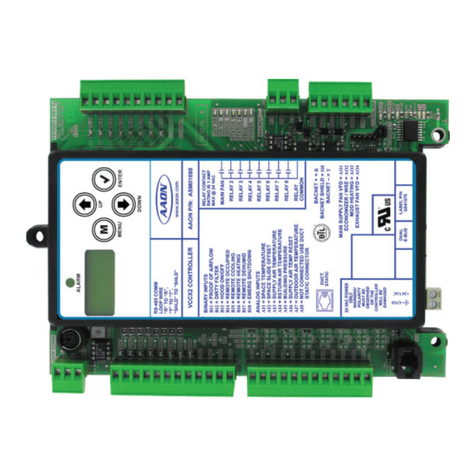
MH Corbin CONNECT:ITS Series Guide

MH Corbin CONNECT:ITS
User Installation Manual
Version 3.3
September 12, 2019
MH Corbin
6077 Frantz Rd Suite 203
Dublin, OH 43017
800-380-1718
http://mhcorbin.com

2
Table of Contents
Overview.......................................................................................................................................................4
Installation ....................................................................................................................................................5
Mounting.......................................................................................................................................5
Connect:ITS 19 ......................................................................................................................................5
Connect:ITS DIN ....................................................................................................................................5
Power Hook Up..............................................................................................................................5
Connect:ITS 19 ......................................................................................................................................5
Connect:ITS DIN ....................................................................................................................................5
Indicators and Connectors..............................................................................................................5
Connect:ITS 19 ......................................................................................................................................5
Connect:ITS DIN ....................................................................................................................................7
Administration ............................................................................................................................................11
Connecting to the Connect:ITS......................................................................................................11
Control Page ................................................................................................................................12
Setup Page...................................................................................................................................13
Disabling Items on Display Screen: IP Address ...................................................................................13
Disabling Backlight, and Heartbeat light.............................................................................................13
Location...............................................................................................................................................14
Ping Remote Host: ..............................................................................................................................14
Setup / IP page.............................................................................................................................14
Dual NICs and Bridged Mode..............................................................................................................15
DHCP ...................................................................................................................................................16
Static IP................................................................................................................................................16
Setup / Password Page.................................................................................................................17
Setup / Scripts..............................................................................................................................17
Setup / ITS Sensor ........................................................................................................................17
Setup / Modem Page....................................................................................................................18
PPP peer port Step 1........................................................................................................................18
Modem Provisioning Step 2................................................................................................................18
PPP Chat Script Step 3.........................................................................................................................19
PPPo Adapters Step 4..........................................................................................................................19
Perform Manual PPP Connection Step 5 ............................................................................................19

3
Show Addresses and Routing Step 6...................................................................................................19
Change Default Route Step 7..............................................................................................................19
Command Execution...........................................................................................................................19
Change log...................................................................................................................................................20

4
Overview
The Connect: ITS is a controller that provides connectivity and data collection services for various
ITS/weather sensors. The Connect communicates via TCP/IP over NTCIP, HTTP, and Representational
State Transfer (REST) protocols. The Connect includes a built-in web-based configuration and
management GUI as well as support for running multiple user created Python scripts that can be used
for automation of device control or data logging.
The Connect is available in two form factors.
The Connect:ITS 19 supports a built in Verizon Skywire modem that can provide cellular connectivity and
GPS location as well as a 915MHz radio for the MH Corbin VX21 pavement sensor. Connect:ITS DIN
supports the Connect:ITS 19 options and supports an Iridium satellite communications module.
The low power requirements of the Connect makes it a viable option for solar powered applications.
Connect: ITS currently integrates with the following sensor options:
Lufft WS100 UMB
Precipitation Sensor
Lufft WS200 UMB
Wind Sensor
Lufft WS300 UMB
Compact All in One Atmospheric Sensor
Lufft WS400 UMB
Compact All in One Atmospheric Sensor
Lufft WS600 UMB
All in One Atmospheric Sensor
Lufft NIRS31 UMB
Non-invasive Pavement Sensor
Lufft VS2K UMB
Visibility Sensor
Lufft R2S UMB
Precipitation Sensor
MH Corbin VXMS Radio
VX-21 Monitor Radio
Vaisala DSC111
Non-invasive Pavement Sensor
Vaisala PWD12
Visibility Sensor
ISS SX300
Radar Traffic Sensor (statistical)
Wavetronix HD
Radar Traffic Sensor (per vehicle)
Bosch
Video Sensor
Cepton
Lidar Sensor
The Connect can also be configured for additional sensors if they support one of the following
communication types:
RS/485
USB
RS/232
Ethernet
5VDC GPIO
19” Rack-Mounted Unit (referred to as
Connect:ITS 19 in this document):
Din-Rail Mounted Unit (referred to as
Connect:ITS DIN in this document):

Installation
Mounting
Connect:ITS 19
Connect:ITS 19 comes configured for a 19 “rack mount cabinet installation. The Connect:ITS 19
enclosure is 10.5” D X 3.5”H X 19” W, and it weights approximately 10lbs. Four rack mount screws can
secure the enclosure into the rack through four mounting holes located on the front panel.
Connect:ITS DIN
Connect:ITS DIN comes configured for din-rail and shelf mounting. The Connect:ITS DIN enclosure 3” D x
5” H x 6” W, and it weighs approximately 1.5lbs. It is recommended to install by placing the top mount
point of the Connect:ITS DIN with the spring on the top of the rail first. While pressing the top of the
Connect:ITS DIN down swing the bottom part of the mount inwards toward the rail.
Power Hook Up
Connect:ITS 19
Power is supplied through a 12VDC 2.5-amp power supply, or from a 12VDC battery. Power is provided
to the power connector located on the back of the Connect:ITS 19 enclosure.
Connect:ITS DIN
Power is supplied through a 12VDC or 24VDC power supply, or from a 12VDC or 24VDC battery. Power
is provided via a 2-pin Phoenix connector on the bottom of the Connect:ITS DIN.
Indicators and Connectors
Connect:ITS 19
Front Panel LEDs
PWR
Lights green when the unit is receiving power from the
backplane.
SBC
Lights green when the internal Computer has powered
up.
HDD
Flashes green during disk activity
HBT
Flashes green when unit is operating normally.

6
Front Panel Connectors
Rear Panel Connectors
RS485 #1, 2
Sensor Input connector for sensors that utilize the RS485 serial data
connections.
RS232 #1, 2
Connector for RS232 sensors.
USB #1, 2
Connector for USB sensors.
Cell
Antenna connector for internal cellular modem.
GPS
Antenna connector for internal cellular GPS.
VX
Antenna connector for 915Mhz internal radio.
Display Button
This button allows user to cycle through pertinent system information
such as: IP address, IP Mode, CPU Temp (C), Firmware Version
GPIO
10 General Purpose pins used for analog/digital inputs and outputs.
Power Jack
12VDC Power Input (12VDC 2.5-amp) size 2.1mm X 5.5mm.
Fuse Holder
2.5-amp Slow Blow fuse.

7
Connect:ITS DIN
Front Panel
Display Button Modes
Figure 1, IP First IP Address for Eth #1
Figure 2, IP Address Type shown as Static.
Can be changed to DHCP in Setup.
Figure 3, CPU Temperature shown as Celsius.
Can be changed to Fahrenheit in Setup.
Figure 4, Firmware Version
Front Panel LEDs
LCD
Screen
Displays unit information IP
address, IP Mode, CPU Temp
(C), Firmware Version
Display
Button
This button allows user to cycle
through pertinent system
information such as: IP
address, IP Mode, CPU Temp
(C), Firmware Version.
ON/OFF
This button turns the
Connect:ITS DIN on and off
HDD
Flashes orange during disk activity
SBC
Lights green when the internal Computer has powered
up.
PWR
Lights green when the unit is receiving power from the
backplane.
HBT
Flashes blue when unit is operating normally.

8
Bottom Panel Connectors
Antenna Connectors
Cell
Antenna connector for internal cellular modem.
Div
Antenna connector for internal cellular modem.
GPS
Antenna connector for internal cellular GPS.
SAT
Antenna connector for internal Iridium satellite communications
module.
VX
Antenna connector for 915Mhz internal radio.

9
Exploded View of RS485 / GPIO Pinout
RS232 Connectors
ttyXRO, ttyXR1,
ttyXR2 and ttyXR3
Sensor Input connector for sensors that utilize the RS485 serial
data connections
AI1 and AI2
Analog inputs 0,5 volts
DO1 and DO2
Digital Outputs 0,5 volts
5V
Regulated 5VDC for powering external devices or sensors. Input
voltage must be 13.8VDC or greater. Max of 1A output.
12V
Regulated 12VDC for powering external devices or
sensors. Input voltage must be 13.8VDC or greater. Max of 1A
output.
VIN
Passthrough input voltage for powering external devices or
sensors. Max of 1A.
GND
Common ground with input voltage
ttyS0 and
ttyS1
Sensor Input connector for
sensors that utilize the RS232
serial data connections

10
USB Connectors
Power Connector
Ethernet Ports
Display and Audio Connectors
USB connectors for sensors that utilize USB
data connections
Two pin Phoenix style power connector.
Supports 12-24 VDC
Dual ethernet ports with bridging capability
**reserved for future use**

11
Default passwords
are:
Login:
username: control
password: control
Setup:
username: setup
password: setup
Administration
Connecting to the Connect:ITS
After booting up, the Connect: ITS will display its current IP address on the LCD screen. You can then use
a laptop/web browser to connect to the unit’s web interface as follows:
Connect your laptop to the Connect: ITS Ethernet port
(on the blue faceplate) using an Ethernet patch cable.
Ensure that the laptop is set to use a static IP which is
in the same Subnet as the Connect: ITS’s current IP
address (obtained from front panel LCD display, Figure
1).
Open a web browser and navigate to the Connect: ITS URL using the following format:
If successful, you will be presented with the Connect: ITS login page. Click on the Login link:
Enter the username and password, by default these are factory set to
control, control
Figure 5, First IP Address on LCD Screen for Eth #1 Port
http(s)://{ipaddress}

12
After a successful login, the main page is displayed, and various features can be accessed via a two-tier
menu system. The top-level menu has two tabs, labeled CONTROL and SETUP:
The 2nd tier menu allows access to the features selected on the top tier menu. In the above example,
the CONTROL tab is selected which includes the WEATHER and V2I feature pages.
Control Page
The default Control page shows the system status:
The digital outputs of the Connect:ITS can be toggled on or off using the buttons in the right column.
NOTE:
Both the
CONTROL
and
SETUP
tabs
are protected, and each has its own
username and password.

13
Setup Page
Setup page allows users to enter configuration information for Connect: ITS.
-Click on the Setup toolbar button:
-Enter the “setup” username and password, by default these are factory set to setup, setup
Disabling Items on Display Screen: IP Address
By default your box will have the IP address enabled. To turn off the Display’s IP address scroll down the
Setup page to the “Configure LCD screen” section. Uncheck “Enable IP address display” and click submit.
It is important to then press the “Display” button and cycle the screen. Otherwise the IP Address will
continue to display.
Disabling Backlight, and Heartbeat light
By default your box will have the backlight and the heartbeat led lit or flashing respectively. To disable
them scroll down the Setup page to the “Configure LCD screen” section. Uncheck “Enable backlight” and
click submit. The backlight and the heartbeat will instantly cease to function until re-enabled.

14
Location
Enter location description, or name to identify this Connect: ITS unit, latitude, longitude and altitude
information.
Ping Remote Host:
By entering a valid IP address of a host machine you can ensure that a connection between that host
and the Connect:ITS is able to ping properly.
Setup / IP page
The Connect: ITS supports two IPv4 network ports through DHCP and Static addressing. From the
factory, the unit comes with a static IP configured.

15
Dual NICs and Bridged Mode
Only the primary NIC interface settings will be shown by default. To show settings for the 2nd NIC, check
the Enable dual NIC mode and press the SUBMIT button. It may take up to a minute to refresh the
page, which will then show the 2nd NIC adapter settings box:
If using the 2nd NIC adapter, it can be bridged with the primary NIC to allow pass-through IP for a 2nd
device, such as an IP camera. This would allow up to two IP devices to be connected to a modem
without the need for an additional switch.

16
DHCP
To allow a host system to assign an IP address automatically select the Assign automatically with DHCP
radio button.
Static IP
To assign a static IP address to Connect: ITS fill in the IP, Network mask, Broadcast, and Gateway fields
with valid IP information.
-Choose DHCP or static addressing and click Submit
-Wait a few minutes until the address change completes
-Enter the new IP range into the laptop if necessary (network adapter settings on laptop or
computer)
-Restart the web browser with the new IP address
NOTE:
Important information
about the Connect: ITS system is
located at the bottom of each
page such as: MAC Address,
Firmware Version, Refresh Date
Stamp

17
Default passwords
are:
Login:
username: control
password: control
Setup:
username: setup
password: setup
Setup / Password Page
Use this form if you want to change the default passwords for the Control and Setup page. MHC
recommends that you change the passwords since the default passwords are published.
Setup / Scripts
Scripts are an advanced feature of the Connect:ITS and require software development skills and a
programming background. Example scripts can be found in the Connect:ITS Software Interface User
Manual.
Setup / ITS Sensor
If a sensor is supported by the Connect:ITS you can find the appropriate manual in the resource section
of the MH Corbin website.

18
Setup / Modem Page
An internal modem is integrated into the Connect: ITS system which can provide the Connect: ITS with
data access without the need to purchase an additional equipment. The modem is setup for operation
by clicking on the Modem tab:
PPP peer port Step 1
NOTE: You only need to change this setting if the modem port has changed since factory setup. To setup
just select the serial port the modem is using.
Modem Provisioning Step 2
Select the modem type supplied with the Connect: ITS and click the Submit button. The modem will be
provisioned OTASP (Over The Air). NOTE: The modem needs to have IMEI and be activated by Verizon.
This step only needs to be completed if the modem has not been provisioned before or if the modem has
been replaced. A data plan associated with the SIM card IMEI needs to setup prior to completing this
step.

19
PPP Chat Script Step 3
Use the same selection here as was used in step #1.
PPPo Adapters Step 4
This sets the network adapter for the modem.
Perform Manual PPP Connection Step 5
This connects or disconnects the Modem through PPP to the cellular network.
Show Addresses and Routing Step 6
If you select Show it will show all the IP addresses that are assigned to the modem.
Change Default Route Step 7
Select either modem or Ethernet as the default route for devices connected to the Ethernet through the
Connect: ITS external Ethernet ports.
Command Execution
This field allows users to execute a Linux command on the Connect: ITS system. For example, if you type
in ls -l you get a listing of everything in the root directory. This is for troubleshooting purposes and only
use this when directed by MH Corbin Personal.

20
Change log
Version/Author
Comments
Date Published
Version 1.0
Mike Menter
Published Version 1.0
9/19/17
Version 2.0
Mike Menter
Updated User Manual to 2.0
8/10/2018
Version 3.0
Brandon Whitaker
Updated User Manual to 3.0
6/5/2019
Version 3.3
Robert Mathis
Updated User Manual to 3.3
Revised information contained
Updated branding
Updated/Changed content
9/6/2019
Version 3.3
Brandon Whitaker
Robert Mathis
Updated/Changed content
9/9/2019
Version 3.3
Robert Mathis
Added sensor, changed company address
10/2/2019
This manual suits for next models
2
Table of contents
