manuals.online logo
Brands
  1. Home
  2. •
  3. Brands
  4. •
  5. Linear Technology
  6. •
  7. Controllers
  8. •
  9. Linear Technology LTC2920-1CS5 User manual

Linear Technology LTC2920-1CS5 User manual

QUICK START GUIDE FOR DEMONSTRATION CIRCUIT 563
SINGLE AND DUAL MARGINING CONTROLLER
1
LTC2920-1CS5
LTC2920-2CMS8
DESCRIPTION
Demonstration circuit 563 contains two separate cir-
cuits: a (single channel) LTC2920-1 and a (dual chan-
nel) LTC2920-2 Power Supply Margining Controllers.
This board is meant to be connected to up to three
power supplies and demonstrates the voltage margin-
ing capabilities of the LTC2920. The board is scribed
for easy separation of the two circuits if desired.
Each circuit contains a Margining Controller, bypass
capacitor, and pads for external connections. There
are also component locations for adding 0805 resis-
tors. These resistors are specific to each applica-
tion and must be installed to demonstrate Voltage
Margining.
Design files for this circuit board are available. Call
the LTC factory.
QUICK START PROCEDURE
Referring to Figure 1, the Vcc1 and Gnd1 pins provide
the power and ground connections for the LTC2920-1
(single). The Vcc2 and Gnd2 pins provide the power
and ground connections for the LTC2920-2 (dual).
The Vcc voltage can generally be varied between 2.2V
and 6.0V. Vcc must be at least 0.6 volts higher than
the voltage at the Im pin. See the LTC2920 Data
Sheet for other design considerations on minimum
Vcc voltage and Vcc filtering. Be sure to connect the
ground pin(s) to the same ground as the power sup-
ply(s) being margined.
For margining power supplies with external feedback
resistors, the Im pins should be connected to the
power supply feedback node. For margining power
supplies using trim pins, the Im pin should be con-
nected to the power supply trim pin.
The Imargin current sourced or sunk from each Im
pin is individually programmed by its respective on
board Rset resistor. For the LTC2920-1 circuit, there
are two possible locations for the Rset resistor. Plac-
ing the Rset resistor in the ‘RLOW’ position will pro-
gram the Imargin current at 1V / Rset. Placing the
Rset resistor in the ‘RHI’ position will program the
Imargin current at 30 * 1V / Rset. See the LTC2920
Data Sheet for the specification limits of the high and
low current ranges. On the LTC2920-2 circuit, there
are two positions for each of the two Rset resistors.
The ‘R1L’ and ‘R2L’ positions are similar to the
‘RLOW’ position described above. The ‘R1H’ and
‘R2H’ positions are similar to the ‘RHI’ position de-
scribed above.
The In pins can be connected to a system controller
that has a 3-state output, or manually connected as
shown. When using a 3-state output to control the In
pin, placing the (3-state) output in the high-Z state
will ‘float’ the In pin, and cause the controlled Im pin
to be in a high impedance state. Raising an In pin
above 2.0 Volts will cause its respective Im pin to
sink current. Lowering an In pin below 0.6 Volts will
cause its respective Im pin to source current. See the
LTC2920 Data Sheet for details. The In pins may also
be controlled manually by connecting them to Vcc,
ground, or left floating.
After calculating and inserting the Rset resistor(s) as
described above, place the DC563 board as close as
possible to the power supplie(s) being margined. The
ground, Vcc, and Im pins should be connected with
the shortest practical wires.
With power applied, the power supply output(s)
should be at their nominal values with the In pin(s)
QUICK START GUIDE FOR DEMONSTRATION CIRCUIT 563
SINGLE AND DUAL MARGINING CONTROLLER
2
floating. Raising the In pin(s) above 2.0 V will cause
the power supply output voltage to increase by the
desired margin voltage. Lowering the In pin(s) below
0.6 V will cause the power supply output voltage to
decrease by the desired margin voltage. When con-
nected to ‘trim’ pins on DC to DC modules, the po-
larity of the voltage margining may be inverted.
If the LTC2920 Vcc pin is connected to power sup-
plies that are compensated to be only ‘marginally sta-
ble,’ oscillations may be observed. If oscillations are
observed while margining a power supply, connect
the Vcc pin to the power supply using an axial lead
resistor instead of a wire. See the LTC2920 Data
Sheet for calculating the value of this resistor.
Figure 1. Proper Measurement Equipment Setup
QUICK START GUIDE FOR DEMONSTRATION CIRCUIT 563
SINGLE AND DUAL MARGINING CONTROLLER
3

This manual suits for next models

1

Other Linear Technology Controllers manuals
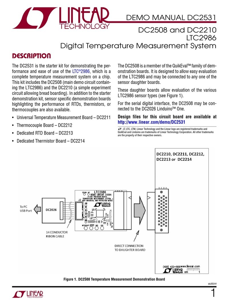
Linear Technology DC2543A Quick setup guide
Linear Technology

Linear Technology DC2543A Quick setup guide

Linear Technology DC1723A Quick setup guide
Linear Technology

Linear Technology DC1723A Quick setup guide

Linear Technology LTM 4601AHVEV User manual
Linear Technology

Linear Technology LTM 4601AHVEV User manual

Linear Technology LT3790 Quick setup guide
Linear Technology

Linear Technology LT3790 Quick setup guide

Linear Technology LTC3624 Quick setup guide
Linear Technology

Linear Technology LTC3624 Quick setup guide

Linear Technology LT8608 User manual

Linear Technology

Linear Technology LT8608 User manual
Linear Technology LTM4636 User manual

Linear Technology

Linear Technology LTM4636 User manual
Linear Technology DC1477B Quick setup guide
Linear Technology

Linear Technology DC1477B Quick setup guide

Linear Technology LTC1624 User manual

Linear Technology

Linear Technology LTC1624 User manual
Linear Technology LT3971 User manual

Linear Technology

Linear Technology LT3971 User manual
Linear Technology LTM4650EY-1 Quick setup guide
Linear Technology

Linear Technology LTM4650EY-1 Quick setup guide

Linear Technology LTC3703-5 User manual
Linear Technology

Linear Technology LTC3703-5 User manual

Linear Technology DC1830B-C Quick setup guide
Linear Technology

Linear Technology DC1830B-C Quick setup guide

Linear Technology LTC3880EUJ Quick setup guide

Linear Technology

Linear Technology LTC3880EUJ Quick setup guide

Linear Technology LT8611 User manual

Linear Technology

Linear Technology LT8611 User manual
Linear Technology DC2268A-1 Quick setup guide
Linear Technology

Linear Technology DC2268A-1 Quick setup guide

Linear Technology LT3507 Quick setup guide
Linear Technology

Linear Technology LT3507 Quick setup guide

Linear Technology LTM4649EY Quick setup guide
Linear Technology

Linear Technology LTM4649EY Quick setup guide

Linear Technology LTM4613 Quick setup guide
Linear Technology

Linear Technology LTM4613 Quick setup guide

Linear Technology LINEARCOM3000 LC3.IRTX User manual

Linear Technology

Linear Technology LINEARCOM3000 LC3.IRTX User manual

Linear Technology DC1084A-B User manual

Linear Technology

Linear Technology DC1084A-B User manual

Linear Technology LTC3542 User manual

Linear Technology

Linear Technology LTC3542 User manual

Linear Technology LTM4616 Quick setup guide

Linear Technology

Linear Technology LTM4616 Quick setup guide

Linear Technology DC1900A Quick setup guide

Linear Technology

Linear Technology DC1900A Quick setup guide

Popular Controllers manuals by other brands
Newport XPS Series Technical note

Newport

Newport XPS Series Technical note

American DJ FLASH 2C User instruction

American DJ

American DJ FLASH 2C User instruction

Q5X QT-256 user guide

Q5X

Q5X QT-256 user guide

Norac UC4+ NITRO Miller 3200 Series installation manual

Norac

Norac UC4+ NITRO Miller 3200 Series installation manual

Beck IPC SC123 Hardware manual

Beck

Beck IPC SC123 Hardware manual

Controls MVP-A12303 product manual

Controls

Controls MVP-A12303 product manual

Siemens SIRIUS 3RT203 S Series Original operating instructions
Siemens

Siemens SIRIUS 3RT203 S Series Original operating instructions

Star Progetti STAR 5 operating instructions

Star Progetti

Star Progetti STAR 5 operating instructions

Agilent Technologies 969-9871 instruction manual

Agilent Technologies

Agilent Technologies 969-9871 instruction manual

Comunello Automation SHOWIN S45 3FC instruction manual
Comunello Automation

Comunello Automation SHOWIN S45 3FC instruction manual

Mitsubishi FX0S Series quick start guide

Mitsubishi

Mitsubishi FX0S Series quick start guide

Planar AX3 quick reference

Planar

Planar AX3 quick reference
Balluff BIS00W2 installation guide

Balluff

Balluff BIS00W2 installation guide

Simrad OP10 installation guide

Simrad

Simrad OP10 installation guide

Peak Sensors VERTEX F4 instruction manual

Peak Sensors

Peak Sensors VERTEX F4 instruction manual

S&C 6800 Series instruction sheet

S&C

S&C 6800 Series instruction sheet

Digilent DMC60C Reference manual

Digilent

Digilent DMC60C Reference manual

Samson Type 5824 Mounting and operating instructions

Samson

Samson Type 5824 Mounting and operating instructions

manuals.online logo
manuals.online logoBrands
  • About & Mission
  • Contact us
  • Privacy Policy
  • Terms and Conditions

Copyright 2025 Manuals.Online. All Rights Reserved.