manuals.online logo
Brands
  1. Home
  2. •
  3. Brands
  4. •
  5. Carlin
  6. •
  7. Controllers
  8. •
  9. Carlin 51300AS Parts list manual

Carlin 51300AS Parts list manual

Installation Instructions
and Operating Manual
126 Bailey Road North Haven, CT 06473
Phone 203-680-9401 Fax 203-680-9403
Carlin Combustion Technology, Inc.
T
ech support
800-989-2275 carlincombustion.com
©Copyright 2018 – Carlin Combustion Technology, Inc.
CAP
System Kit
Combustion
Air Proving Kit with
Burner Cut-Off
Designed to meet NFPA31*
requirements for combustion air
CAP
Model Description Firing Rate (GPH) Contains
51300AS Low Rate CAP Kit
(for Carlin burners with covers) 0.50 - 1.00
1Air Pressure Switch Assembly with 50806A Switch, 2Combustion Air Inlet,
3Connecting Flange, 4Cover Seal Kit, 8Air Pressure Switch Wiring Harness,
93" Pipe Elbow w/ Birdscreen
51300BS Medium Rate CAP Kit
(for Carlin burners with covers) 1.05 - 1.45
1Air Pressure Switch Assembly with 50806B Switch, 2Combustion Air Inlet,
3Connecting Flange, 4Cover Seal Kit, 8Air Pressure Switch Wiring Harness,
93" Pipe Elbow w/ Birdscreen
51300CS High Rate CAP Kit
(for Carlin burners with covers) 1.50 - 2.00
1Air Pressure Switch Assembly with 50806C Switch, 2Combustion Air Inlet,
3Connecting Flange, 4Cover Seal Kit, 8Air Pressure Switch Wiring Harness,
93" Pipe Elbow w/ Birdscreen
51300S
Complete
CAP System Kit
(for Carlin burners without covers)
0.50 - 2.00
1
Air Pressure Switch Assembly with 50806A, B & C Switches,
2Combustion Air Inlet,
3Connecting Flange, 4Cover Seal Kit, 5Cover, 6Cover Back Plate,
8Air Pressure Switch Wiring Harness, 93" Pipe Elbow w/ Birdscreen
Note: All CAP System models require 7Carlin 70200 Primary Control manufactured after Sept. 2018
6 5
7
1
2
3
4Cover Seal Kit (not shown) – 50433KITS
8Air Pressure Switch Wiring Harness (not shown)
93" Pipe Elbow w/ Birdscreen (not shown) *See Section 5.4.3.3 as covered by April 2019 TIA 16-2
CAP System Operation
The CAP System is designed to shut down the burner in the
event the outside combustion air supply becomes blocked. At
each burner startup, the system will check the air intake during
pre-purge (Valve Delay On*). If the air is blocked, the control
will abort ignition and shutdown the burner. If the air intake is
not blocked during this startup test, but becomes blocked dur-
ing normal burner operation, the burner will shut down if the air
remains blocked for 20 seconds. Following any shutdown, the
burner will be permitted to recycle 3 times following a 1 minute
delay. The system will lock out the burner if the blockage con-
tinues throughout 3 recycles during any single call for heat.
**If the Burner has no valve, the air intake cannot be checked
during pre-purge. In this case, the burner will shut down
following the 20 second blockage described above. For all
burners with valves, Valve Delay settings of less than 15 Sec-
onds will be automatically changed to 15 Seconds to allow
for the prepurge test.
Getting Started
1Ensure you have the right CAP System Kit for your applica-
tion by confirming the firing rate (in GPH) with the table on
page 1.
IMPORTANT: If you change the firing rate, pressure switch-
es are available separately to convert the CAP System after
installation. (See instructions for Installing Pressure Switch
on page 4).
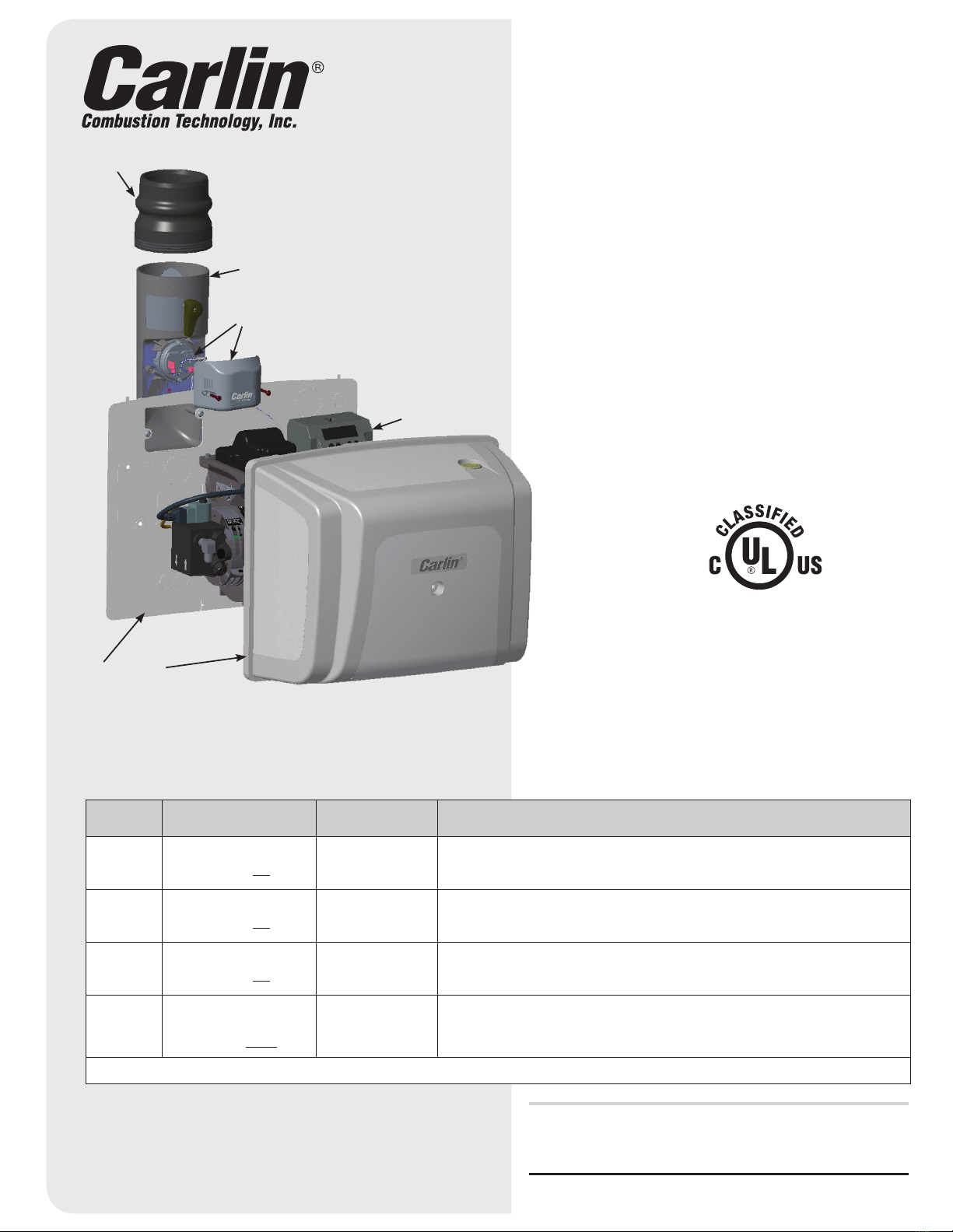
2Ensure that the burner is
equipped with a Carlin Pro-X
70200 primary control with
low voltage blocked
vent (BV) terminals as shown.
NOTE: 70200 controls
manufactured prior to
Sept. 2018 are not compatible
with the CAP System.
3INSTALLING BACK PLATE (for uncovered burners)
• Install the two mounting screws as shown
• Reroute the burner wire harness through the air inlet
knockout in the back plate
4ROUTE THE OIL
• The oil line must enter the burner cover through one of
the knockouts in the back plate.
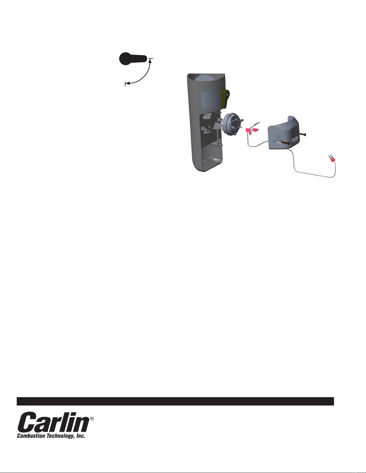
5REMOVE AIR INLET KNOCKOUT
• Remove the 2" x 4" air inlet knockout that corresponds
to the desired air inlet position (vertical or horizontal) as
shown in step 8.
6SEAL THE BACK PLATE
To prevent basement air from entering the cover, all holes
on the back plate must be sealed.
• Install the filler plate below the burner air tube using the
two 5/16" bolts provided. Use the plastic rivets at the
bottom corners of the filler plate to properly align the filler
plate with the burner back plate.
• Install the split grommet around the burner wire harness
• Install the split grommet around the oil line
• Fill the 1/4" and 7/8" holes in the back plate with plugs
provided
2
Pressure Switch Conversion
Firing Rate GPH Pressure Switch
0.50-1.00 50806A
1.05-1.45 50806B
1.50-1.90 50806C
7 SEAL THE COVER
• Install the rubber filler into the 4" opening in the bottom
of the cover as shown
8 INSTALL THE AIR INLET
• Using the screws provided, install the CAP System air
inlet onto the back plate
9 Slide the connecting flange onto the air inlet until
secure.
10 Route the wire leads from the air inlet kit to the low
voltage blocked vent (BV) contacts on the Pro-X 70200
primary control
11 SETTING BLOCKED VENT + AIR INTAKE FEATURE
The Pro-X 70200 Primary Control (manufactured
Sept. 2018 or later) is equipped with a Blocked Vent –
Air Intake feature. To activate this setting:
• Press and simultaneously for 2 seconds. This
brings you to the settings menu.
• Scroll through the different settings using until you
reach Vent Input.
• Scroll down to Intake using the .
• Press / ENTER button. The display will briefly indi-
cate Vent Input has been “Entered” and has replaced
any previous setting.
NOTE: If the Pro-X 70200 is also connected to a
blocked exhaust switch, call Carlin Technical Support
for assistance.
12 Install 3" PVC vent pipe to provide outside air to the
CAP System.
IMPORTANT:
For proper operation of the CAP System,
air inlet piping should only use schedule 40 or 80 PVC
pipe (maximum of 80' total with each elbow equal to 10').
Combustion air outdoor termination, use PVC elbow
(downward facing) and bird screen provided. Maintain
12" clearance above highest anticipated snow level.
Avoid locations where snow may drift and block com-
bustion air. Ice or snow may cause boiler to shut down
if combustion air becomes obstructed. Combustion air
termination must be min. 12" from or below doors, win-
dows or gravity inlet. USE SWEEP ELBOWS FOR ALL
COMBUSTION AIR PIPING. DO NOT USE short radius
elbows for combustion air piping – boiler performance
could be affected.
13 Mount the cover by aligning the two holes on the top
flange of the cover with the mounting tabs on the back
plate. Tighten the mounting screw, located in the center
of the cover, securely to prevent basement air from
entering the cover.
14 CHECK BURNER SETUP
Use the table below to set the combustion settings
based on outside temperatures at the time of setup.
CAP System utilizes outside air for combustion.
Incoming air temperature will fluctuate by season
which can significantly impact combustion.
Use below chart to ensure proper setup.
Incoming combustion
air temperature
during setup CO2min CO2max O2max O2min
–20°F to 0°F 10.2% 11.0% 7.0% 5.8%
5°F to 30°F 11.0% 11.5% 5.8% 5.5%
35°F to 60°F 11.5% 12.2% 5.5% 4.2%
65°F or higher 12.0% 12.5% 4.6% 3.9%
HORIZONTAL or VERTICAL
3
Testing CAP System Operation
1With the CAP System installed and the cover securely
mounted, initiate a call for heat and allow the burner to
fire.
2With the burner firing, move the
Test Lever to the TEST position
for 20 seconds. The burner will
shut down following the 20 second
delay.
NOTE: The 70200 will allow the
burner to recycle three times to prevent nuisance
shutdowns caused by temporary blockages or high wind
conditions. If the blockage persists the burner will shut
down and lock out after the third recycle attempt.
NOTE: If the burner does not have a prepurge cycle, the
burner will fire upon recycle, but will shut down following
20 seconds of operation. (See the 70200 instructions for
more details).
Annual Test
Using the instruction above, the CAP System operation should
be tested annually.
Troubleshooting
Burner Will Not Shut Down During Test
If the burner did not shut down with the test damper closed for
a sustained 20 seconds, check the following:
• Make sure that the burner cover is properly sealed. If a signif-
icant amount of air is leaking into the cover or back plate, the
burner will not shut down during the test. Check for proper
installation of all components in the Burner Seal Kit.
• Make sure that the burner cover screw is tight. This also
prevents basement air from entering the cover.
• Check that the correct air pressure switch is installed based
on the firing rate of the burner (See table on page 2 and
instructions for changing the switch on this page)
• Make sure Vent Input on 70200 control is set to “Intake” (see
step 11).
Changing the Air Pressure Switch
The air pressure switch must correspond with the firing rate
of the burner – see table on page 2. Carlin’s Complete CAP
System Kit (51300S) contains all three pressure switches.
Switches are also available separately. If you need to change
the switch to accommodate your application, follow the in-
structions below:
1Remove the switch cover which is secured by two mount-
ing screws (shown above).
2Unplug the two female fast-ons from the switch.
3Pull the switch outward to remove it from the assembly.
Replace it with the switch that corresponds to the burner’s
firing rate. Reattach the wires and secure the switch cover
TEST
RUN
MNCAP 071118
© Copyright 2018 — Carlin Combustion Technology, Inc.
TECH SUPPORT HOTLINE 800-989-2275
Carlin Combustion Technology, Inc.
126 Bailey Road North Haven, CT 06473 Phone 203–680–9401 Fax 203–764–1714
e-mail us at: [email protected] visit our website: www.carlincombustion.com
4

This manual suits for next models

3

Other Carlin Controllers manuals

Carlin SQN71 User manual

Carlin

Carlin SQN71 User manual

Carlin 60200FR User manual

Carlin

Carlin 60200FR User manual

Popular Controllers manuals by other brands

Emerson Fisher SR5 instruction manual

Emerson

Emerson Fisher SR5 instruction manual

Regin TTC40FX instructions

Regin

Regin TTC40FX instructions

Resol DeltaSol E manual

Resol

Resol DeltaSol E manual

Leroy-Somer R630 Installation and Maintenance

Leroy-Somer

Leroy-Somer R630 Installation and Maintenance

White Rodgers 50A62-820 user manual

White Rodgers

White Rodgers 50A62-820 user manual

Matsushita Electric NAiS FP Series Hardware manual

Matsushita Electric

Matsushita Electric NAiS FP Series Hardware manual

Zennio ZCL-8HT230 quick start guide

Zennio

Zennio ZCL-8HT230 quick start guide

Monicon GTR-680 user manual

Monicon

Monicon GTR-680 user manual

Moxa Technologies WAC-2004 Series Quick installation guide

Moxa Technologies

Moxa Technologies WAC-2004 Series Quick installation guide

Dorma USV-12V DC manual

Dorma

Dorma USV-12V DC manual

Titan Controls Helios 13 instruction manual

Titan Controls

Titan Controls Helios 13 instruction manual

Mitsubishi Electric MELSEC FX2N-16SW user guide

Mitsubishi Electric

Mitsubishi Electric MELSEC FX2N-16SW user guide

Grundfos LC A2 Installation and operating instructions

Grundfos

Grundfos LC A2 Installation and operating instructions

SIIG eSATA II PCIe Pro Quick installation guide

SIIG

SIIG eSATA II PCIe Pro Quick installation guide

JABSCO 31777-0000 INSTALLATION & SERVICE INFORMATION

JABSCO

JABSCO 31777-0000 INSTALLATION & SERVICE INFORMATION

Siemens instabus JB526C23 Technical manual

Siemens

Siemens instabus JB526C23 Technical manual

Eliwell ID 961 manual

Eliwell

Eliwell ID 961 manual

FlowLine LC11 Series owner's manual

FlowLine

FlowLine LC11 Series owner's manual

manuals.online logo
manuals.online logoBrands
  • About & Mission
  • Contact us
  • Privacy Policy
  • Terms and Conditions

Copyright 2025 Manuals.Online. All Rights Reserved.