MH Apollo-IV Guide
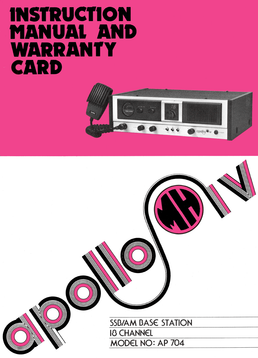
SSB/AM BASE STATION
18 CHANNEL
MODEL NO: AP 704
INSTRUCTION
MANUAL AND
WARRANTY
CARD

Introduction
Thank you for your confidence in se-
lecting
Ap9Ilo-IV
two-way radio. We know
you will find your transceiver as exciting
as it is practical. Only the highest quality
components are incorporated into
Apollo-
IV
to assure reliability and maximum
performance.
Installing and operating the
Apollo-IV
is not complicated, but the flexibility
provided by its many features may not
be fully appreciated until a little time is
spent becoming familier with its controls
and connections.
It will be to your adventages to save
all the packing materials — carton, fillers,
cushonings, etc., they will prove valuable
in preventing damage should you ever
have occasion to transport or ship the
Apollo-IV.
Licensing Information
Operation of this equipment requires
a valid station license issued by the
P and
T [Postal and Telecommunications De-
partment].
Do not
transmit with your
equipment until you have received your
license. Be certain that you have read the
P and T Form
RB 14
rules and regu-
lations before operating your station.
Licensing application is to be made on a
P and T Form
RB 13.
A copy of this
Form is furnished with your transceiver.
Installation
The transceiver should be placed in a
convenient operating location close to an
ac power outlet and the antenna lead-in
cable. To prevent fire or shock hazard,
do not expose this appliance to rain or
moisture.
Connections
The
Apollo-IV
is supplied with built-
in ac power cord and detachable dc power
cable.
Do not use both power supply
cable at the same time.
Proceed as follows
to complete all necessary connection to
the transceiver.
1.
Connect the antenna cable plug to
the standard receptacle on the rear
panel. Most CB antennas are termi-
minated with a type
PL-259
plug and
mate with the receptacle of your trans-
ceiver.
2.
AC Power Operation.
This trans-
ceiver has been designed primarily for
ac-power-supplied base station use.
Before inserting the ac plug into out-
let, make sure your transceiver is
off.
Insert the ac plug at the end of the
cable firmly into an ac outlet supply-
ing
240 volts, 50 or 60 Hz ac.
Also
make sure, when in ac operation, the
dc power cable plug is disconnected
from the transceiver. For protection,
the ac input circuit of the transceiver
is fused at the rear panel.
3.
DC Power Operation.
Your trans-
ceiver is capable of operation from a
dc power supply source of 13.8 volts
with low current drain, such as a
battery in the vehicle. This expedient
feature exhibits its convenience upon
such cases as, power failure, camping
site, on board, emergency or mobile.
First make sure the vehicle on which
you are going to install the transceiver
is
negative ground system. Do not
install the transceiver in a positive
ground type vehicle.
Failure to do so
may cause irrevocable damage to trans-
ceiver and your vehicle. Connect the
dc power cable plug to the dc
1
power socket
on rear panel of the
transceiver. The
red
lead at the power
cable connects to the
positive [+]
pole
of the battery or electrical system and
the
black
lead connects to the
negative [—]
pole of the battery or
suitable chassis ground.
4.
Mount the microphone hanger to
any convenient location close the
transceiver.
Noise Interference
There are several kind of noise inter-
fering you may encounter in base station
operation. Some of these noise sources
are, from nearby commercial broadcast,
electrical appliance, lawnmower etc., flo-
rescent buzz, static from electrical storms.
Commercial products are available to
reduce interference from these sources.
Consult with your dealer or CB/amateur
radio supply shop.
Antenna
Only a properly matched antenna
system will allow maximum power trans-
fer from the
52 ohms
transmission line
to the radiating element.
Note
that except
in special circumstances approved by
P and T
depertment, the use of parasitic
or driven elements to provide aerial gain
is not permitted. However, reactive load-
ing of aerials may be employed. A ver-
tically polarized quarter wave length
antenna provides the reliable operation
and greater range. We suggest vertical
ground plane antennas are omni-
directional that provide optimum per-
formance for contacting other fixed
stations using vertical type antennas in
additional to all mobile stations. For a
short range communications within build-
ings, from building to building, or
mobile [dc] operation, a short center-
loaded whip antenna is available for use
with your transceiver. A standard antenna
connector is provided on the transceiver
for easy connection to a standard cable
termination.
Remote Speaker Connection
The external speaker jack [marked
EXT SP] on the rear panel is used for
remote receiver monitoring. The external
speaker should have 8 ohms impedance
and be able to handle at least 3 watts.
When the external speaker is plugged in,
the internal speaker is disconnected.
Public Address
An external 8 ohms, 3 watts speaker
must be connected to the
PA SP
jack
located on the rear panel when the trans-
ceiver is used as a public address system.
The speaker should be directed away from
the microphone to prevent acoustic feed-
back. Physical separation or isolation of
the microphone and speaker is important
when operating at high output levels.
Control Functions
There are
10
controls and 2 indicators
on the front panel of your
Apollo-IV.
Power Switch.
Depress to apply power
to the transceiver.
Tone.
This switch changes tonal
quality of received sound.
Hi
position
sounds high-pitched and
Lo
position
sounds soft, respectively.
Volume/PA.
Turn clockwise to set the
desired listening level or PA level.
Squelch.
This control is used to cut
off or eliminate receiver background noise
in the absence of incoming signal. For
maximum receiver sensitivity it is de-
sired that the control be adjusted only
to the point where the receiver back-
ground noise is eliminated. Turn fully
2

counterclockwise then slowly clockwise
until the receiver noise disappears. Any
signal to be received must now be slightly
stronger
than
the average receiver noise.
Further clockwise rotation will increase
the threshold level which a signal must
overcome in order to be heard. Only
strong signals will be heard at a maximum
clockwise setting.
RF Gain.
This controls the strength
of an incoming signal. If a signal re-
ceived is very weak, turn the knob clock-
wise. If you are listening to a very strong
signal, turn counterclockwise.
LSB-USB-AM.
This control selects
the mode of operation in either standard
AM, upper sideband
or
lower sideband
mode. Transmissions in the AM or side-
band modes can only be communicated
to a stations operating in the same mode.
Clarifier.
This control provides fine
tuning of the receiver. On regular AM
reception, this will permit adjustment of
off-frequency transmissions. In the SSB
modes [either LSB or USB], this control
is used as a voice clarifier to adjust for
clearer voice reception.
Channel Selector.
This switch selects
one of the eighteen Citizens Band chan-
nels desired. The selected channel is
digitally displayed directly in the window
above the Channel Selector knob. Chan-
nels 1 through 4, and 7 through 18 may
be used for communications between
stations operating under the same license.
Channel
5
has been reserved for emer-
gency communications involving the
immediate safety of life of individuals or
immediate protection of property. Chan-
nel
6
may also be used for calling
particularly.
CB-PA.
This switch selects the mode
of operation. The PA [public address]
function should not be used unless an
external speaker is connected as described
in
Public Address
section in page 2. In
the CB position, the PA function is dis-
abled and the unit will transmit and
receive on the selected channel.
NB [Noise Blanker].
In the NB
position, the RF noise blanker is acti-
vated. The RF noise blanker is very
3
effective for repetitive impulse noise such
as ignition interference.
Channel Indicator.
This is an
LED
[light emitting diode] digital read-out
[located above Channel Selector knob]
which indicates the channel selected by
the Channel Selector.
Meter.
This meter shows relative
strength of incoming signal from antenna,
and transmit output power. The meter
is illuminated when power is on.
Push
-
to
-
Talk Microphone
The receiver section and transmitter
section are controlled by the
Push-to-
Talk
switch on the side of microphone
[supplied]. Press the switch and trans-
mitter is activated, release switch to re-
ceive. When transmitting hold the micro-
phone 5 or 6 centimeters from your lips
and speak at a normal voice. The radio
will not be operational without connect-
ing the low impedance dynamic micro-
phone supplied with, thus avoiding un-
authorized use of your transceiver.
Receive Operation
Connect the microphone to the radio
then proceed as follows.
1.
Place the
CB-PA
switch in the
CB
position.
2.
Rotate the
Squelch Control
in full
counterclockwise position.
3.
Rotate the
RF Gain Control
in
full clockwise position.
4.
Temporarily, place the
LSB-USB-
AM
switch in
AM
position.
5.
Turn the unit on by rotating the
Volume Control
clockwise anc set the
knob for a comfortable listening level.
6.
Select a channel that is unoccupied
by any other station and turn the
Squelch Control
slowly clockwise until
the hissing noise just disappears. [Refer
to the appropriate section under
Control Functions
in page
2.]
7.
Adjust the
LSB-USB-AM
switch and
the
Clarifier
for advanced SSB re-
ception. The knack of adjusting the
Clarifier
is very critical and important
when listening to an SSB signal. We
suggest that you spend some time to
get farmilier with it by refering to the
appropriate section priviously men-
tioned.
Transmit Operation
After you have checked that the chan-
nel you have chosen is so clear that no
one will be interrupted by your trans-
mission, proceed as follows.
1.
Select the mode of transmission,
LSB, USB, or AM.
2.
Again, make sure that the channel
is unoccupied.
3.
Depress the
Push-to-Talk
switch on
the microphone.
4.
Speak in a normal tone of con-
versational voice. Do not transmit the
unmodulated wave [carrier] as doing
so may result in violation of the rules.
5.
To stop transmission and receive
release the
Push-to-Talk
switch.
Public Address Operation
For this specially equipped feature of
the transceiver, a speaker with an im-
pedance of 8 ohms and power handling
4

capability of 3 watts at least should be
required. Use
PA SP
jack on the rear
panel of the radio for its connection using
3.5 millimeter 0 [subminiature] plug
[available from your nearest radio/CB
supply shop].
Be sure that there is physical se-
paration between the microphone and
the PA speaker itself. If the speaker is
located close to the microphone, acoustic
feedback will result when the public
address is operated at very high volume.
Maintenance
The
transceiver
is specifically designed
for the environment encountered in
mobile installation. The use of fully
transistorized circuitry containing very
reliable IC and semiconductors result in
high stability and reliability in base
operation. Should a failure occur, how-
ever, replace parts only with identical
parts authorized by
Apollo. Do not
substitute. Refer to the schematic dia-
gram.
Adjustment
The
Transceiver
is factory aligned and
should not require any adjustment when
used with 52 ohms antenna. If any
antenna other than 52 ohms impedance
is used, adjustment of the transmitter
output circuit may be made to obtain
optimum power transfer to the antenna.
This adjustment should be made only by
qualified personnel using a high quality
measurement equipment.
Note
If the performance described in the
Receive
and
Transmit Operation
section
can not be obtained, review the in-
structions to insure that proper pro-
cedures were followed. If a problem still
exists, ask your dealer of
Apollo
or from
which you purchased the
Apollo-IV
for
specific servicing information. They will
meet your needs gratefully.
Technical Specifications
General
Frequency Composition:
PLL [phase locked loop] synthesization.
Frequency Range:
27.015 to 27.225 MHz.
Channels:
18.
Frequency Tolerance:
±0.005%
Operating Temperature:
—30
°
C to 50
°
C.
Operating Voltage:
240
volts, 50 or
60
Hz ac, or 13.8 volts
[nominal 12 volts] dc.
Emission Type:
Lower sideband, Upper sideband, or AM.
Receive Portion
Sensitivity at 10 dB MI [AM]:
1
microvolts.
Sensitivity at 10 dB S/N [SSB]:
0.25 microvolts.
I F response at 6 dB down [AM]:
6
kHz.
IF response at 6 dB down [SSB]:
2.5 kHz.
Clarification:
±800 Hz.
Audio Output Power at 8 ohms:
3 watts.
Squelch Range:
0.5
to 300 microvolts.
Intermediate Frequencies [AM]:
10.695 MHz [1st],
455
kHz [2nd].
Intermediate Frequencies [SSB]:
10.695 MHz.
Transmit Portion
Single Sideband Generation:
Double-balanced modulation with crystal
latice filter.
RF Output Power [AM]:
4 watts maximum per
P and T
rules, at
240 volts 50 or 60 Hz ac or 13.8 volts dc.
RF Output Power [SSB]:
12
watts maximum of PEP per
P and T
rules, at 240 volts 50 or 60 Hz ac or
13.8 volts dc.
Spurious Suppression:
60 dB down.
Carrier Suppression [SSB]:
40 dB down.
Opposite Sideband Suppression [SSB
60 dB down.
6

5
O 00
rc
H•••.41.3
Tirk
z
•
,T4
Cn
0-1
O
c
hem
a
t
ic
D
ia
.
ra
'V
I
O
O
Rt
0
-
O
O
mV
O
N
O
xQ
v.
lee
IH
•
.
0
C.
—
L
•
Aft
O
O
O
u
s
O
OBI
•
•
—•
r
'
Vf
O
e
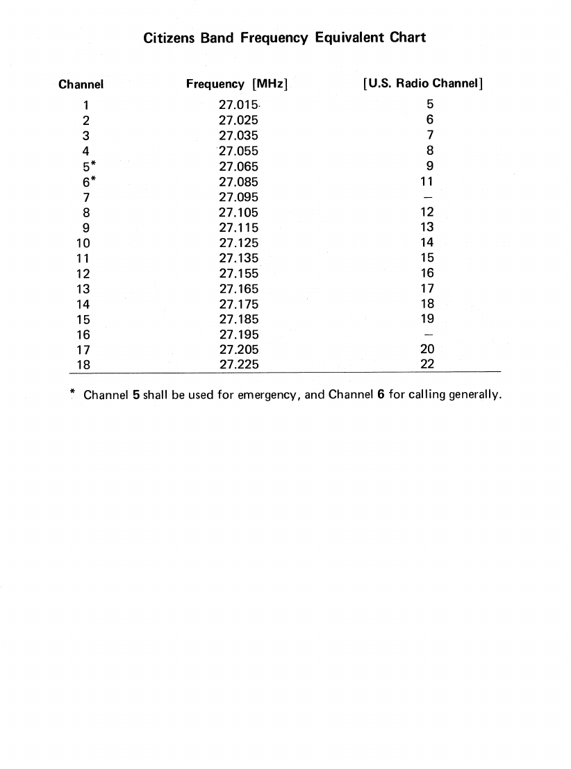
Citizens Band Frequency Equivalent Chart
Channel
Frequency [MHz]
[U.S. Radio Channel]
1
27.015.
5
2
27.025
6
3
27.035
7
4
27.055
8
5*
27.065
9
6
*
27.085
11
7
27.095
—
8
27.105
12
9
27.115
13
10
27.125
14
11
27.135
15
12
27.155
16
13
27.165
17
14
27.175
18
15
27.185
19
16
27.195
17
27.205
20
18
27.225
22
* Channel 5 shall be used for emergency, and Channel 6 for calling generally.

MATHEWS HARITOS PTY. LIMITED
HEAD OFFICE:
73 LAKEMBA STREET,
BELMORE 2192 NSW
TELEPHONE: (02) 750 6666
(KTAPOLO4XX1 126 Printed in Japan
This manual suits for next models
1
Popular Two-way Radio manuals by other brands

Harbor Freight Tools
Harbor Freight Tools 92078 Assembly and operating instructions

Floureon
Floureon M-880 User Manual and Instruction Guide

Motorola
Motorola APX4000 XH user guide

Motorola solutions
Motorola solutions RVA Series quick reference

Radioddity
Radioddity FS-T1 user manual

Vertex Standard
Vertex Standard VX-230 Series operating manual


 owner's manual")


