MHG Heating EcoStar 720 User manual
© MHG Heating Ltd
1
MHG Heating Ltd, Unit 4 Epsom Downs Metro Centre, Waterfield, Tadworth, Surrey, KT20 5LR
010612 Draft
Installation and Operating Manual for the
EcoStar 720 & 750 Oil Condensing Floor Standing Range
Output Range 20.0 – 62.0 kW

© MHG Heating Ltd
2
MHG Heating Ltd, Unit 4 Epsom Downs Metro Centre, Waterfield, Tadworth, Surrey, KT20 5LR
010612 Draft
Section
1.0 Appliance Type
3
1.1 EcoStar 720 High Efficiency 3
1.2 EcoStar 750 Condensing 3
2.0 Installation Regulations and Requirements 4
2.1 Appliance Warranties 5
3.0 Dimensions EcoStar 720 Range 6
3.1 Dimensions EcoStar 750 Range 6
3.6 Installation Clearances 7
4.0 Delivery, Mobility and Assembly 8
5.0 Technical Data 25
5.1 Fluing Options 26
6.0 Pressure Relief Valve 28
7.0 Electrical Connections 29
7.1 Internal Wiring Diagrams 31
8.0 Hydraulic Configurations 33
8.1 Hydraulic Single Unit 33
8.13 Hydraulic Cascade Unit 35
9.0 Filling The System 36
9.1 Pressure Vessel 37
10.0 System Water Quality 37
11.0 Appliance Controls 38
12.0 Appliance Fault Codes 38
13.0 Commissioning 100
13.1 Pre-Commissioning Checks. 100
13.2 Combustion System Commissioning 100
14.0 Routine Inspection and Servicing 101
14.1 Routine Service Inspection 101
14.2 Routine Cleaning and Maintenance 101
15.0 Weather Compensation Slope Graph and Sensor Curves 102
16.0 Optional System Controls 104
17.0 Exploded Spares Diagrams 105
18.0 Parts List 106
18.0 Installer / End Users Note 116
© MHG Heating Ltd
3
MHG Heating Ltd, Unit 4 Epsom Downs Metro Centre, Waterfield, Tadworth, Surrey, KT20 5LR
010612 Draft
1.0 Appliance Type
There are eight versions within the EcoStar 700 range. Each unit can be supplied with or without a
secondary condensing heat exchanger.
Please ensure you have the correct unit for the application prior to beginning the installation.
1.1 The EcoStar 720 High Efficiency unit without secondary condensing heat exchanger appliances are
designed to be applied to systems where there is not a need for a condensing boiler.
1.2 The EcoStar 750 Condensing unit with secondary condensing heat exchanger appliances are designed
to be applied to systems where the operating temperature of the system would benefit from the
application of a condensing boiler or a higher level of efficiency is required even though the systems
operating temperature is elevated.
The product codes for the standard range are:
Product Name Output kW Product Code
EcoStar 723 High Efficiency Boiler 28 94.10000-5423
EcoStar 753 Condensing Boiler 31 94.10000-5453
EcoStar 724 High Efficiency Boiler 37 94.10000-5424
EcoStar 754 Condensing Boiler 41 94.10000-5454
EcoStar 725 High Efficiency Boiler
45 94.10000-5425
EcoStar 755 Condensing Boiler 51 94.10000-5455
EcoStar 726 High Efficiency Boiler 56 94.10000-5426
EcoStar 756 Condensing Boiler 62 94.10000-5456
If a condensing EcoStar 753-756 boiler is being used the following flue and condensate connection kit is
also required.
Product Name Boiler Type
Product Code
Flue and Condensate Connection Kit 753 to 756 94.62200-4820

© MHG Heating Ltd
4
MHG Heating Ltd, Unit 4 Epsom Downs Metro Centre, Waterfield, Tadworth, Surrey, KT20 5LR
010612 Draft
2.0 Installation Regulations and Requirements
The installation of EcoStar 700 boilers must be in accordance with the relevant requirements of Gas Safety
(Installation & Use) Regulations 1994, Health & Safety at Work Act, Building Regulations, IEE Regulations,
Construction (Design & Management) Regulations 1994, Local Authority Bye-Laws, National, Fire
Regulations and Insurance Company requirements.
The following Codes of Practice are also applicable:-
BS 5440-1: 2000 Installation of flues and ventilation for gas appliances of rated input not exceeding 70
kW net (1st, 2nd and 3rd family gases).
Part 1: Specification for the installation of flues.
BS 5440-2: 2000 Installation of flues and ventilation for gas appliances of rated input not exceeding 70
kW net (1st, 2nd and 3rd family gases).
Part 2: Specification for installation and maintenance of ventilation for gas appliances.
BS 5449: 1990 Specification for forced circulation hot water central heating systems for domestic
premises.
BS 6644: 2005 Specification for gas fired hot water boilers of rated inputs between 70kW (net) and
1.8MW(net) (2nd and 3rd family gases).
BS 6798: 1987 Specification for installation of gas fired hot water boilers of rated input not exceeding 60
kW.
BS 6880: 1988 Code of Practice for low temperature hot water heating systems of output greater than
45kW. Parts 1, 2 & 3.
BS 6891: 1988 Specification for installation of low pressure gas pipework of up to 28mm (R1) in domestic
premises (2nd family gases)
BS 7593: 1992 Code of Practice for treatment of water in domestic hot water central heating systems.
BS 7671: 1992 Requirements for electrical installations. IEE Wiring Regulations. Sixteenth edition.
CISBE Guide reference sections B7, B11 and B13.
CP342 Part 2: 1974 Code of Practice for centralized hot water supply.
IGE/UP/2 Gas installation pipework, boosters and compressors on industrial and commercial premises.
IGE/UP/4 Commissioning of gas fired plant on industrial and commercial premises
IGE/UP/10 Installation of gas appliances in industrial and commercial premises. Part 1: Flued appliances.
The prevailing OFTEC regulations.
And any addition prevailing regulation and or code of practice not detailed above.

© MHG Heating Ltd
5
MHG Heating Ltd, Unit 4 Epsom Downs Metro Centre, Waterfield, Tadworth, Surrey, KT20 5LR
010612 Draft
2.1 Appliance Warranties
All MHG appliances enjoy a full 36 month warranty as detailed in our terms and conditions.
The guarantee period shall begin on the day of commissioning, or at latest 3 months after delivery has
been made.
The customer shall only be able to claim against MHG under guarantee if the commissioning of the object
of delivery has been carried out by MHG staff or the authorized supplier, if the customer has followed
MHG's instructions relating to the treatment and maintenance of the object of delivery, and if no
replacement parts of outside origin have been fitted.
Parts subject to wear such as ignition electrodes, seals etc. are strictly excluded from the guarantee.”
In addition to the above warranties, the Heat Exchangers carry a 60 month guarantee against
manufacturing or material defect.

© MHG Heating Ltd
6
MHG Heating Ltd, Unit 4 Epsom Downs Metro Centre, Waterfield, Tadworth, Surrey, KT20 5LR
010612 Draft
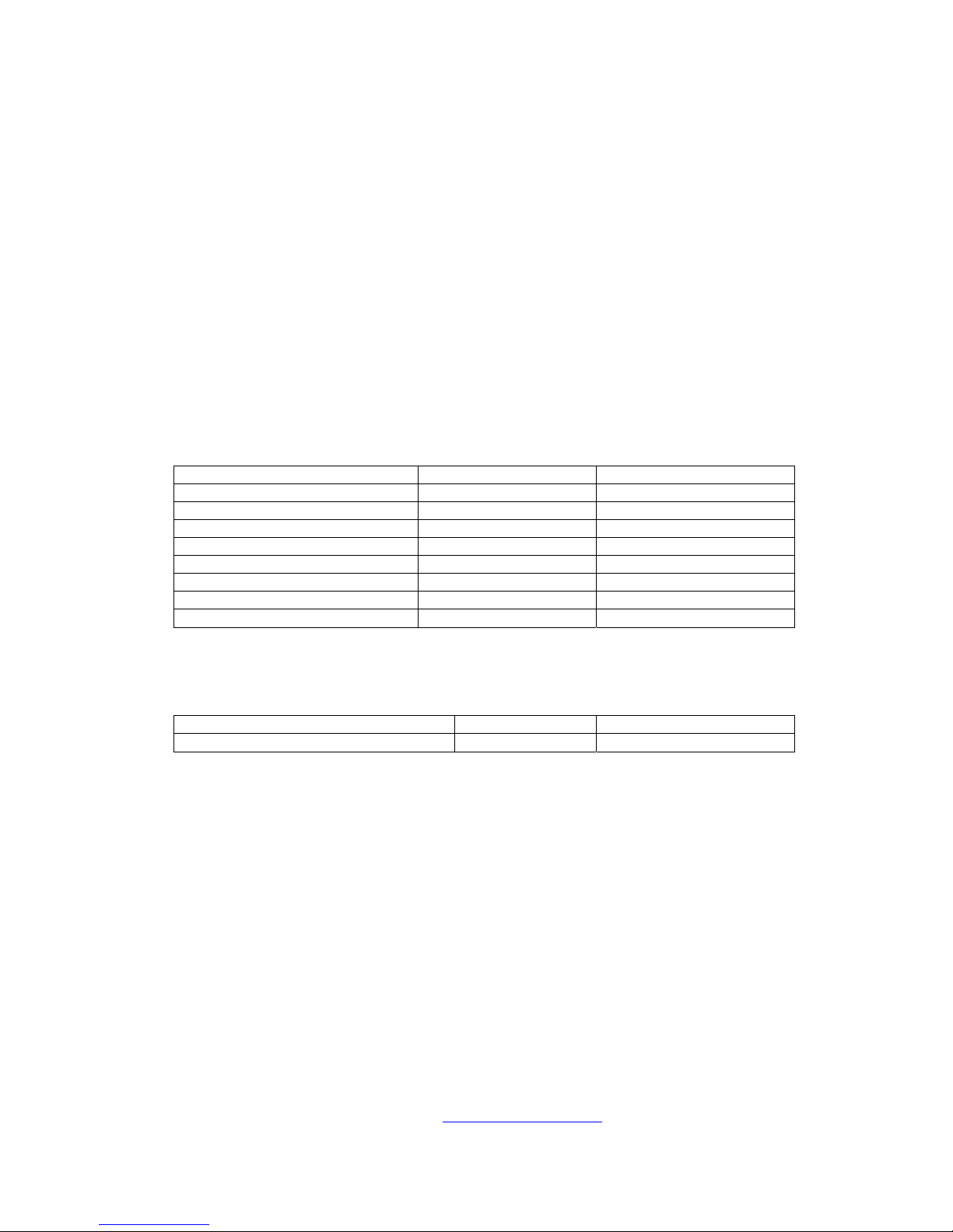
3.0 Dimensions. EcoStar 720
Item Description Units 723 724 725 726
Boiler Output (80/60) kW 27.8 37.0 45.4 55.6
A Initial Connection BSP 1
KFE Drain BSP ½
KSG Safety Set
L1 Overall Length mm 910 1040 1170 1300
L2 Support Separation mm 255 385 515 645
VL Flow Connection BSP 1 ½
RL Return Connection BSP 1 ½
Hydraulic Pressure Loss @ 20∆T mbar 10 12 13 14
Dry Weight kg 185 230 270 310
3.1 Dimensions. EcoStar 750
Item Description Units 753 754 755 756
Boiler Output (80/60) kW 28.8 38.5 47.1 57.7
Boiler Output (50/30) kW 31.0 41.4 50.7 62.1
A Initial Connection BSP 1
KFE Drain BSP ½
KSG Safety Set
L1 Overall Length mm 1290 1420 1550 1680
L2 Support Separation mm 255 385 515 645
VL Flow Connection (Pump Kit) BSP 2
RL Return Connection (Pump Kit) BSP 2
Hydraulic Pressure Loss @ 20∆T mbar 50 52 53 54
Dry Weight kg 205 250 290 330
© MHG Heating Ltd
7
MHG Heating Ltd, Unit 4 Epsom Downs Metro Centre, Waterfield, Tadworth, Surrey, KT20 5LR
010612 Draft
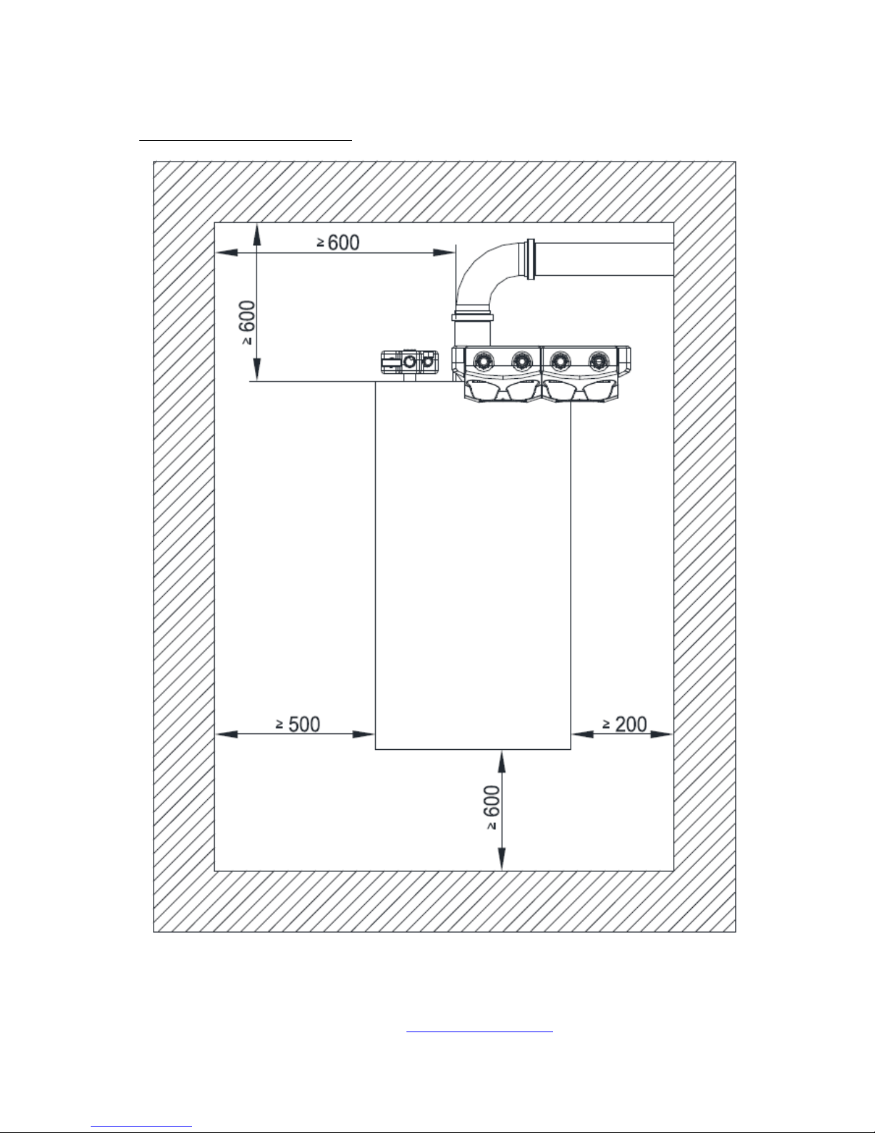
3.6 Installation and Service Clearances
© MHG Heating Ltd
8
MHG Heating Ltd, Unit 4 Epsom Downs Metro Centre, Waterfield, Tadworth, Surrey, KT20 5LR
010612 Draft
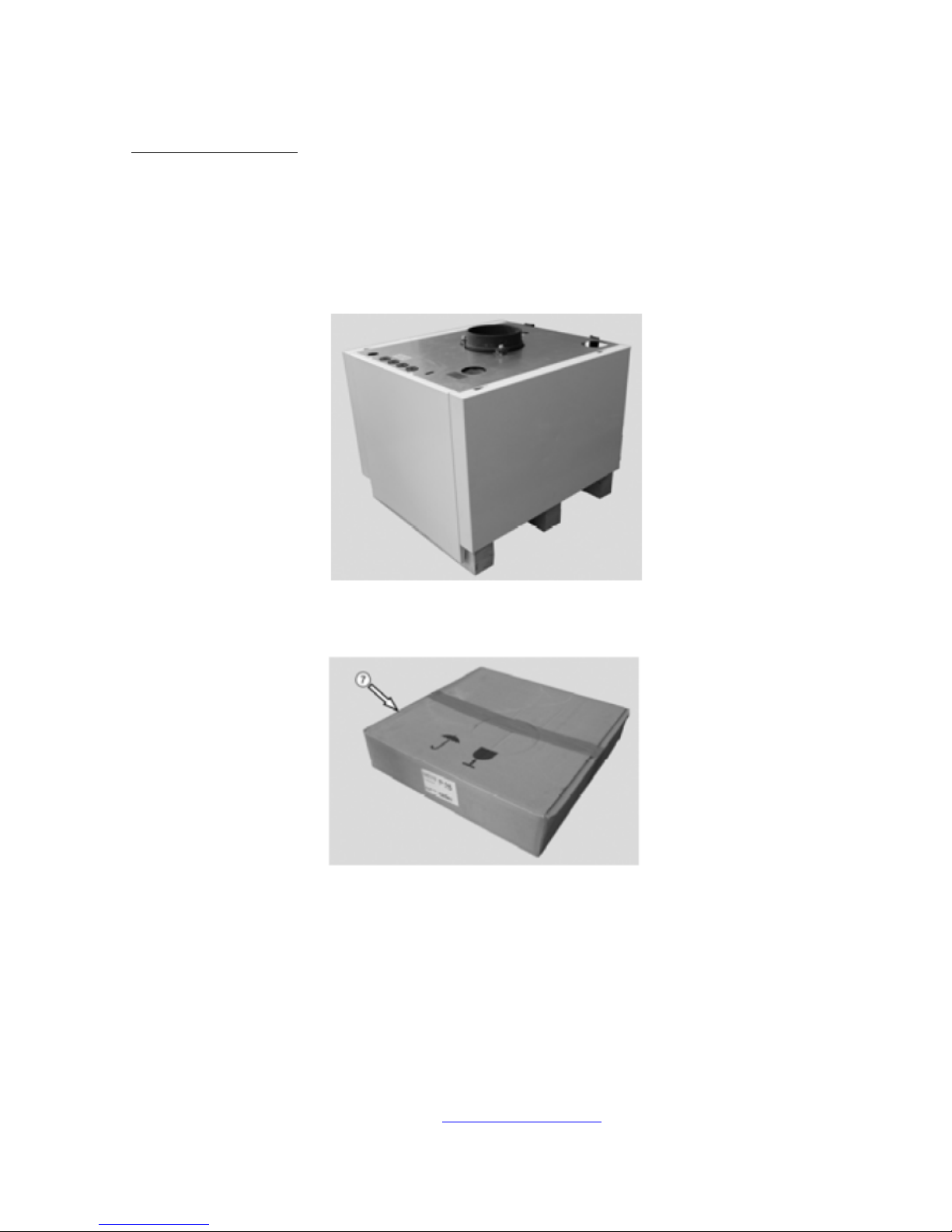
4.0 Delivery and Mobility
All EcoStar 700s are supplied fully tested and therefore may contain residual test water.
The test water utilised contains additives that will help prevent associated pumps from sticking and other
metals from oxidising.
To maintain the structural integrity of the appliance the internal components should not be used during
the lifting and positioning of the unit.
EcoStar 700 Primary Heat Exchanger on transport pallet.
Boiler door carton.

© MHG Heating Ltd
9
MHG Heating Ltd, Unit 4 Epsom Downs Metro Centre, Waterfield, Tadworth, Surrey, KT20 5LR
010612 Draft
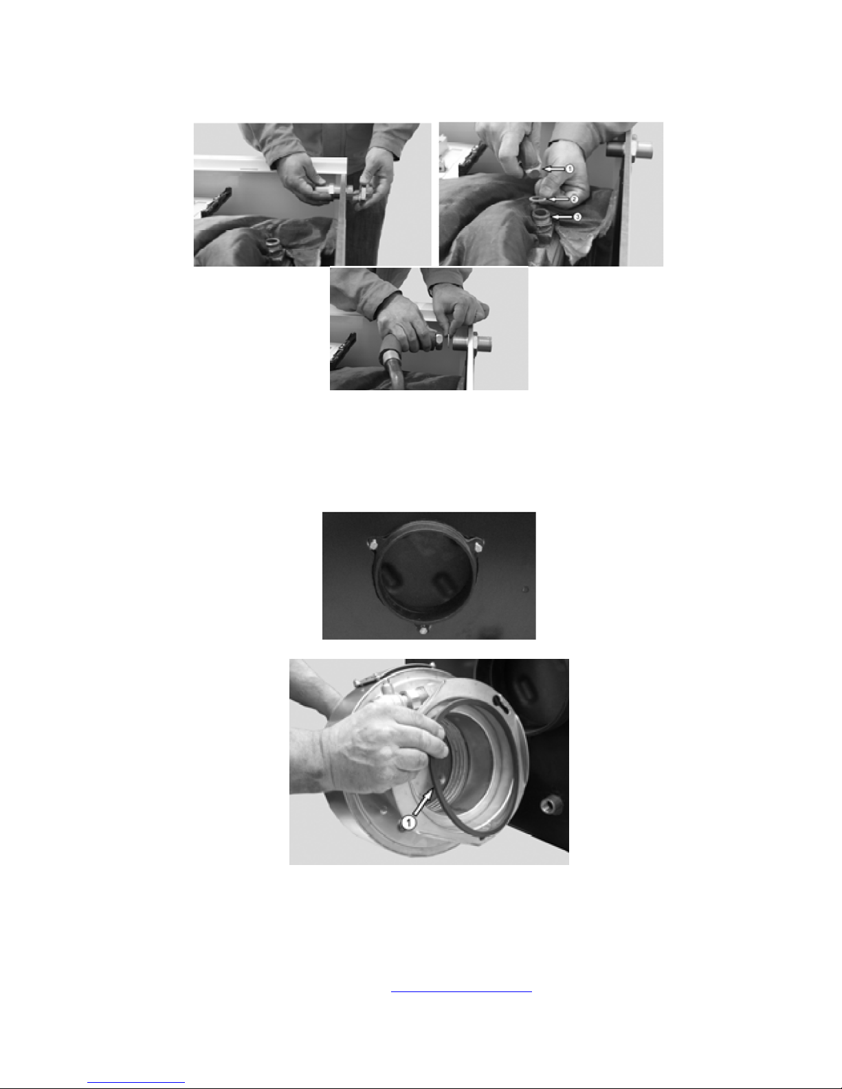
The initial connections to the primary heat exchanger flow and return connections can be made with the
heat exchanger on the transport pallet.
1 & 2. Flow & Return 1.5”
3. Drain
If the secondary heat exchanger is being applied the interconnecting pipes and adapters can also be
applied.
Prior to positioning the primary heat exchanger on to its feet it is advisable to remove the casing panels.

© MHG Heating Ltd
10
MHG Heating Ltd, Unit 4 Epsom Downs Metro Centre, Waterfield, Tadworth, Surrey, KT20 5LR
010612 Draft
Once correctly positioned install the baffles as indicated above.
723-725 & 753-755 726 & 756
Baffle type 1 Yes No
Baffle type 2 Yes Yes

© MHG Heating Ltd
11
MHG Heating Ltd, Unit 4 Epsom Downs Metro Centre, Waterfield, Tadworth, Surrey, KT20 5LR
010612 Draft
Fit the door mounting hinge 1 on the required side and the blanking plate 2 on the other.
The arrowed items provide information relating to the location of the heat exchangers support legs.
Once the primary heat exchanger is in position the side cases can be reattached.
Install the double nipple to the top rear of the primary heat exchanger. This provides a connection point
for the pressure relief valve, pressure gauge and automatic air released group.
© MHG Heating Ltd
12
MHG Heating Ltd, Unit 4 Epsom Downs Metro Centre, Waterfield, Tadworth, Surrey, KT20 5LR
010612 Draft
Install the case transition section and interconnection pipework and seals.
When installing a 720 range appliance the flue can be connected directly to the DN180 flue spigot.
When installing a 750 range appliance the secondary heat exchanger must connected to the primary heat
exchanger flue outlet spigot.
Install the seal 1 into the recess of the secondary heat exchanger.

© MHG Heating Ltd
13
MHG Heating Ltd, Unit 4 Epsom Downs Metro Centre, Waterfield, Tadworth, Surrey, KT20 5LR
010612 Draft
Ensure that the vent plug is in place, tight and closed.
Install the seals and associated adapted fittings.
Mounted secondary heat exchanger.
Install the return connector from the secondary heat exchanger to the primary heat exchanger and the
common return pipe to the rear casing.
© MHG Heating Ltd
14
MHG Heating Ltd, Unit 4 Epsom Downs Metro Centre, Waterfield, Tadworth, Surrey, KT20 5LR
010612 Draft
Following the installation of the rear casing section the system pipework or pump group pipework can be
installed.
If a MHG pump group is being used, install the associated pipework.
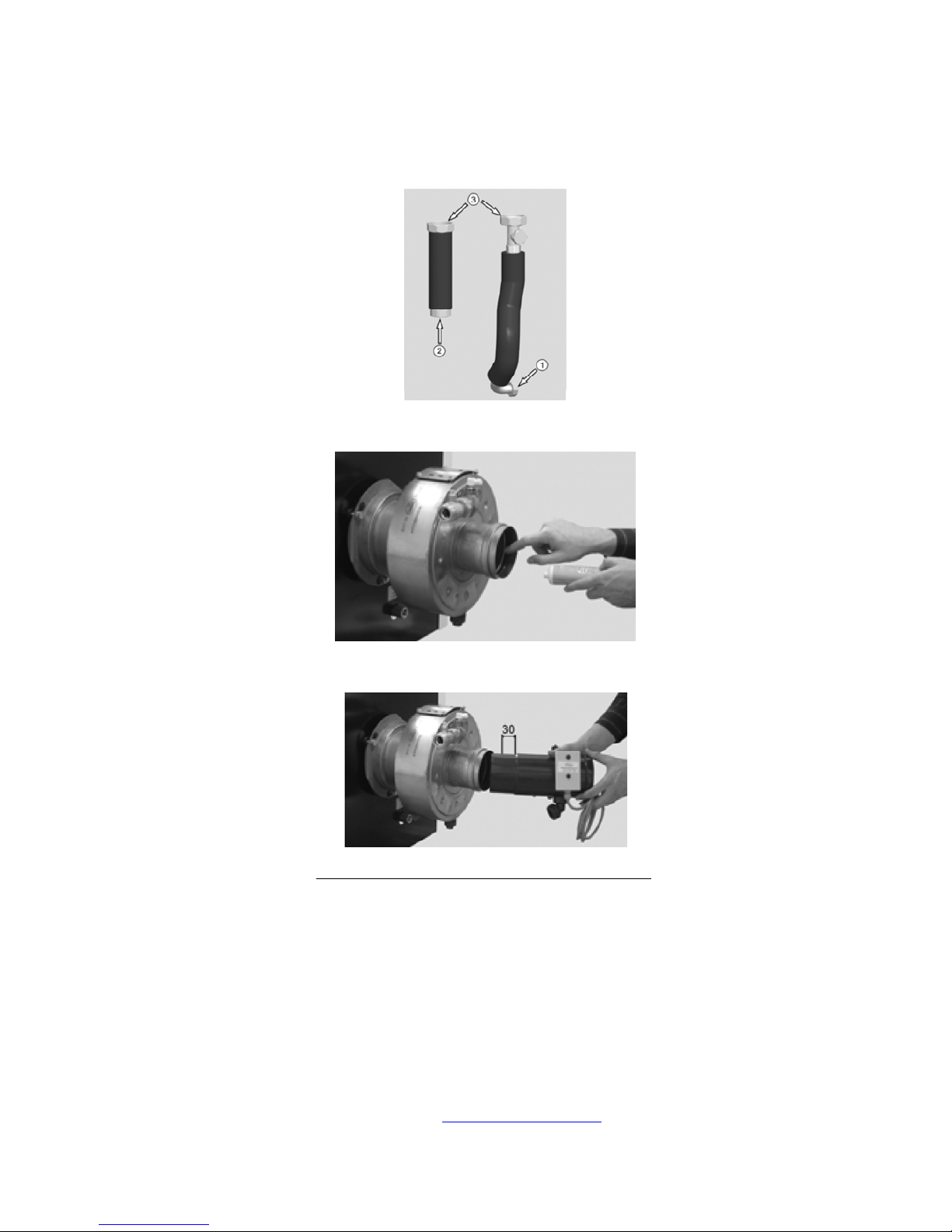
Prior to installing any flue component ensure that the seal has been lubricated with a silicone grease.
Flue and condensate connection kit 94.62200-4820
When installing the first section of flue section into the secondary heat exchanger ensure that the male
section is only inserted a maximum of 30mm.
The flue limit sensor section has a definitive shoulder, whereas a DN100 elbow can be over inserted and
restrict the flue way.
© MHG Heating Ltd
15
MHG Heating Ltd, Unit 4 Epsom Downs Metro Centre, Waterfield, Tadworth, Surrey, KT20 5LR
010612 Draft
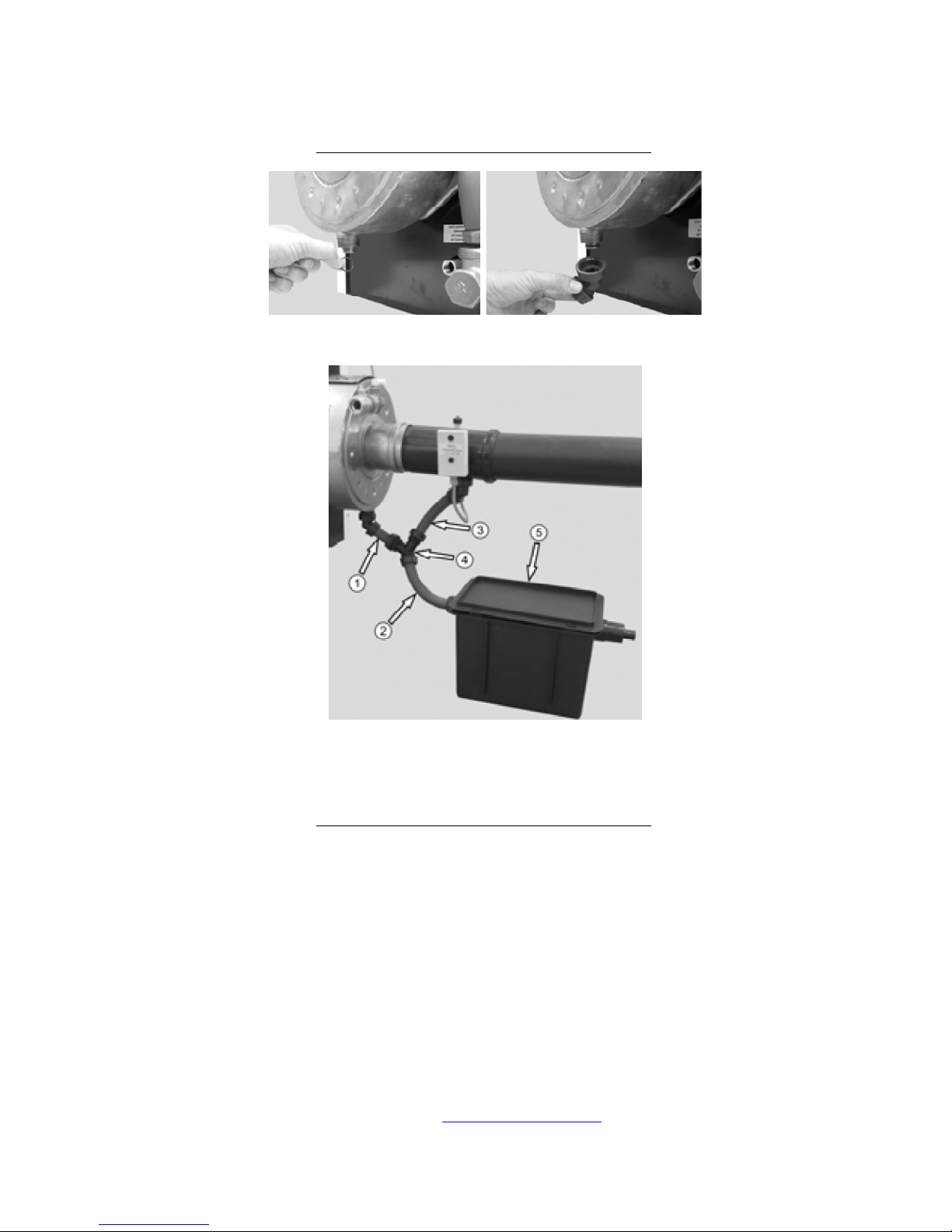
Flue and condensate connection kit 94.62200-4820
Ensure that all seals are installed in the condensate waste system.
1.Heat Exchanger drain. 2. Combined drain, 3. Flue system drain,
4. Y connector, 5. Neutralizing unit.
Flue and condensate connection kit 94.62200-4820
© MHG Heating Ltd
16
MHG Heating Ltd, Unit 4 Epsom Downs Metro Centre, Waterfield, Tadworth, Surrey, KT20 5LR
010612 Draft
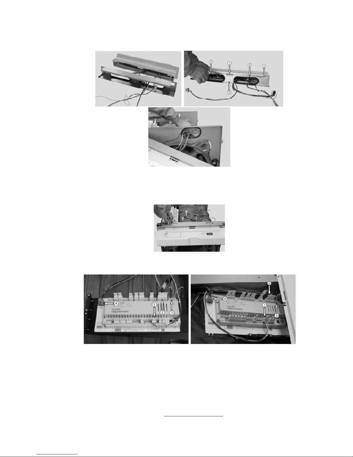
Install the fascia onto the inner mounting frame ensuring that the wires and phials are not
snagged.
The control is secured with a combination of hanging lugs 1 and screws 2.
Attach the inner frame to the inner front frame.
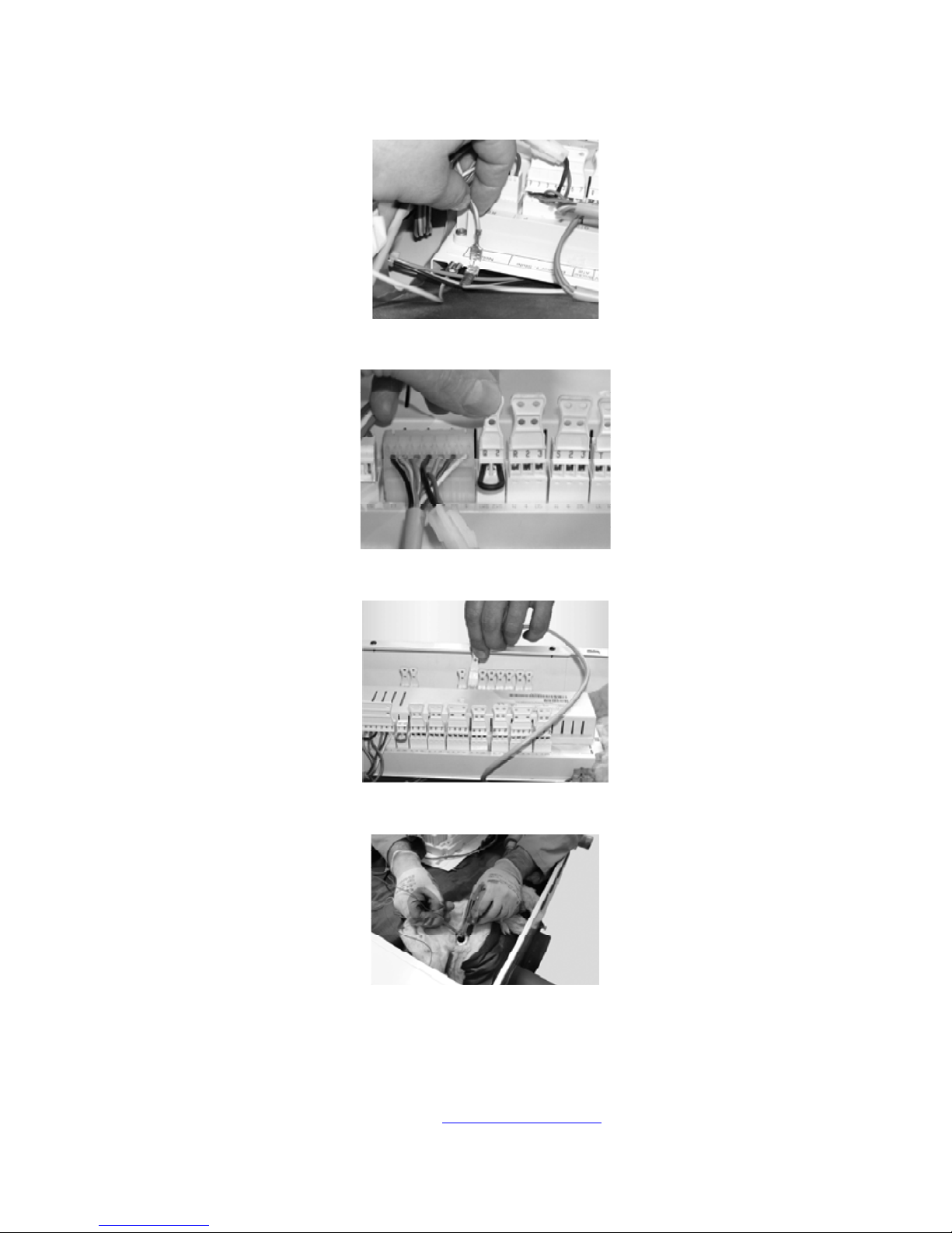
Connect the fascia wiring to the frame mounted RVS controller.
1. QAA75 connection G+ CL- CL+
2. Burner control connection
3. RVS Power supply connection
4. Permanent power supply connection.
© MHG Heating Ltd
17
MHG Heating Ltd, Unit 4 Epsom Downs Metro Centre, Waterfield, Tadworth, Surrey, KT20 5LR
010612 Draft
Ensure that all Earthing straps are securely applied.
Install the Flue Limit Thermostat wiring. SK1 / SK2
Attached the boiler controller sensor to connection to B2/M
Install the boiler control sensor and limit thermostat phial into the pocket located in the casting adjacent
to the flow connection.

© MHG Heating Ltd
18
MHG Heating Ltd, Unit 4 Epsom Downs Metro Centre, Waterfield, Tadworth, Surrey, KT20 5LR
010612 Draft
Install the connecting pipework and safety group and drain valve.

© MHG Heating Ltd
19
MHG Heating Ltd, Unit 4 Epsom Downs Metro Centre, Waterfield, Tadworth, Surrey, KT20 5LR
010612 Draft
Install the burner mounting bolts and combustion chamber pressure test point onto the boiler door.
Mount the boiler door onto the hinge and ensure correct alignment when closed.
Leave the door open to ensure correct insertion of the burner.
Please refer to the burner technical manual for further guidance.
Once this has been achieved the burner door can be closed and the burner reattached.
Connect the electrical Wieland plug to the burner.

© MHG Heating Ltd
20
MHG Heating Ltd, Unit 4 Epsom Downs Metro Centre, Waterfield, Tadworth, Surrey, KT20 5LR
010612 Draft
Once all electrical and operational checks have been completed the top case can be installed and secured.
Please refer to the following sections for electrical connections and commissioning guidance.
This manual suits for next models
1
Table of contents


