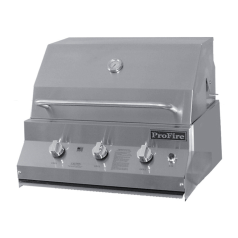
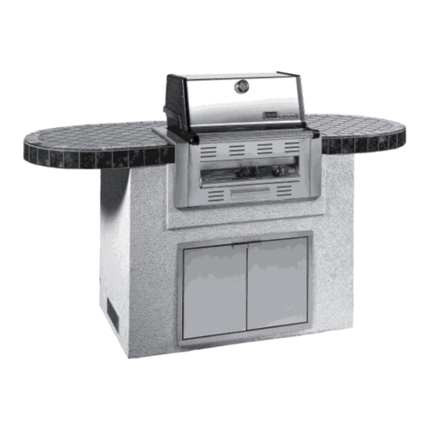
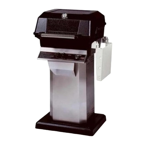
MHP JNR User manual

www.mhpgrills.com 1
JNR GAS GRILL HEAD
Assembly Manual
SCAN THE
QR CODE FOR
ASSEMBLY VIDEO English

2
DANGER: IF YOU SMELL GAS
1. Shut off the main gas supply to the grill
2. Extinguish any open flame
3. Open lid
4. If odor continues, keep away from the grill and
immediately call your gas supplier or your fire department.
Failure to follow these instructions could result
in fire or explosion which could cause property
damage, personal injury or death.
WARNING: FOR YOUR SAFETY
1. Do not store or use gasoline or other flammable liquids or
vapors in the vicinity of this or any other appliance
2. An LP cylinder not connected for use should not be stored
in the vicinity of this or any other appliance.
3. Follow all leak-test procedures on page 10 of this manual
carefully before using. Do this even if the grill was dealer
assembled. Do not test for leaks with a match or any
open flame. Do not try to light this grill without reading
the “Lighting” instructions.
The appliance is FOR OUTDOOR USE ONLY. It is not to be used inside a
garage, other building or any type of enclosed area. Combustible materials
should never be within 18 inches of the bottom, back or sides of your MHP
Gas Barbecue Grill.
•The JNR Grill head is specifically designed to fit these MHP mounting options.
- JC4 Four Legged Open Cart - OCOL/OCOLB with OM Base
- MPP In-ground Post - OCOL/OCOLB with OP Base
- MPB Patio/Deck Base - OCOL/OCOLB with OC Base
•The gas supply may be either LP or Natural Gas
BOXES/BAGS:
IMPORTANT SAFETY WARNINGS
TOOLS LIST:
ADJUSTABLE WRENCH 3/4" COMBINATION
WRENCH
7/16" COMBINATION
WRENCH (2)
3/8" COMBINATION
WRENCH
PHILLIPS
SCREWDRIVER
HH-GRATE-SS
Briquette Grate
JNR-LP
Control Panel for LP Gas Grill
(includes hose and regulator)
sJNR-SEAR-PK
SearMagic Cooking Grids
OWNER'S MANUAL BAG
Includes:
• Owner's Manual
• Temperature Gauge
• Venturi Tube Cleaner
• (2) Lid Pivot Pins
s
HH-SS-GRID2
Stainless Steel Cooking Grid
HHDDSK
Side Shelf Kit
BRIQUETTE BAG
53 Briquettes
END CAPS/HANDLE
Includes hardware
JNR-NAT
Control Panel for Natural Gas Grill
You should have the following boxes/bags containing the different parts and hardware needed to assemble your grill.
OR OR
Make sure your base is
assembled before continuing.
The base assembly instructions
should be included with your base.
Visit our website mhpgrills.com/
info/owners-manuals/
for a complete list of assembly
videos & manuals

www.mhpgrills.com 3
Remove the Burner
•Remove the grill burner by taking out
the two small cotter pins located on the
underside of the bottom grill casting (fig. a)
•Pull the burner up and out of the
grill head (fig. b).
ASSEMBLY PREPARATION
Choose a Location where you are going to set up your grill. Make sure
there is enough room and you have a flat surface. Improper assembly
may be dangerous. Please carefully follow the assembly instructions in
this manual.
•Place the box facing up
•Remove the packaging material followed by the grill head components
•Set the components on a flat surface
•Check to see if all components are included and that you
have the appropriate tools to begin the assembly. Remove all
components and discard the box.
At this point you should already have your bottom casting attached to your
mounting (See your mounting assembly manual for these steps).
Make sure your base is assembled before continuing. The base assembly
instructions should be included with your base.
Visit our website mhpgrills.com/info/owners-manuals/ for a complete list of
assembly videos & manuals
s
CONTINUED
CONTROL PANEL
ASSEMBLY
KEP NUTS (6)
BRACKETS (2)
JNR-LP
Control Panel for LP Gas Grill
(includes hose and regulator)
JNR-NAT
Control Panel for Natural
Gas Grill
PARTS INCLUDED IN BOX:
PUSH BUTTONPHILLIPS HEAD
BOLTS
(2)
(2)
BATTERY VENTURI
CLEANER
KNOBS (2) LP GAS HOSE &
REGULATOR
Included with
LP Gas Grills only
(pre-attached)
INSTALLING THE CONTROL PANEL
STEP 1
PHILLIPS
SCREWDRIVER
7/16" COMBINATION
WRENCH
TOOLS NEEDED:
fig. a
fig. b

4
Attaching the Control Panel Assembly to the Front of
the Bottom Casting
•Attach the complete control panel assembly to the front
of the grill bottom casting with two 1/4-20 Kep Nuts and
hand tighten
•Make sure the valve orifices on the control panel align
with the burner venturi correctly and that the venturi tubes
go over the valve orifices at least 1/4" to 3/8". (see Valve
Stem Engagement below)
•Tighten all nuts using a 7/16" combination wrench
INSTALLING THE CONTROL PANEL, CONTINUED
STEP 1
Connecting the Control Panel Support Brackets
Two support brackets are connected beneath the control panel
to the grill bottom casting for added support.
• Push 1/4 - 20 x 1-1/4" Phillips Head Bolts down through the
grill bottom casting from the inside and continue through the
back hole on the support brackets. Secure the brackets with
1/4 - 20 Kep Nuts.
• Attach the control panel to the support brackets by pushing up
a 1/4 - 20 x 1/2" Phillips Head Bolt through the front hole of each
support bracket and the lower lip of the control panel. Fasten
brackets with a 1/4-20 Kep Nut.
•Tighten all nuts using a screwdriver and a 7/16" combination wrench
Venturi Engagement
At the top end of each valve there is a tiny
gas opening known as the orifice. Gas exits
the orifice and enters a venturi where it mixes
with air coming in from the side air shutter.
The proper mixture of air and gas produces
a clean blue flame at the burner.
Make sure the valve orifice on the control
panel aligns with the burner venturi tube
correctly. The orifice should fit into the
venturi tube 1/4" to 3/8".
1/4-20 x 1/2"
PHILLIP
HEAD BOLT
1/4-20 x 1/2"
PHILLIP
HEAD BOLT
1/4-20"
KEP NUT
1/4-20"
KEP NUT
SHELF
BRACKETS
Reinstall the Burner
•Drop the burner into the bottom of the
grill casting making sure the venturi tubes
go through the bottom opening.
•The burner leg pins pins should align with
the predrilled holes in the bottom of the
grill pit.
•Reattach small cotter pins onto the
burner leg pins
OPENING FOR
VENTURI TUBES
COTTER PIN
LEG PIN
HOLES
CORRECT INCORRECT

www.mhpgrills.com 5
INSTALLING THE CONTROL PANEL, CONTINUED
STEP 1
Ignitor Wire Connection
Attach the wire from the ignitor
module, located behind the
control panel, to the porcelain
insulator found on the underside
of the bottom casting.
Be careful not to crack the
delicate porcelain insulator
Battery Installation
•Place the AAA battery "+" side down into the ignitor
module.
•Install push button over the battery and turn clockwise
to tighten in place.
Attach Knobs to Control Panel
Attach the two control knobs to the grill by pushing them
down securely onto the valve stems.
Connect the Gas Supply
Please reference the assembly manual that came with your grill mounting for directions on connecting the gas
supply to your grill.
+
-
IGNITOR MODULE
PORCELAIN INSULATOR

6
INSTALLING THE SIDE SHELF
STEP 2
Mount Side Shelf Brackets
•Shelf can be mounted to left or right side of grill
•Locate the side brackets and mount the brackets to the
side of the grill.
•Attach the brackets using the supplied Phillips Head Bolts and
Kep Nuts (2 Phillips Head Bolts and Kep Nuts per bracket).
•Insert the Phillips Head Bolts into the pre-drilled holes from
the inside of the bottom casting and attach the Kep Nuts
on the outside.
•Tighten the Kep Nuts while making sure the brackets
remain parallel with the grill using a screwdriver and
a 7/16" combination wrench.
Attach the Side Shelf
Once both brackets are in place, attach the Side Shelf.
•Place the left bottom shelf threaded screw into the left bottom
bracket slot.
•Gently spread the shelf apart to insert the right bottom shelf
threaded screw into the right bottom bracket slot.
•Tighten Nylock Nuts on the bottom threaded screws using
a screwdriver and a 3/8" combination wrench. Make sure
the nuts are snug but do not restrict movement of folding and
unfolding of the shelf.
Top threaded screws on shelf do NOT use nuts.
Remove Plastic Protective Sticker
Before installing the side shelf, remove the plastic protective sticker from
all sides of the shelf and shelf brackets.
SHELF
KEP NUTS (4) NYLOCK NUT (2)
SIDE BRACKETS (2) PHILLIPS HEAD
BOLTS (4)
PARTS INCLUDED IN BOX:
HHDDSK
Side Shelf Kit
7/16"
COMBINATION
WRENCH
3/8"
COMBINATION
WRENCH
PHILLIPS
SCREWDRIVER
TOOLS NEEDED:

www.mhpgrills.com 7
INSTALLING THE BRIQUETTE GRATE
STEP 3
Install the Stainless
Steel Briquette Grate
by placing it into the
bottom grill casting.
The grate should
rest level on the
shelf edge just
above the burner.
STAINLESS STEEL
BRIQUETTE GRATE
PARTS INCLUDED IN BOX:
HH-GRATE-SS
Briquette Grate
INSTALLING THE BRIQUETTES
STEP 4
•Place the porcelain briquettes on top of the grate.
•Place one at a time
•Carefully place the porcelain briquettes on the
grate in the pattern shown making sure to only
have one layer.
•This pattern helps to distribute heat evenly and
reduce flare-ups.
The bag includes 53 briquettes—you will need
all 53 to fill the briquette grate properly.
BRIQUETTE BAG
53 Briquettes
ATTACHING THE TOP CASTING
STEP 5
Attach the Top Casting
•Locate the top casting for your grill and place it on the back
of the bottom casting, aligning the two back hinges.
•Slide the Lid Pivot Pin through both hinge holes and secure
with a Hitch Pin.
•Repeat on opposite side.
LID PIVOT PINS HITCH PINS
PARTS NEEDED:
OWNER'S MANUAL BAG
You will find the parts you need
in the bag with your owner's
Manual
It is recommended
someone assist you
with this step.

8
Install one end cap first, followed by the center shaft handle,
then enclose it by securing the second end cap.
Attaching the Handle
•Attach the first end cap to the grill lid using a 1/4-20 x 1-1/2"
Hex Bolt and Kep Nut making sure that the Graphite Gasket
(purple element) is positioned between the end cap and
the grill lid as shown.
•Tighten the end cap by using two 7/16" Combination Wrenches—
one to hold the bolt head and one to tighten the Kep Nut.
•Insert the handle into both the installed end cap and second
end cap
•Installl the second end cap using the same method
as outlined above.
ATTACHING THE FRONT HANDLE
STEP 6
HANDLE END CAP ASSEMBLY (2)
Each End Cap Includes:
• End Cap
• Graphite Gasket
• 1/4-20 x 1-1/2" Hex Bolt
• Kep Nut
PARTS INCLUDED IN BOX:
END CAPS/HANDLE
Includes hardware
Installing the Temperature Gauge
•Insert the temperature gauge through
one washer into the pre-drilled hole
on the grill top casting making sure
the gauge is facing outward.
•On the inside of the grill lid, install
the second washer, then the Wing Nut
to the temperature gauge post.
•Hand tighthen the Wing Nut until
temperature gauge is snug against
the casting.
INSTALLING THE TEMPERATURE GAUGE
STEP 7
TEMPERATURE GAUGE ASSEMBLY
Includes:
• Temperature Gauge
• Washer (2)
• Wing Nut
PARTS NEEDED:
OWNER'S MANUAL BAG
The Temperature Gauge
is included in the
Owner's Manual bag
TEMPERATURE
GAUGE
PRE-DRILLED HOLE FOR
TEMPERATURE GAUGE
END CAPS
GRAPHITE GASKETS
WASHER
WING NUT
WASHER
TOOLS NEEDED:
7/16" COMBINATION
WRENCH (2)

www.mhpgrills.com 9
STAINLESS STEEL COOKING GRIDS (2) SEARMAGIC COOKING GRIDS (2) GRID CLEANING TOOL
(GGWB5)
PARTS INCLUDED
HH-SS-GRID2 BOX:
PARTS INCLUDED
JNR-SEAR-PK BOX:
JNR-SEAR-PK
SearMagic Cooking Grids
HH-SS-GRID2
Stainless Steel
Cooking Grid
OR
ADDING THE STAINLESS STEEL OR SEARMAGIC COOKING GRIDS
STEP 8
Installing Stainless Steel Cooking Grids
•The two stainless steel cooking grids should easily
drop in side-by-side above both briquette grate and
porcelain briquettes
•The top side of the Stainless Steel Grids has
the rods on top of the frame.
Installing SearMagic Cooking Grids
•The two SearMagic cooking grids should easily drop
in side-by-side above both the briquette grate and the
porcelain briquettes.
•The SearMagic Grids are reversible. Use the ribbed side
for making sear marks on steaks and use the smooth
side for more delicate items.
ADDING THE WARMING RACK
STEP 9
Installing the JNR Warming Rack
•Rest the warming rack on the notches located in the back top edge of the
bottom casting.
•The top side of the warming rack has the rods on top of the frame.
WARMING RACK
PART INCLUDED:
HHSSTS
Warming Rack REST WARMING RACK
ON NOTCHES

10
ATTACHING TO GAS LINE
LEAK TESTING
Do not make sharp bends when bending your flexible
stainless-steel tubing to match the feed of your grill
valve and position in the top notch of the post.
The LP Hose and Regulator is factory installed on your
control panel. Make sure the LP hose runs through
the hose retention notch or clip (depending on your
specific grill mounting). For additional information,
reference your grill mounting assembly manual.
FOR NATURAL GAS & HARD-PLUMBED LP GAS
INSTALLATIONS
BENDING STAINLESS STEEL TUBING
FOR LP GAS INSTALLATIONS
After you have successfully assembled your grill—hook up your gas lines and check all connections.
For complete steps on connecting your grill to a gas line please refer to the instructions included
in the assembly manual for your specific mounting.
LEAK TEST ALL GAS CONNECTIONS BEFORE USING YOUR GRILL.
DO NOT SMOKE WHILE LEAK TESTING.
DO NOT LEAK TEST WITH A MATCH OR OPEN FLAME.
DO NOT USE A GRILL THAT IS LEAKING GAS.
YOU SHOULD TEST FOR GAS LEAKS EVERY TIME YOU
DISCONNECT AND RECONNECT A GAS FITTING.
PERFORM A LEAK TEST EVEN IF YOUR GRILL WAS DEALER
OR STORE ASSEMBLED.
DO NOT IGNITE BURNERS WHEN LEAK TESTING.
LEAK TESTING STEPS
1. Grill burner control valves should be turned off and
the gas turned on at source.
2. Apply soap solution to all gas connections.
To make soap solution, mix together equal amounts
of liquid detergent and water.
3. Soap bubbles will appear if there is a leak.
4. Tighten the connection using a 3/4" combination
wrench and adjustable wrench to make the proper
seal (one wrench is used to hold the fitting while the
other is used to tighten). Recheck for soap bubbles.
If a leak is detected…
If you have detected a leak
try tightening and securing all
connections. The use of two
wrenches is recommended—
one wrench is used to hold
fitting while the other is used
to tighten.
vFor LP models, leak test with a full propane cylinder.
vFor systems other than self-contained LP cylinders:
•The grill and its individual shut-off valve must be
disconnected from the gas supply piping systems
during any pressure testing of that system at test
pressures in excess of 1/2 psi (3.5 kPa).
•The grill must be isolated from the gas supply piping
system by closing its own manual shut off valve during
any pressure testing of the gas supply piping system at
pressures equal to or less than 1/2 psi (3.5 kPa).

www.mhpgrills.com 11
Enhance Your Grill
Our premium accessories have been designed specifically for our grills
with quality materials and craftsmanship
Visit your local dealer or our online store
www.mhponlinestore.com
Protect Your Grill
Our grill covers are constructed of a durable polyester lined vinyl,
designed to protect your grills from the elements.
STAINLESS STEEL SIDE BURNER
The premium commercial grade stainless steel
side burner is 12,000 BTU rated, has its own
electronic ignition, and is factory assembled for
simple bolt-on installation. Available for both
Natural and LP Gas.
SBA3-N (Natural Gas) | SBA3-P (LP Gas)
ROTISSERIE KIT
Rotisserie Kit includes RO6 stainless
steel motor, motor mounting bracket,
rotisserie rod, handle, bushing, forks
and 3 ft. cord. Max. 25 lb. balanced load.
RKMHP
Mid-Length Grill Cover
Side Shelf Up
HHCVPREM
Full-Length Grill Cover
Side Shelf Up
CV2PREM
Full-Length Grill Cover
Side Shelf Down
DDCVPREM

12
TECHNICAL SUPPORT
© MHP 2020, All Rights Reserved
By
ProFire
DRAGON
FIRE
Family Owned & Operated Since 1957 AM-JNR-0321
Modern Home Products
150 S. Ram Road • Antioch, IL 60002
847.395.6556 • 888.647.4745
Make the most out of your grilling experience!
From side burners and rotisseries to grill covers and more—
we carry a complete line of grill upgrades, accessories and grill parts
designed specifically for your MHP Grill.
rVisit MHPGrills.com for more information
California Proposition 65 Warning: This product can expose you to chemicals including Chromium (hexavalent compounds),
which are known to the State of California to cause cancer and birth defects or other reproductive harm. For more information go to:
www.P65Warnings.ca.gov.
DON'T FORGET TO REGISTER YOUR GRILL!
It is the responsibility of the grill owner to complete and submit the warranty registration
form to MHP in order for the warranty to be valid.
What you will need to register your grill:
•A bill of sale, canceled check, or payment record is
required to verify the purchase date and establish
warranty period.
•Model Number
•Serial Number
•Type of Grill Purchased (Natural or LP Gas)
How to find your grill model #/serial #
The model number tag is located on the left end cap of the control panel.
Visit mhpgrillpartsonline.com/warranty-registration-form/
to register your grill online. A mail-in registration postcard is also included
with your owner's manual.
YOUR MODEL #: JNR YOUR SERIAL #:
Other manuals for JNR
1
Table of contents
Other MHP Grill manuals
Popular Grill manuals by other brands
BBQ
BBQ Grillware 164826 owner's manual

YAKINIKU
YAKINIKU SHICHIRIN instruction manual
Rational
Rational iVario 2-XS Original Installation Instructions
Jumbuck
Jumbuck GEN-SE-25T quick start guide
Anvil
Anvil GGA3004 R04 Installation, Operation and Care Manual

Garland
Garland XE24 Installation, operating & service instructions
Uniflame
Uniflame Outdoor Charcoal Barbecue Grill CBC701W owner's manual
Fagor
Fagor SE 60 Instruction manual for installation and use

Philips
Philips HD6320 quick start guide

Lakeland
Lakeland 16906 Instruction booklet
Cadac
Cadac Meridian 3 Woody Assembly instructions

Aussie
Aussie Koala 7900 Series Assembly and use manual
