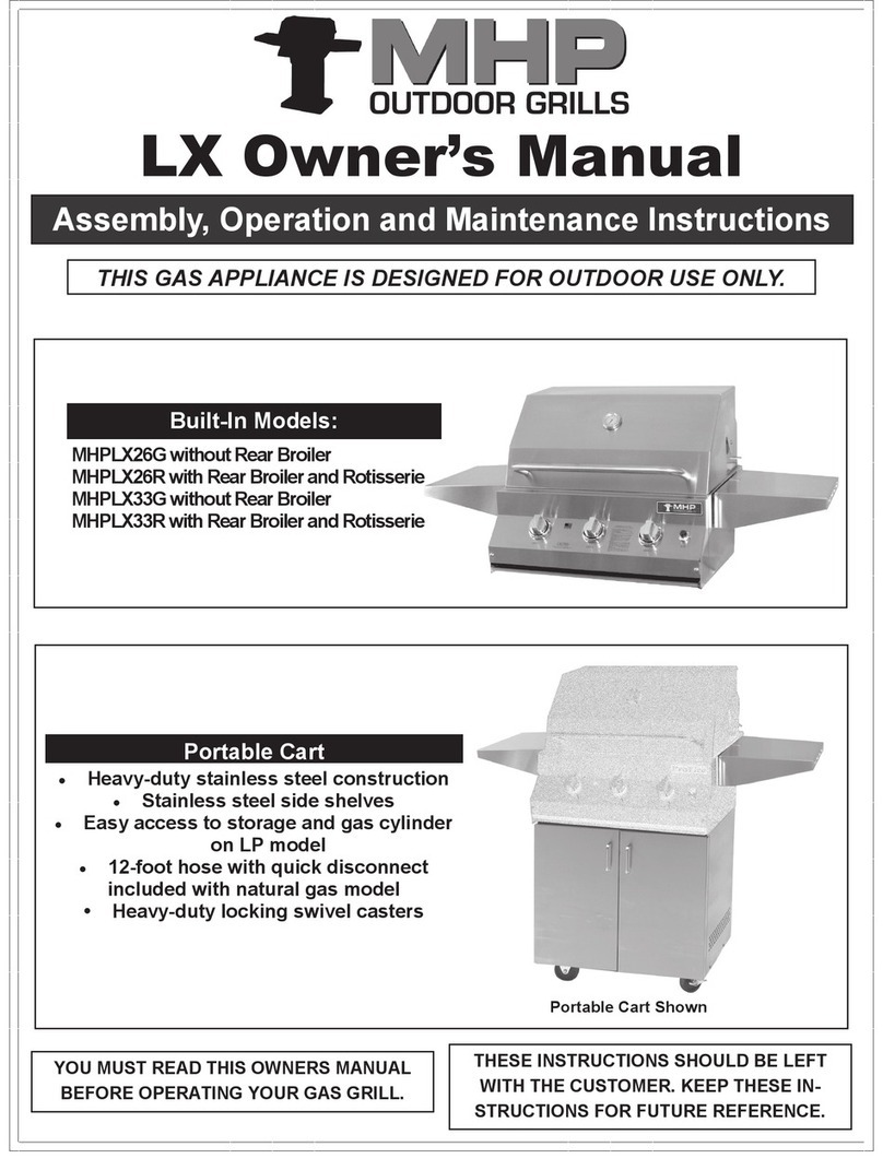
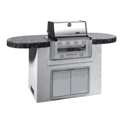
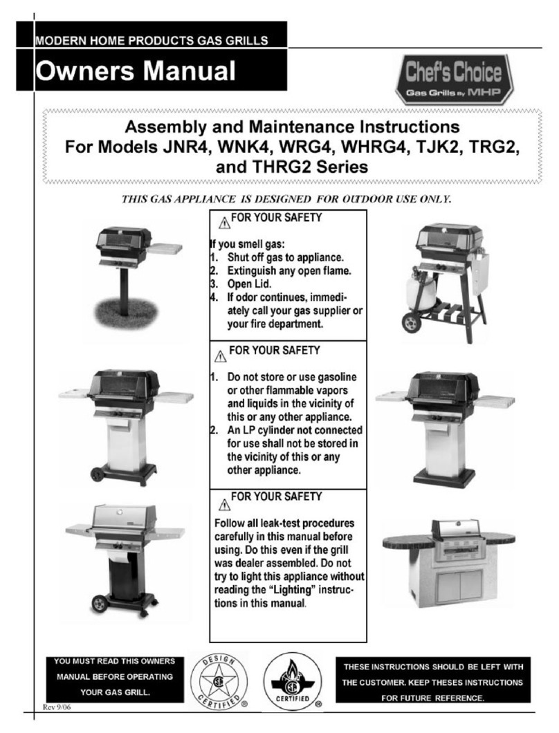
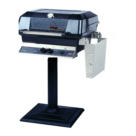
MHP OCOL User manual

www.mhpgrills.com | 1
OCOL
Installation Manual
SCAN THE
QR CODE FOR
ASSEMBLY VIDEO English
OCOLOMN
OCOLOMP
OCOLOPN
OCOLOPP
OCOLOCN
OCOLOCP

2 | www.mhpgrills.com
DANGER: IF YOU SMELL GAS
1. Shut off gas to the appliance
2. Extinguish any open ame
3. Open lid
4. If odor continues, keep away from the
appliance and immediately call your gas
supplier or your re department. Failure to
follow these instructions could result in re or
explosion which could cause property damage,
personal injury or death.
WARNING: FOR YOUR SAFETY
1. Do not store or use gasoline or other ammable
liquids or vapors in the vicinity of this or any other
appliance
2. An LP cylinder not connected for use shall not be
stored in the vicinity of this or any other appliance.
3. Follow all leak-test procedures in your owner’s
manual (included with your grill head) carefully
before using. Do this even if the grill was dealer
assembled. Do not try to light this appliance
without reading the “Lighting” instructions.
The appliance is FOR OUTDOOR USE ONLY. It is not to be used inside a garage, other
building or any type of enclosed area.
WARNING:
• All MHP Grill Heads may be mounted on the column.
• The gas supply may be either LP or Natural
• The grill head should not be attached to the column until the column and base have been completely
PARTS LIST:
IMPORTANT SAFETY WARNINGS
OCOL STAINLESS STEEL COLUMN BOX
TOOLS LIST:
ADJUSTABLE WRENCH 3/4" OPEN END
WRENCH 7/16" OPEN END
WRENCH
GGOTB
TANK LOCK BAR
GGOGC
STAINLESS STEEL
GREASE CUP
GGOCOLR
STAINLESS STEEL
COLUMN
GGAC
STAINLESS STEEL
FRONT ACCESS COVER
HARDWARE KIT
GGM11
STAINLESS STEEL
WASHERS (QTY. 16)
GGOTBS
NYLON TANK BAR
SPACERS (QTY. 2)
GGM4
KEP NUTS
(QTY. 12)
GGM6
1/4 X 20" X 3/4"
HEX BOLTS (QTY. 8)
GGM14
1/4 X 20" X 1-1/4"
HEX BOLTS (QTY. 4)
GGGSKA/GGGSKB
2-PIECE GASKET (1)
LEFT AND RIGHT
7/16" NUT DRIVER RUBBER MALLET

www.mhpgrills.com | 3
Place the stainless steel column facing up. Carefully peel 2 inches of the
thin, white protective lm covering from the top and bottom of the stainless
steel surfaces paying special attention to areas that will be partically hidden
after being assembled. Once assembly is complete you can go back and safely
remove all the of the protective lm.
DO NOT scrape off the lm. This can cause damage to the stainless steel.
Locate the Tank Lock Bar from the OCOL Box
•Align the holes on the bar to the pre-drilled holes on the column.
• Use the 1/4 x 20" x 3/4" Hex Bolt, Nylon Lock Bar Spacer, and a
Kep Nut on each side to fasten the Tank Lock Bar in place. This
spreads and holds the correct spacing at the back of the column.
• Use 7/16" open end wrench to hold the Kep Nut while using
the second open end wrench to tighthen the Bolt.
AFTER CONNECTING THE TANK LOCK BAR YOU CAN ATTACH THE BASE AND THE GAS LINE. FOLLOW THE STEPS FOR YOUR SPECIFIC BASE.
PEELING OFF PROTECTIVE PLASTIC
STEP 1
Choose a location where you are going to set up your grill. Make sure the
surface is at and that there will be enough room to complete the assembly.
CONNECTING THE TANK LOCK BAR
STEP 2
HEX BOLT
NYLON LOCK BAR SPACER
PRE-DRILLED HOLES
KEP NUT
PARTS NEEDED TOOLS NEEDED
GGOTB
TANK LOCK BAR
GGOCOLR
STAINLESS STEEL
COLUMN
HARDWARE NEEDED
GGM6
1/4 X 20" X 3/4"
HEX BOLTS (2)
GGM4
KEP NUTS (2)
7/16" OPEN END GGOTBS
NYLON TANK
BAR SPACERS
OP BASE
Step 3C-OP Page 7-8
Step 3 Page 9
Step 4C-OP Page 12-13
Step 5 Page 14
OM BASE
Step 3B-OM Page 5-6
Step 3 Page 9
Step 4B-OM Page 11
Step 5 Page 14
OC BASE
Step 3A-OC Page 4
Step 3 Page 9
Step 4A-OC Page 10
Step 5 Page 14

4 | www.mhpgrills.com
ATTACH THE BASE TO THE COLUMN (OC BASE)
STEP 3A-OC
PARTS NEEDED FROM OC BOX
OC
CAST ALUMINUM BASE
GGAXL
AXLE
GGGC
AXLE CLIPS (2)
GGWL1
6" WHEELS (2)
OCOL
HUB CAPS (2)
ASPCL1
12' NATURAL
GAS HOSE
(Quick Disconnect)
HARDWARE NEEDEDPART NEEDED (FROM OCOL BOX)
GGM4
KEP NUTS
(QTY. 6)
GGM6
1/4 X 20" X 3/4"
HEX BOLTS (QTY. 6)
GGM11
STAINLESS STEEL
WASHERS (QTY. 12)
TOOLS NEEDED
ADJUSTABLE
WRENCH
7/16" OPEN
END WRENCH
GGGSKA/GGGSKB
2-PIECE GASKET (1)
LEFT AND RIGHT
ATTACH THE GASKET
•Before bolting the column to the base, the
2-piece gasket must be installed to create a
barrier between the two dissimilar metals.
•Remove the backing strips from the gasket to
expose the adhesive and stick the gasket to
the bottom lip of the column. Make sure to
align the holes.
ATTACH THE COLUMN TO THE BASE
•Attaching the column to the base will be easier
to handle by laying the column face down and
matching the holes on the column lip to the holes
on the base.
•Slide a 1/4 x 20" x 3/4" Hex bolt and stainless
steel round washer down to the underside of the
base through the pre-drilled hole on the column
and secure using a Kep Nut.
•Use a 7/16" wrench to hold the Kep Nut while
using a second adjustable wrench to tighten
the bolt. There are a total of six pre-drilled holes
which should be secured.
HEX BOLT
ROUND WASHER
ROUND WASHER
ATTACH WHEELS
• For accessibility, lay the column on it's side.
•Attach the wheels by slipping the axle
through the pre-drilled holes in the
base, slide the wheels onto the axle
and secure with the axle clips.
•Finish by snapping the hub caps on
before standing the unit upright.
AXLE CLIP
AXLE
AXLE
AXLE CLIP
HUBCAP
HUBCAP
HEX BOLT
Included with natural
gas bases only
SCAN THE
QR CODE FOR
ASSEMBLY VIDEO

www.mhpgrills.com | 5
Attach the Column to the Base
•Attaching the column to the base will
be easier to handle by laying the column
face down and matching the holes on
the column lip to the holes on the base.
•Slide a 1/4 x 20" x 3/4" Hex bolt and
stainless steel round washer down to
the underside of the base through the
pre-drilled hole on the column and
secure using a Kep Nut.
•Use a 7/16" wrench to hold the Kep Nut
while using a second adjustable wrench
to tighten the bolt. There are a total
of six pre-drilled holes which should
be secured.
Attach the Gasket
•Before bolting the column to the base, the
2-piece gasket must be installed to create
a barrier between the two dissimilar metals.
•Remove the backing strips from the gasket
to expose the adhesive and stick the gasket
to the bottom lip of the column.
Make sure to align the holes.
HEX BOLT
HEX BOLT
ROUND WASHER
ROUND WASHER
PARTS NEEDED FROM OC BOX
OM
CAST ALUMINUM BASE
GGAXL
AXLE
GGGC
AXLE CLIPS (2)
GGWL
8" WHEELS (2)
OCOL
HUB CAPS (2)
ASPCL1
12' NATURAL
GAS HOSE
(Quick Disconnect)
HARDWARE NEEDED
GGM4
KEP NUTS
(QTY. 6)
GGM6
1/4 X 20" X 3/4"
HEX BOLTS (QTY. 6)
GGM11
STAINLESS STEEL
WASHERS (QTY. 12)
TOOLS NEEDED
ADJUSTABLE
WRENCH
7/16" OPEN
END WRENCH
PART NEEDED (FROM OCOL BOX)
GGGSKA/GGGSKB
2-PIECE GASKET (1)
LEFT AND RIGHT
KKWL
CASTERS (2)
ATTACH THE BASE TO THE COLUMN (OM BASE)
STEP 3B-OM
Included with natural
gas bases only
RUBBER
MALLET
SCAN THE
QR CODE FOR
ASSEMBLY VIDEO

6 | www.mhpgrills.com
ATTACH WHEELS
• For accessibility, lay the column on it's side.
•Attach the wheels by slipping the axle through the pre-drilled holes in
the base, slide the wheels onto the axle and secure with the axle clips.
•Finish by snapping the hub caps on before standing the unit upright.
ATTACH CASTERS
• Place caster stem into stem opening of the portable base.
• Press and tap into place using a rubber mallet, if needed.
STEM OPENING
CASTER
PARTS NEEDED
PARTS NEEDED
OCOL
HUB CAPS (2)
GGAXL
AXLE
GGGC
AXLE CLIPS (2)
GGWL1
8" WHEELS (2)
KKWL
CASTERS (2)
TOOLS NEEDED
ATTACH THE BASE TO THE COLUMN (OM BASE) continued
STEP 3B-OM
RUBBER MALLET
AXLE CLIP
AXLE
AXLE
AXLE CLIP HUBCAP
HUBCAP

www.mhpgrills.com | 7
OP BASE
CAST ALUMINUM BASE
Attach the Gasket
•Before bolting the column to the base, the
2-piece gasket must be installed to create
a barrier between the two dissimilar metals.
•Remove the backing strips from the gasket
to expose the adhesive and stick the gasket
to the bottom lip of the column.
Make sure to align the holes.
Attach the Column to the Base
•Attaching the column to the base will
be easier to handle by laying the column
face down and matching the holes on
the column lip to the holes on the base.
•Slide a 1/4 x 20" x 3/4" Hex bolt and
stainless steel round washer down to
the underside of the base through the
pre-drilled hole on the column and
secure using a Kep Nut.
•Use a 7/16" wrench to hold the Kep Nut
while using a second adjustable wrench
to tighten the bolt. There are a total
of six pre-drilled holes which should
be secured.
HEX BOLT
HEX BOLT
ROUND WASHER
ROUND WASHER
PART NEEDED
3/8" FLARE COUPLING
ADDITIONAL ITEMS NEEDED FOR
PATIO BASE INSTALLATION
(Not Included)
LAG BOLTS (2)
HARDWARE NEEDED
GGM4
KEP NUTS
(QTY. 6)
GGM6
1/4 X 20" X 3/4"
HEX BOLTS (QTY. 6)
GGM11
STAINLESS STEEL
WASHERS (QTY. 12)
TOOLS NEEDED
ADJUSTABLE
WRENCH
7/16" OPEN
END WRENCH
PART NEEDED (FROM OCOL BOX)
GGGSKA/GGGSKB
2-PIECE GASKET (1)
LEFT AND RIGHT
GGCTSS
FLEX TUBE
ATTACH THE BASE TO THE COLUMN (OP BASE)
STEP 3C-OP
Included with
natural gas
bases only
SCAN THE
QR CODE FOR
ASSEMBLY VIDEO

8 | www.mhpgrills.com
The grill head should not be attached to the column until the
base has been permanently mounted to a at and level deck or
patio surface. Not recommended for use on patio pavers.
ATTACH THE BASE TO THE COLUMN (OP BASE) continued
STEP 3B-OP
•Choose a location where you are going to set
up your grill. Make sure the surface is at and
level and be certain that there are no combustible
materials above, behind, left or right closer than
18" away.
•Insert a Lag Bolt into the two pre-drilled holes
located around the center cutout on the OP base.
• Securely tighten lag bolts so that base and column
are stablized.
•Choose a location where you are going to
set up your grill. Make sure the surface is at
and be certain that there are no combustible
materials above, behind, left or right closer than
18" away.
•Run your natural gas line through the notch
located on the back side of the OP base and
continue it up through the center cutout.
Directions for connecting the natural gas line
to the GCTSS exible tubing is outlined in
Step 3B-OP on page 12.
•Insert a Lag Bolt into the two pre-drilled holes
located on the sides of the center cutout of the
OP base.
• Securely tighten lag bolts so that base and
column are stablized.
LAG BOLTS (2)
Not supplied by MHP
Use appropriate
Lag Bolts for
your application
HARDWARE NEEDED
SECURE THE BASE (FOR LP GAS INSTALLATIONS)
SECURE THE BASE (FOR NATURAL GAS INSTALLATIONS)
NOTCH FOR
NATURAL GAS
NATURAL
GAS LINE
CENTER
CUTOUT
LAG BOLT HOLES
LAG BOLT HOLES

www.mhpgrills.com | 9
Attach the Grill Head
• With the column in the upright position,
carefully place the grill head bottom onto
the column aligning the pre-drilled holes
on both the grill bottom and the column.
• Use a 1/4 x 20" x 1-1/4" Hex bolts and
washer through each of four pre-drilled
holes in the bottom of the grill head.
• On the underside of the column lip,
secure each of the Hex bolts with a
Kep Nut. Use a 7/16" nut driver to
hold the Hex Bolt inside the grill while
tightening the Kep Nut on the underside
of the grill head using a 7/16" Open-End
Wrench or Socket Wrench.
Install the Grease Cup
• With the column in the upright
position, locate the grease cup
opening which can be accessed from
the back side of the grill.
•Drop the grease cup into the opening.
• The grease cup should t snuggly
into place.
Remove the Burner (optional)
• Remove the grill burner by taking out the cotter
pins located under the bottom grill head (g. a)
• Pull the burner up and out of the the grill head (g. b).
This will allow access to hold the Kep nuts inside the
post while attaching the bottom casting.
CONNECT THE GRILL HEAD BOTTOM
STEP 4
HEX BOLT
ROUND WASHER
KEP NUT
g. a
g. b
HARDWARE NEEDED
GGM11
STAINLESS STEEL
WASHERS (QTY. 4)
GGOGC
STAINLESS STEEL
GREASE CUP
GGM4
KEP NUTS
(QTY. 4)
GGM14
1/4 X 20" X 1-1/4"
HEX BOLTS (QTY. 4)
TOOLS NEEDED
GGOGC
STAINLESS STEEL
GREASE CUP
GREASE CUP
OPENING
GREASE CUP
BACK OF GRILL
If you are using an OP Base the grill head should not be attached to the column until the base has been permanently
mounted to a deck or patio surface. If this has not been done, see step 3X-OP for steps to secure the OP base.
7/16" NUT DRIVER7/16" OPEN
END WRENCH

10 | www.mhpgrills.com
CONNECTING THE GAS SUPPLY LINE (OC BASE)
STEP 5A-OC
CONNECT THE GAS LINE (FOR LP GAS INSTALLATIONS)
•The LP Hose and Regulator are factory-installed onto
your grill head's LP Valve
•Make sure your gas line runs through the hose
retaining notch opening and continues under
the heat shield as shown in the picture.
•Attach the LP Regulator to your propane tank
and securely hand tighten the coupling nut to
the cylinder valve.
• Before using your grill check for any gas leaks with
a soap and water solution before using your grill.
CONNECT THE GAS LINE (FOR NATURAL GAS INSTALLATIONS)
•Attach the swivel connector end of the ASCPL1 hose
to the gas valve located under the control panel.
•Make sure your gas line runs through the hose
retaining notch opening and continues under the
shelf as shown.
•The socket (quick disconnect) end of the ASCPL1
hose attaches to your gas supply line at your gas
supply line's shut-off valve. Depending on the size of
your gas line you may need a reducer (not supplied
by MHP) to connect your gas line to the quick
disconnect socket (3/8" male pipe thread).
•Tighten all gas connections securely. The use
of two wrenches is recommended—one wrench
is used to hold tting while the other is used
to tighten.
• Before using your grill check for any gas leaks with
a soap and water solution before using your grill.
INCLUDED WITH NATURAL GAS BASES
ASCPL1
12' NATURAL GAS HOSE
(QUICK DISCONNECT)
The swivel connector connects
to the grill's gas valve
The Quick Disconnct
Socket connects to your
gas supply line
The gas supply line must be regulated (in the case of natural gas that means it should be connected after your
gas meter and regulator) and you must have an easily accessible main shut-off valve to your grill’s gas
supply. Grills are designed to operate on a pressure of 7" w.c. in. for Natural or 11"w.c. in for Propane at the
grill valve connection.
When installing a new gas line, it is recommended that you
contact a plumber, heating contractor or licensed gas tter to
install your new gas line to meet local building code. Be certain
there are no combustible materials closer than 18" away (above,
behind, left or right) from your assembled grill.
TOOLS NEEDED
3/4" OPEN END ADJUSTABLE
WRENCH
HEAT SHIELD
GAS HOSE
GAS VALVE
SWIVEL
CONNECTOR
HOSE RETAINING
NOTCH OPENING
GAS SUPPLY
LINE
GAS FLOW
SOCKET PLUG SWIVEL CONNECTOR
HOSE RETAINING
NOTCH OPENING
HEAT SHIELD
QCC-1 Cylinder Valve
Regulator
Coupling Nut
Turn clockwise to connect
Bleed Off Valve
Dust Cover
Pressure
Relief Valve

www.mhpgrills.com | 11
CONNECT THE GAS LINE (FOR LP GAS INSTALLATIONS)
•The LP Hose and Regulator are factory-installed onto
your grill head's LP Valve
•Make sure your gas line runs through the hose
retaining notch opening and continues under
the heat shield as shown in the picture.
•Attach the LP Regulator to your propane tank
and securely hand tighten the coupling nut to
the cylinder valve.
• Before using your grill check for any gas leaks with
a soap and water solution before using your grill.
CONNECT THE GAS LINE (FOR NATURAL GAS INSTALLATIONS)
The gas supply line must be regulated (in the case of natural gas that means it should be connected after your
gas meter and regulator) and you must have an easily accessible main shut-off valve to your grill’s gas
supply. Grills are designed to operate on a pressure of 7" w.c. in. for Natural or 11"w.c. in for Propane at the
grill valve connection.
When installing a new gas line, it is recommended that you
contact a plumber, heating contractor or licensed gas tter to
install your new gas line to meet local building code. Be certain
there are no combustible materials closer than 18" away (above,
behind, left or right) from your assembled grill.
TOOLS NEEDED
3/4" OPEN END ADJUSTABLE
WRENCH
•Attach the swivel connector end of the ASPCL1 hose
to the gas valve located under the control panel.
•Make sure your gas line runs through the hose
retaining notch opening and continues under the
shelf as shown.
•The socket (quick disconnect) end of the ASPCL1
hose attaches to your gas supply line at your gas
supply line's shut-off valve. Depending on the size of
your gas line you may need a reducer (not supplied
by MHP) to connect your gas line to the quick
disconnect socket (3/8" male pipe thread).
•Tighten all gas connections securely. The use of two
wrenches is recommended—one wrench is used to
hold tting while the other is used to tighten.
• Before using your grill check for any gas leaks with
a soap and water solution before using your grill.
CONNECTING THE GAS SUPPLY LINE (OM BASE)
STEP 5B-OM
INCLUDED WITH NATURAL GAS BASES
ASCPL1
12' NATURAL GAS HOSE
(QUICK DISCONNECT)
The swivel connector connects
to the grill's gas valve
The Quick Disconnct
Socket connects to your
gas supply line
HEAT SHIELD
GAS HOSE
GAS VALVE
SWIVEL
CONNECTOR
HOSE RETAINING
NOTCH OPENING
GAS SUPPLY
LINE
GAS FLOW
SOCKET PLUG SWIVEL CONNECTOR
HOSE RETAINING
NOTCH OPENING
HEAT SHIELD
QCC-1 Cylinder Valve
Regulator
Coupling Nut
Turn clockwise to connect
Bleed Off Valve
Dust Cover
Pressure
Relief Valve

12 | www.mhpgrills.com
CONNECT THE GAS LINE (FOR LP GAS INSTALLATIONS)
•The LP Hose and Regulator are factory-installed onto your grill head's LP Valve
•
Attach the LP Regulator to your propane tank and securely hand tighten the coupling nut to the cylinder valve.
• Before using your gril check for any gas leaks with a soap and water solution before using your grill.
CONNECTING THE GAS SUPPLY LINE (OP BASE)
STEP 5C-OP
HEAT SHIELD
LP GAS HOSE
HOSE RETAINING
NOTCH OPENING
QCC-1 Cylinder Valve
Regulator
Coupling Nut
Turn clockwise to connect
Bleed Off Valve
Dust Cover
Pressure
Relief Valve

www.mhpgrills.com | 13
The gas supply line must be regulated (in the case of
natural gas that means it should be connected after your
gas meter and regulator) and you must have an easily
accessible main shut-off valve to your grill’s gas
supply. Grills are designed to operate on a pressure
of 7" w.c. in. for Natural or 11"w.c. in for Propane at the
grill valve connection.
When installing a new gas line, it is recommended that you contact a plumber, heating contractor
or licensed gas tter to install your new gas line to meet local building code. Be certain there are no
combustible materials closer than 18" away (above, behind, left or right) from your assembled grill.
Attach Natural Gas Line to the GGCTSS Flex Tube
• Connect a 3/8" are coupling (not supplied by MHP) to the
gas supply line then the exible stainless-steel tubing
(GGCTSS) using a 3/4" wrench. The use of two wrenches is
recommended—one wrench is used to hold tting while the
other is used to tighten.
Tighten very securely as are ttings are
a metal-upon-metal surface seal and no
additional gas sealant is needed.
GGCTSS
GAS
SUPPLY
LINE
CONNECT THE GAS LINE (FOR NATURAL GAS INSTALLATIONS)
3/8" FLARE
COUPLING
(Not supplied
by MHP)
CONNECTING THE GAS SUPPLY LINE (OP BASE) continued
STEP 5C-OP
Attach the GGCTSS Flex Tube to the
Gas Valve
•Attach the swivel connector end of
the GGCTSS Flex Tube to the gas
valve located under the control panel.
•Make sure your gas line runs through
the hose retaining notch opening and
continues under the shelf as shown.
•Tighten all gas connections
securely. The use of two wrenches
is recommended—one wrench is
used to hold tting while the other
is used to tighten.
• Before using your grill check for
any gas leaks with a soap and water
solution before using your grill. HEAT SHIELDGGCTSS
FLEX TUBE
GAS VALVESWIVEL
CONNECTOR
HOSE RETAINING
NOTCH OPENING
TOOLS NEEDED
3/4" OPEN END
ADJUSTABLE
WRENCH
PARTS NEEDED
GGCTSS
FLEX TUBE
3/8" FLARE COUPLING
(Not supplied by MHP)

14 | www.mhpgrills.com
Attach the Access Panel Cover
•The front access panel cover attaches directly under the control panel and hides
the access opening.
• Lift the access panel up behind the lip of the control panel (g. a).
• Slip the bottom double edge of the access panel cover over the edge of the access
opening (upward pressure may be needed) (g. b).
ATTACHING THE ACCESS PANEL
STEP 6
Do not attach the front access panel until the control panel has been attached to the grill head
bottom and the gas supply line has been properly connected and leak tested.
g. a
g. b
GGAC
STAINLESS STEEL
FRONT ACCESS COVER

www.mhpgrills.com | 15
=
Enhance Your Grill
Our premium accessories have been designed specically for our grills
with quality materials and craftsmanship
Visit your local dealer or our online store
www.mhponlinestore.com
Clean and Maintain Your Grill
Keep your grill running smoothly with these accessories
designed specifically to work with your MHP Grill.
BEER CAN CHICKEN ROASTER
Grill up a tender but juicy whole
chicken infused wth your favorite
beer, wine , juice or marinade.
beverage can easily t in the can
support ring.
Nickel-plated and dishwasher-safe.
CCR
STAINLESS STEEL SPATULA
This heavy-duty stainless steel
spatula is specially curved for perfect
ips everytime. Features a solid wood
grip handle and a sturdy stainless
steel hanger ring for easy storage.
18" long (end-to-end).
SF1
STAINLESS STEEL SMOKER BOX
Easily add authentic wood smoke
avor to your food with this smoker
box designed to work with all MHP
Grills. Insert moistened wood chips
(not included) for your favorite smoke
avor. Stainless steel construction
with a removable vented lid.
SSST
Brass Bristle SearMagic
Cooking Grid Brush
GGWB10
21" Stainless Steel Handle
Brass Bristle Brush
WB8
Replacement Brass
Bristle Brush Head
WB8RH
Stainless Steel
Grill Cleaner
SCC
SAUSAGE STUFFED JALAPEÑO PEPPERS
(makes 12 stuffed peppers)
Instructions:
• Cut top off jalapeno peppers, remove the seeds
& membranes
• Brown sausage in a skillet
• Mix cream cheese, Parmesan cheese, and sausage
• Stuff jalapeños with combined cheese & sausage
mixture then replace jalapeno caps
• Place stuffed pepper in your jalapeño pepper tray
Preheat your grill to 350° and grill for 30 minutes. During this time the spicy heat will be cooked
from the pepper and you can enjoy your jalapenos.
Ingredients:
• 12 Jalapeño Peppers
• 1/2 pound cooked bulk pork sausage
• 4 oz cream cheese
• 1/2 cup shredded Parmesan cheese
• Serve with y our favorite prepared
ranch dressing (optional)
JALAPEÑO PEPPER TRAY
Holds up to 24 jalapeño peppers.
Stainless steel. American made.
JPT

16 | www.mhpgrills.com © MHP 2020, All Rights Reserved
Family Owned & Operated Since 1957 AM-OCOL-0222
California Proposition 65 Warning: This product can expose you to chemicals including Chromium (hexavalent compounds),
which are known to the State of California to cause cancer and birth defects or other reproductive harm. For more
information go to: www.P65Warnings.ca.gov.
TECHNICAL SUPPORT
Modern Home Products
150 South Ram Road • Antioch, IL 60002
847.395.6556 • 888.647.4745
[email protected] • www.mhpgrills.com
Make the most out of your grilling experience!
From side burners and rotisseries to grill covers and more—
we carry a complete line of grill upgrades, accessories and grill parts
designed specically for your MHP Grill.
rVisit MHPGrills.com for more information
This manual suits for next models
6
Table of contents
Other MHP Grill manuals
Popular Grill manuals by other brands

Sunco
Sunco SC90-12 Assembly & operating manual
oneConcept
oneConcept 10028047 quick start guide

German pool
German pool KQB-12 user manual
Members Mark
Members Mark CG2036001-MM owner's manual

FCC BBQ
FCC BBQ Tjome large FCC-PG-19510 Instructions, manual, maintenance

Silvercrest
Silvercrest 306420 operating instructions
essentiel b
essentiel b EBGZ 6 user guide

Silvercrest
Silvercrest 379075 2110 operating instructions
MasterChef
MasterChef TF2201804-MC user manual

Silvercrest
Silvercrest STGG 1800 A1 operating instructions
GGM gastro
GGM gastro HKGK13 Installation and operation manual

MasterChef
MasterChef PRIME 85-3135-0 Assembly manual
