MHSC BLOTKSTSC User manual

Blower
Installation Instructions
Model: BLOTKSTSC
For Signature Command Systems
Before You Start
The BLOTKSTSC Blower Kit is designed to be installed with the Signature Command System with
the SCSACM A/C control module and is controlled only with the RFSC remote control.
NOTE: This instruction sheet is ONLY for models listed below. Carefully inspect the contents for
shipping damage. If any parts are missing or damaged, immediately inform the dealer from whom
you purchased the part.
Models: KSTDV/DVKST
NOTE: This kit contains only one blower, however, two (2) blowers may be installed if desired as
shown in Figure 2. An additional BLOTKSTSC blower kit must be purchased.
Kit Contents:
1, Blower 1, Louvered Access Panel, Right
1, Wire Harness 1, Louvered Access Panel, Left
4, #8 Sheet Metal Screws
Tools Required:
Short handle Phillips screwdriver
WARNING
Before installing the blower, turn off the fireplace
and allow to cool. Only a qualified service person
should service and repair the fireplace. A qualified
service person should connect and disconnect the
fireplace to gas supply. Follow all local codes.
WARNING
Electrical Grounding Instructions:
This appliance is equipped with a three-prong
(grounding) plug for your protection against shock
hazard and should be plugged directly into a prop-
erly grounded three prong receptacle.
CAUTION
Electrical connections should only be performed
by a qualified licensed electrician. Main power
supply must be turned off before connecting fans
to the main electrical power supply or performing
service.
IMPORTANT: Always check local building codes. This
installation must comply with local regulations as well
as the National Electric Code.
Installation Instructions
Wiring
1. Before installing the blower, wire the receptacle into an electrical
circuit. This should be done before framing the fireplace. Wire with
minimum 60° C wire in accordance with prevailing codes.
2. Remove the external junction box cover by removing the screw
from the left side of the outside firebox wall. Junction box was
installed at the factory.
3. The junction box cover has a factory installed “romex” style strain
relief connector. After connecting the wires, route the wire leads
through this connector. Refer to the wiring diagram in Figure 5.
73D4166 11/09 Rev. 1
FP1912
Junction box wiring
8/08
Junction Box
120V AC
60Hz
Factory Supplied
Not Supplied
Figure 1
Junction Box Wiring Diagram
273D4166
Installing the Blower
1. Remove the plate located in front of the glass at the bot-
tom.
2. Remove rod provided for screen assembly located
beneath the cover plate.
3. Rotate the access doors on the right and left side of the
glass toward the glass.
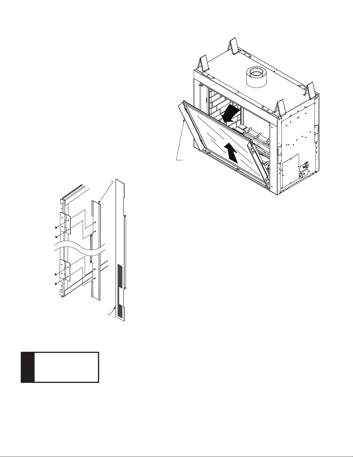
4. Remove glass frame by releasing the three latches located
at the top of the firebox. Tilt glass away from the unit, lift
glass frame up and away from the unit. Figure 2
5. Replace side panels attached to the glass frame as-
sembly with the louvered side panels provided with
the blower kit by unfastening the four nuts for each
cover door. (Do not overtighten or stud may break
off.) Use three metal clip screws provided with kit to
secure the wire assembly in the front beneath the
access cover. Figure 3
NOTE
Keep wires away from
combustion chamber
and blower wheel.
FP2549
glass frame removal
Figure 2 -
Remove Glass Frame
Glass
Frame
FP2549
Figure 3 -
Install New Louvers
FP2234
install louvers
1/09
Remove Solid
Access Door
Replace with Louvered Access
Door, Louvers Towards Bottom
FP2234
6. Remove the four (4) screws securing the light box on control
side of unit.
7. Remove brick wall panel from firebox wall.
8. Remove blower access panel from firebox wall. Figure 4
9. Disassemble blower mounting bracket from blower access
panel. Figure 5. Mount blower to mounting bracket with the
supplied #8 sheet metal screws. The blower may be mounted
on either side of unit according to where the owner would
like the discharge to be.
10. Wiring for one (1) blower: Attach the two (2) female con-
nectors from A/C Module marked ‘Blower’ to the two (2) male
connectors on blower. Figure 6. Wire clip on blower mounting
bracket can be used to route wires away from blower blades.
NOTE: Discard wire harness for one blower installation.
Wiring for two (2) blowers: There is one (1) wire harness
supplied with each blower kit. Attach the two (2) female con-
nectors from one wiring harness to one (1) male connector on
each blower. Repeat with the second wiring harness. Attach
the two (2) male connectors from the wiring harness to the
female connectors from the A/C Module marked ‘Blower’.
Figure 7
11. Reassemble blower access panel with blower(s) installed
into firebox.
12. Replace brick wall panel.
13. Replace glass frame.

73D4166 3
KT1194
blower access plate
Blower
Access
Plate
KT1194
Figure 4
KT1195
install blower
Access Plate
Access Plate
Gasket
To
Blower
To Blower
To A/C Box
Blowers
KT1195
Figure 5
F
M
F
M
KT1201
wiring one blower
Blower
To A/C
Module
KT1201
Figure 6 -
Wiring for One Blower

473D4166
M
FF
F
F
F
F
M
M
M
M
M
KT1202
wiring two blowers
Wire Harness Sup-
plied in Blower Kit To A/C
Module
Blowers
Figure 7 -
Wiring for Two Blowers
KT1202
MHSC
149 Cleveland Drive • Paris, Kentucky 40361
www.mhsc.com
To Junction Box
In Fireplace
White
Black
White
Black Black
White
Green
Connector
Pin To Control Box
AC Module
{
{
Light
Rear
Burner
Solenoid
Control Box
Blower
Right
Blower
Left
Black
Black
FP1915
AC box wiring
8/08
Figure 8 -
Blower Wiring Diagram
FP1915


