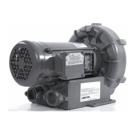
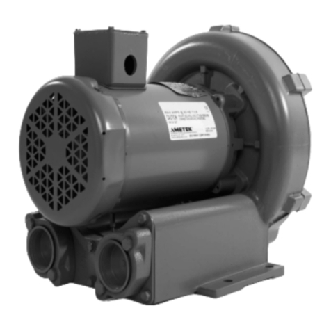
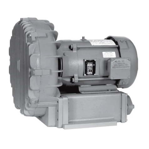
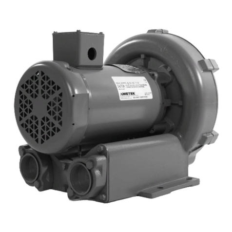
Ametek EN858 Building instructions

Your Choice. Our Commitment.
SERVICE AND PARTS MANUAL
FOR
BLOWER MODEL
EN6, EN858, EN909, EN979, EN14
DIRECT DRIVE REGENERATIVE
BLOWER
Technical & Industrial Products
627 Lake Street, Kent, Ohio 44240 U.S.A.
Telephone: 330-673-3452 Fax: 330-677-3306
internet:
www.ametektip.com

1 Revised – February 2005
W A R R A N T Y , I N S T A L L A T I O N , M A I N T E N A N C E A N D
T R O U B L E S H O O T I N G I N S T R U C T I O N S
TECHNICAL AND INDUSTRIAL PRODUCTS
627 Lake Street, Kent, Ohio 44240 USA
Telephone: 330-673-3452 Fax: 330-677-3306
www.ametektip.com
1. AMETEK Rotron DR, EN and HiE regenerative direct drive blowers are guaranteed for one full
year from the date of installation (limited to 18 months from the date of shipment) to the original
purchaser only. Should the blower fail we will evaluate the failure If failure is determined to be
workmanship or material defect related, we will at our option repair or replace the blower.
2. AMETEK Rotron Minispiral, Revaflow, Multiflow, Nautilair, remote drive blowers, moisture
separators, packaged units, CP blowers, Nasty Gas™ models and special built (EO) products are
guaranteed for one full year from date of shipment for workmanship and material defect to the
original purchaser only. Should the blower fail, If failure is determined to be workmanship or
material defect related, we will at our option repair or replace the blower.
3. Parts Policy - AMETEK Rotron spare parts and accessories are guaranteed for three months from
date of shipment for workmanship and material defect to the original purchaser only. If failure is
determined to be workmanship or material defect related we will at our option repair or replace the
part.
Corrective Action - A written report will be provided indicating reason(s) for failure, with suggestions
for corrective action. Subsequent customer failures due to abuse, misuse, misapplication or repeat
offense will not be covered. AMETEK Rotron will then notify you of your options. Any failed unit that is
tampered with by attempting repair or diagnosis will void the warranty, unless authorized by the
factory.
Terms and Conditions - Our warranty covers repairs or replacement of regenerative blowers only,
and will not cover labor for installation, outbound and inbound shipping costs, accessories or other
items not considered integral blower parts. Charges may be incurred on products returned for reasons
other than failures covered by their appropriate warranty. Out-of-warranty product and in warranty
product returned for failures determined to be caused by abuse, misuse, or repeat offense will be
subject to an evaluation charge. Maximum liability will in no case exceed the value of the product
purchased. Damage resulting from mishandling during shipment is not covered by this warranty. It is
the responsibility of the purchaser to file claims with the carrier. Other terms and conditions of sale are
stated on the back of the order acknowledgement.
Installation Instructions for SL, DR, EN, CP, and HiE Series Blowers
1. Bolt It Down - Any blower must be secured against movement prior to starting or testing to
prevent injury or damage. The blower does not vibrate much more than a standard electric motor.
2. Filtration - All blowers should be filtered prior to starting. Care must be taken so that no foreign
material enters the blower. If foreign material does enter the blower, it could cause internal
damage or may exit at extremely high velocity.
Should excessive amounts of material pass through the blower, it is suggested that the cover(s)
and impeller(s) be removed periodically and cleaned to avoid impeller imbalance. Impeller

2 Revised – February 2005
imbalance greatly speeds bearing wear, thus reducing blower life. Disassembling the blower will
void warranty, so contact the factory for cleaning authorization.
3. Support the Piping - The blower flanges and nozzles are designed as connection points only and
are not designed to be support members.
Caution: Plastic piping should not be used on blowers larger than 1 HP that are operating near
their maximum pressure or suction point. Blower housing and nearby piping
temperatures can exceed 200ºF. Access by personnel to the blower or nearby piping
should be limited, guarded, or marked, to prevent danger of burns.
4. Wiring - Blowers must be wired and protected/fused in accordance with local and national
electrical codes. All blowers must be grounded to prevent electrical shock. Slo-Blo or time delay
fuses should be used to bypass the first second of start-up amperage.
5. Pressure/Suction Maximums - The maximum pressure and/or suction listed on the model label
should not be exceeded. This can be monitored by means of a pressure or suction gage (available
from Rotron), installed in the piping at the blower outlet or inlet. Also, if problems do arise, the
Rotron Field representative will need to know the operating pressure/suction to properly diagnose
the problem.
6. Excess Air - Bleed excess air off. DO NOT throttle to reduce flow. When bleeding off excess air,
the blower draws less power and runs cooler.
Note: Remote Drive (Motorless) Blowers - Properly designed and installed guards should be used
on all belts, pulleys, couplings, etc. Observe maximum remote drive speed allowable. Due to the
range of uses, drive guards are the responsibility of the customer or user. Belts should be
tensioned using belt gauge.
Maintenance Procedure
When properly piped, filtered, and applied, little or no routine maintenance is required. Keep
the filter clean. Also, all standard models in the DR, EN, CP, and HiE series have sealed
bearings that require no maintenance. Bearing should be changed after 15,000 to 20,000
hours, on average. Replacement bearing information is specified on the chart below.
Bearing
Part Number Size Seal Material Grease Heat Stabilized
510217
510218
510219
205
206
207 Polyacrylic
Nye Rheotemp 500
30% +/- 5% Fill Yes – 325 F
510449
516440
516648
203
202
307
Buna N Exxon Polyrex Grease NO
516840
516841
516842
516843
516844
516845
516846
516847
206
207
208
210
309
310
311
313
Buna N Exxon Polyrex Grease NO

3 Revised – February 2005
Troubleshooting
POSSIBLE CAUSE OUT OF WARRANTY REMEDY ***
IMPELLER DOES NOT
TURN
Humming Sound
1. * One phase of power line not connected
2. * One phase of stator winding open
3. Bearings defective
4. Impeller jammed by foreign material
5. Impeller jammed against housing or cover
6. ** Capacitor open
1. Connect
2. Rewind or buy new motor
3. Change bearings
4. Clean and add filter
5. Adjust
6. Change capacitor
No
Soun
d
1. * Two phases of power line not connected
2. * Two phases of stator winding open 1. Connect
2. Rewind or buy new motor
IMPELLER TURNS
Blown
Fuse
1. Insufficient fuse capacity
2. Short circuit 1. Use time delay fuse of proper
rating
2. Repair
Motor Overheated Or
Protector Trips
1. High or low voltage
2. * Operating in single phase condition
3. Bearings defective
4. Impeller rubbing against housing or cover
5. Impeller or air passage clogged by foreign material
6. Unit operating beyond performance range
7. Capacitor shorted
8. * One phase of stator winding short circuited
1. Check input voltage
2. Check connections
3. Check bearings
4. Adjust
5. Clean and add filter
6. Reduce system pressure/vacuum
7. Change capacitor
8. Rewind or buy new motor
Abnormal
Sound
1. Impeller rubbing against housing or cover
2. Impeller or air passages clogged by foreign
material
3. Bearings defective
1. Adjust
2. Clean and add filter
3. Change bearings
Performance
Below Standard
1. Leak in piping
2. Piping and air passages clogged
3. Impeller rotation reversed
4. Leak in blower
5. Low voltage
1. Tighten
2. Clean
3. Check wiring
4. Tighten cover, flange
5. Check input voltage
* 3 phase units
** 1 phase units
*** Disassembly and repair of new blowers or motors will void the Rotron warranty. Factory should be contacted
prior to any attempt to field repair an in-warranty unit.
Blower Disassembly:
WARNING: Attempting to repair or diagnose a blower may void Rotron’s warranty. It may also
be difficult to successfully disassemble and reassemble the unit.
1) Disconnect the power leads. CAUTION: Be sure the power is disconnected before doing any work
whatsoever on the unit.
2) Remove or separate piping and/or mufflers and filters from the unit.
3) Remove the cover bolts and then the cover. NOTE: Some units are equipped with seals. It is
mandatory that these seals be replaced once the unit has been opened.
4) Remove the impeller bolt and washers and then remove the impeller. NOTE: Never pry on the
edges of the impeller. Use a puller as necessary.
5) Carefully note the number and location of the shims. Remove and set them aside. NOTE: If the
disassembly was for inspection and cleaning the unit may now be reassembled by reversing the
above steps. If motor servicing or replacement and/or impeller replacement is required the same
shims may not be used. It will be necessary to re-shim the impeller according to the procedure
explained under assembly.

4 Revised – February 2005
6) Remove the housing bolts and remove the motor assembly (arbor/.housing on remote drive
models).
7) Arbor disassembly (Applicable on remote drive models only):
a) Slide the bearing retraining sleeve off the shaft at the blower end.
b) Remove the four (4) screws and the bearing retaining plate from the blower end.
c) Lift the shaft assembly far enough out of the arbor to allow removal of the blower end snap
ring.
d) Remove the shaft assembly from the arbor.
e) If necessary, remove the shaft dust seal from the pulley end of the arbor.
Muffler Material Replacement:
1) Remove the manifold cover bolts and them manifold cover.
2) The muffler material can now be removed and replaced if necessary. On blowers with fiberglass
acoustical wrap the tubular retaining screens with the fiberglass matting before sliding the muffler
pads over the screens.
3) Reassemble by reversing the procedure.
NOTE: On DR068 models with tubular mufflers it is necessary to remove the cover and
impeller accessing the muffler material from the housing cavity.
Blower Reassembly:
1) Place the assembled motor (assembled arbor assembly for remote drive models) against the rear
of the housing and fasten with the bolts and washer.
2) To ensure the impeller is centered within the housing cavity re-shim the impeller according to the
procedure outlined below.
3) If blower had a seal replace the seal with a new one.
4) Place the impeller onto the shaft making sure the shaft key is in place and fasten with the bolt,
washer and spacer as applicable. Torque the impeller bolt per the table below. Once fastened
carefully rotate the impeller to be sure it turns freely.
5) Replace the cover and fasten with bolts.
6) Reconnect the power leads to the motor per the motor nameplate.
Bolt Size Torque
Pound-Force-Foot
1/4-20 6.25 +/- 0.25
5/16-18 11.5 +/- 0.25
3/8-16 20.0 +/- 0.5
½-13 49.0 +/- 1
5/8 –11 90.0 +/- 2

5 Revised – February 2005
Impeller Shimming Procedure:
WARNING: This unit may be difficult to shim. Extreme care may be exercised.
Tools Needed:Machinist’s Parallel Bar
Vernier Caliper with depth measuring capability
Feeler gauges or depth gauge
Measure the Following:
Distance from the flange face to the housing (A)
Distance from the flange face to the motor shaft shoulder (B)
Impeller Thickness (C)
Measurements (A) and (B) are made by laying the parallel bar across the housing flange face and
measuring to the proper points. Each measurement should be made at three points, and the average
of the readings should be used.
Shim Thickness = B – (A+C)/2
After the impeller installation (step #4 above) the impeller/cover clearance can be checked with feeler
gauges, laying the parallel bar across the housing flange face. This clearance should nominally be
(A-C)/2.
C
BA

7
H. 1
∅
∅∅
∅
, 6 WIRE
115 VAC 230 VAC
1
1
LINE
3
LINE
2
5
3
2
5
4
LINE
4
LINE
8
8
INTERCHANGE LEADWIRES 5 & 8 to REVERSE ROTATION
I. 1
∅
∅∅
∅
, 7 WIRE
115 VAC 230 VAC
1
LINE 1 LINE
3
2
2 3
4 LINE
4
8 LINE
8
5
5
9
9
INTERCHANGE LEADWIRES 5 & 8 to REVERSE ROTATION
K. 3
∅
∅∅
∅
, 9 WIRE
230 VAC 460 VAC
LINE
1 LINE 1
LINE
7 2
LINE
3
2 LINE
8 4
7
3 LINE
9 5
8
4
5 6
6 9
INTERCHANGE ANY TWO LEAD LINES TO REVERSE ROTATION
M. 1
∅
∅∅
∅
230 VAC
SINGLE VOLTAGE
1
LINE
5
4
LINE
8
INTERCHANGE LEADWIRES 5 & 8 TO REVERSE ROTATION
WIRING DIAGRAMS, XP MOTORS
L. PILOT DUTY THERMAL OVERLOADS
J
J
HOOK J LEADS TO CONTROL CIRCUITRY
N. 3
∅
∅∅
∅
575 VAC
1
LINE
2
LINE
3
LINE
INTERCHAGE ANY TWO LEAD LINES TO REVERSE ROTATION

P 3
∅
∅∅
∅
, 9 WIRE
230 VAC 460 VAC
1 1 Line
6 Line 2 Line
7 3 Line
2 4
4 Line 7
8 5
8
3
6
5 Line
9
9
INTERCHANGE ANY TWO LEAD LINES TO REVERSE ROTATION

02/20/02 Rev. E
ROTRON TECHNICAL MOTOR DIVISION
REGENERATIVE BLOWER GROUP
75 North Street
Saugerties, New York 12477
Phone: (845) 246-3401
Fax: (845) 246-3802
IMPORTANT: Read before wiring this Explosion-proof Blower
This AMETEK Rotron Explosion-proof Regenerative Blower may be equipped with Pilot Duty
Thermal Overload (PDTO) or Automatic Thermal Overload (ATO) protection. When properly
wired to a motor starter, this protection limits the motor winding temperature rise per the
National Electric Code (NEC) article 500. Failure to properly wire this blower is an NEC
violation and could cause an explosion. AMETEK Rotron assumes no responsibilities for
damages incurred by negligent use of this product, and will not warranty a blower on which the
PDTO is not properly connected. Some blowers 1 HP and under do not require PDTO and
have built in ATO. Consult the factory if verification of wiring connections is required.
In all cases, follow the motor controller manufacturer’s instructions. The following schematic is
for conceptual understanding only, and may not apply to all motor/controller combinations.
The manufacturer’s wiring diagram found on the motor takes precedent over reference
diagrams supplied by AMETEK Rotron Technical Motor Division.
The schematic is shown for a
three phase motor. For a
single phase motor disregard
L3 and M3. Pushing the
START button completes the
auxiliary control circuit,
allowing current to flow
through the magnetic coil.
The contacts are
magnetically closed, starting
the motor and latching the
auxiliary circuit. The motor
will continue to run until the
STOP push button is
depressed, the motor
reaches the overload
temperature, or the current
sensing overloads trip out.
If you have any questions, contact AMETEK Rotron at 914-246-3401 for the location of your
area representative.
EXPLOSION
-
PROOF BLOWERS
A1
A2
L1
L2
L3
Push Start
Push Stop
Magnetic Coil
Current
Overloads
Contacts
Auxiliary
Power
J
M1
M2
M3
J
J – Pilot Duty Thermal Overload Protection wires
L – Power leads from circuit breaker box
M – Motor leads (refer to wiring diagram inside T’box or on motor nameplate)
Motor
Schematic

02/20/02 Rev. E
P
OLICY
R
EGARDING
I
NSTALLATION OF
AMETEK
R
OTRON
R
EGENERATIVE
B
LOWERS IN
H
AZARDOUS
L
OCATIONS
AMETEK Rotron will not knowingly specify, design or build any regenerative blower for
installation in a hazardous, explosive location without the proper NEMA motor enclosure.
AMETEK Rotron does not recognize sealed blowers as a substitute for explosion-proof
motors. Sealed units with standard TEFC motors should never be utilized where local, state,
and/or federal codes specify the use of explosion-proof equipment.
AMETEK Rotron has a complete line of regenerative blowers with explosion-proof motors.
Division 1 & 2, Class I, Group D; Class II, Groups F & G requirements are met with these
standard explosion-proof blowers.
AMETEK Rotron will not knowingly specify, design or build any regenerative blower for
installation in a hazardous, corrosive environment without the proper surface treatment and
sealing options.
AMETEK Rotron has a complete line of Chemical Processing and Nasty Gas™ regenerative
blowers with Chem-Tough™, stainless steel parts, and seals.
AMETEK Rotron offers general application guidance; however, suitability of the particular
blower selection is ultimately the responsibility of the purchaser, not the manufacturer of the
blower.
FS2 Rev. B 3/10/98

ASSEMBLY DIAGRAM
EN6 EN808 EN909 EN14

13
14
21
3
4
5
6
7
10
11
12
9
16
32
33
34
IN
OUT
17
19
20
18
8
272829
31
30
242526
23
256TEFC
19.85longx4.6ODTUBE
ASSEMBLYDIAGRAM"B"

EN 6/858/909/14
Service and Parts Manual
Model: EN6 EN858 EN909 EN909 EN14 EN14 EN979
Part No.: 038361 038744 038629 081741 038762 038760 80724
038180 038745 038634 081736 038761
038438 080070 080071 081743
Item
No.
Qty.
Req'd OBSOLETE
M3 1 510212 511532 511532 511532 155066 511532 551570
B1 6 (4 pcs) 120065 (4 pcs) 155067 140016 140016 140016 140016 140016
B2 Not Used Not Used Not Used Not Used Not Used Not Used Not Used
B3 2 See Next Page 511614 529912 529912 529912 529912 529912
2 Not Used Not Used 155377 155377 155377 155377 155377
See Next Page Not Used Not Used Not Used Not Used Not Used Not Used
B4 1 516747 516764 515356 552409 516799 516797 551560
B5 4 251792 155034 140014 see below 120205 120205 120205
B6 7 Not Used 551736 (10 pcs) 551738
(2 pcs) 552477 (12)551740 (12)551740
(8) 551571
2 Not Used 551737 551739 552483 551741 551741 Not Used
2 Not Used Not Used 551730 Not Used 551744 551744 Not Used
B8 * 272703 511547 511547 511547 515991 511547 511547
* 272704 511548 511548 511548 515992 511548 511548
* 272705 511549 511549 511549 515993 511549 511549
* 272706 511550 511550 511550 515994 511550 511550
* Not Used Not Used Not Used Not Used Not Used Not Used Not Used
B9 1 515484 515249 552544 552431 515509 515683 551566
B10 1 251791 120210 140015 140015 155068 120251 140015
B11 1 251787 251788 251788 251788 251788 251788 251788
B12 1 Not Used 511529 Not Used Not Used Not Used Not Used Not Used
B13 1 515488 515247 515359 515359 515910 515910 551409
B14 8 155170 140016 140016 140016 155069 155069 155512
B15 1 Not Used 140019 140019 Not Used 140019 140019 Not Used
B16 1 478336 515555 511529 511529 515990 515990 511529
Not Used Not Used Not Used Not Used Not Used Not Used Not Used
B17 Not Used Not Used Not Used Not Used Not Used Not Used Not Used
B18 2 Not Used 551723 551725 552479 551727 551727 551611
B19 6 Not Used 155025 155025 (4 pcs) 155025 155067 155067 155512
B19A 4Not Used 120214 120214 120210 120214 120214 Not Used
B20 1 Not Used 550019 529932 552428 550039 550039 551422
1 522948 Not Used Not Used Not Used Not Used Not Used Not Used
Not Used Not Used Not Used Not Used Not Used Not Used Not Used
B21 Not Used Not Used Not Used Not Used Not Used Not Used Not Used
B22
Not Used Not Used Not Used Not Used Not Used Not Used Not Used
B23 4
251791 120007 140016 120205 120256 155025 120256
B24 4
251787 251787 251787 251787 251788 251788 Not Used
B24A 8
Not Used Not Used 155091 see below Not Used Not Used (4) 155091
Bolt, Rail
Lockwasher Rail
Washer, Rail/Motor
Bolt, Muffler/Housing
Muffler Housing
Muffler Discrete
Bolt, Motor/Muffler
Heat Slinger
Guard Heat slinger
Eye Bolt
Spacer, Impeller Bolt
Shaft Sleeve
Lockwasher, Housing
Screen, Muffler Retaining,
Bolt, Muffler Hsg/Hsg
Impeller
Bolt, Impeller
Lockwasher, Impeller
Washer, Impeller
Cover
Screw, Cover
Finger Guard
Shim .002"
Shim .005"
Shim .010"
Shim .020"
Shim .030"
O-ring
Elbow 90º
Housing
Screw, Hsg /Motor
Muffler Material (Gray)
Muffler Material (White)
Parts Breakdown
Description
Key Motor Shaft
Screw, Flange
Screw, Manifold
Flange
*As needed **Viewed looking at inlet/outlet ports 11/10/10 REV. J

B25 6
251789 251789 251789 (4 pcs) 251789 (4 pcs)155070 (4 pcs)155070 155070
B26 2
478338 595301 551584 see below 551658 551658 551658
1
516691 516693 516693 516693 516694 516693 516693
038361 529475 M + L
038180 500297 K + L
038438 529634 N + L
038744 515556 K + L
038745 529627 N + L
EN858BA72W 080070 515558 K + L
038629 511512 K + L
038634 529631 N + L
EN909BD72WL 080071 515556 K + L
081741 511512 K + L
081736 529631 N + L
EN909BD72WL 081743 515556 K + L
038762 529632 N + L
038761 516095 P +L
038760 511513 K + L 516842 516844
080724 551637 K + L 516842 516844
B5 155092 B26 595301,B24A
155091 (20 pcs)
EN909BG72WL
EN909BG86WL 516842 516844
B5 140016 B26 551584,B24A
not used
B5 140016 B26 551584,B24A
not used
EN979BK72WL
EN14BK72MWL
EN14DX86MWL 516844 516846
EN14DX72MWL
EN858BD72WL 516840 516844EN858BD86WL
EN909BG72WL 516842 516844EN909BG86WL
Impeller End
(M2)
EN6F5L B3 Flange 511480 (2 pcs)
Elbow 120153 (2 pcs)
510217 510218
EN6F72L B3 Flange 478341 (2 pcs)
Elbow Not Used, Screen Guard,
Flange 511479 (2 pcs)
EN6F86L B3 Flange 478341 (2 pcs) ,
Elbow Not Used
Screen Guard, Flange 511479 (2
pcs)
Model Part No. Motor Wiring Diagram Specific Parts
Bearing,
Rear (M1)
Nut, Rail
Rail Mounting
Lip Seal
*As needed **Viewed looking at inlet/outlet ports 11/10/10 REV. J

Use Assembly Diagram "B"
EN/CP 14
Service and Parts Manual
Model: EN14 EN14
Part No.: 081486 081485
081487
REF # QTY
1 1 See below See below
2 1 552373 552375
3 4 120256 155025
4 * 515991 511547
5 * 515992 511548
6 * 515993 511549
7 * 515994 511550
8 1 515509 515683
9 1 155066 511532
10 1 515990 515990
11 1 251788 251788
12 1 155068 120251
13 1 515910 515910
14 8 155069 155069
15 Not used Not used
16 2 551658 551658
17 4 120205 120205
18 4 Not used Not used
19 4 251788 251788
20 4 155070 155070
21 4 155091 155091
22 Not used Not used
23 2 552322 552322
24 2 552328 552328
25 2 552327 552327
26 2 552332 552332
27 2 552324 552324
28 8 552325 552325
29 1 552298 552298
30 8 155091 155091
Muffler foam (regular)
Retainer
Muffler tube
Muffler Tie Rod
Connector plate
Muffler washer
Rail lockwashers
Rail -Nuts
Rail washers
Not used
Finger guard screen
Muffler foam (hi temp)
Cover
Cover screws
Not used
Mounting Rails
Rail Bolts
Rail spacers
Shim
Impeller
Mtr shaft Key
Impeller washer
Impeller lockwasher
Impeller bolt
Motor
Housing
Housing to mtr bolts
Shim
Shim
Shim
Parts Breakdown
Description
*As needed **Viewed looking at inlet/outlet ports 11/10/10 REV. J

31 16 251789 251789
32 2 529912 529912
2 155377 155377
33 6 140016 140016
34 Not used Not used
35 Not used Not used
36 Not used Not used
37 Not used Not used
38 Not used Not used
39
40 516694 516693
41
42
081487 529632 N + L
081486 516095 K + L
081485 511513 K + L
EN14BK72MWL
EN14DX86MWL
516844
516842
516844
516846
Specific Parts
Bearing,
Rear (M1)
Bearing,
Impeller End (M2)
EN14DX72MWL
Model Part # Motor Wiring Diagram
Rotation Sticker
Not used
Lip Seal
Muffler tie rod nuts
Flange
Flange bolts
Flange Cap.
Not used
Nameplate- Blower
Flange - O-Ring
*As needed **Viewed looking at inlet/outlet ports 11/10/10 REV. J

*As needed **Viewed looking at inlet/outlet ports 11/10/10 REV. J

*As needed **Viewed looking at inlet/outlet ports 11/10/10 REV. J

*As needed **Viewed looking at inlet/outlet ports 11/10/10 REV. J

516844
516846
Bearing,
Impeller End (M2)
*As needed **Viewed looking at inlet/outlet ports 11/10/10 REV. J
This manual suits for next models
4
Table of contents
Other Ametek Blower manuals

Ametek
Ametek EN101 Building instructions

Ametek
Ametek CP454 Building instructions

Ametek
Ametek CP101 Building instructions

Ametek
Ametek MD101 Building instructions

Ametek
Ametek DR623 User manual

Ametek
Ametek DR454RD Building instructions

Ametek
Ametek EN454 User manual

Ametek
Ametek CP707 Building instructions

Ametek
Ametek EN707 Building instructions

Ametek
Ametek DR633 Building instructions