Micca MS10 User manual
Copyright © 2009-2017 Micca. All rights reserved. V180102
Home Theater Subwoofer
Owner’s Manual
Models: MS10, MS12
Got a Question or Need Help?
Email our technical support team at: support@miccatron.com for personalized
assistance with the setup and use of this product. Please visit our product
information website www.miccatron.com for the following:
- Product Updates
- User’s Manuals
- Troubleshooting izard
- Technical Support Request
Warranty: 1 Year
Copyright ©
2009
-
2017
Micca
. All rights reserved.
This manual may not be reproduced in whole or in part without
permission for any purpose other than personal use.

Copyright © 2009-2017 Micca. All rights reserved. V180102

Copyright © 2009-2017 Micca. All rights reserved. Page | 1
1 IMPORTANT
1.1 IMPORTANT SAFETY INSTRUCTIONS
Read these instructions – All the safety and operating instructions should be read before this
product is operated.
Keep these instructions – The safety and operating instructions should be retained for future
reference.
Heed all warnings – All warnings on the appliance and in the operating instructions should be
adhered to.
Follow all instructions – All operating and use instructions should be followed.
Do not use this apparatus near water – The apparatus should not be used near water or
moisture – for example, in a wet basement or near a swimming pool, and the like. To reduce the
risk of fire or electric shock, do not expose this apparatus to rain or moisture. Unplug the
apparatus during lightning storms or when unused for long periods of time.
Clean only with dry cloth.
Do not use on a cart, stand, tripod, bracket, or table. Install in accordance with the instructions in
this manual. Only use attachments/accessories specified in this manual.
Do not defeat the safety purpose of the polarized or grounding plug. A polarized plug has two
blades with one wider than the other. A grounding plug has two blades and a third grounding
prong. The wide blade or the third prong is provided for your safety. If the provided plug does
not fit into your outlet, consult an electrician for replacement of the obsolete outlet.
Protect the power cord from being walked on or pinched particularly at the plugs, convenience
receptacles, and at the point where they exit from the apparatus.
Do not install near any heat sources such as radiators, heat registers, stoves, or other
apparatus (including amplifiers) that produce heat. Do not install this equipment in a confined or
building-in space such as a book case or similar unit, and remain a well ventilation conditions at
open site.
Minimum 3-Inch (75mm) distances around the
apparatus for sufficient ventilation
Distance 75mm minimale autour de l'appareil
pour une aération suffisante
The ventilation should not be impeded by
covering the ventilation openings with items,
such as newspapers, table-cloths, curtains,
etc.
Il convient que l'aération ne soit pas gênée par
l'obstruction des ouvertures d'aération par des
objets tels que journaux, nappes, rideaux, etc.
No naked flame sources, such as lighted
candles, should be placed on the apparatus
Il convient de ne pas placer sur l'appareil de
sources de flammes nues, telles que des
bougies allumées
Copyright © 2009-2017 Micca. All rights reserved. Page | 2
The use of apparatus in moderate climates. Si l'appareil est destiné à être utilisé sous un
climat tempéré.
The apparatus shall not be exposed to dripping
or splashing and that no objects filled with
liquids, such as vases, shall be placed on the
apparatus.
L'appareil ne doit pas être exposé à des
égouttements d'eau ou des éclaboussures et
de plus qu'aucun objet rempli de liquide tel que
des vases ne doit être placé sur l'appareil.
Where the MAINS plug or an appliance
coupler is used as the disconnect device, the
disconnect device shall remain readily
operable
Lorsque la prise du RESEAU
D'ALIMENTATION ou une prise placée sur
l'appareil est utilisée comme appareil de
déconnexion, cet appareil doit demeurer
aisément accessible
This equipment is a Class II or double insulated electrical appliance. It has been
designed in such a way that it does not require a safety connection to electrical earth.
This lightning flash with arrowhead symbol within an equilateral triangle is intended to alert the
user to the presence of non-insulated “dangerous voltage” within the product’s enclosure that
may be of sufficient magnitude to constitute a risk of electric shock.
Warning: To reduce the risk of electric shock, do not remove back cover as there are no
user-serviceable parts inside. Refer servicing to qualified personnel.
The exclamation point within an equilateral triangle is intended to alert the user to the
presence of important operating and maintenance instructions in the literature accompanying
the appliance.
1.2 Hearing Damage – IMPORTANT!
Please exercise caution and avoid listening to music at excessive volume. The following excerpt
is from the CDC website:
“Hearing loss can result from damage to structures or nerve fibers in the inner ear that respond
to sound. This type of hearing loss, termed “noise-induced hearing loss,” is usually caused by
exposure to excessively loud sounds and cannot be medically or surgically corrected.
Sound intensity is measured in decibels with a sound level meter. Noise-induced hearing loss
can result from a one-time exposure to a very loud sound (at or above 120 decibels), blast,

Copyright © 2009-2017 Micca. All rights reserved. Page | 3
impulse, or by listening to loud sounds (at or above 85 decibels) over an extended period. The
louder the sound, the shorter the time period before hearing damage occurs.”
Listen smart, protect your hearing!
1.3 FCC Statement
1. This device complies with Part 15 of the FCC Rules. Operation is subject to the following two
conditions:
(1) This device may not cause harmful interference.
(2) This device must accept any interference received, including interference that may
cause undesired operation.
2. Changes or modifications not expressly approved by the party responsible for compliance
could void the user's authority to operate the equipment.
NOTE: This equipment has been tested and found to comply with the limits for a Class B digital
device, pursuant to Part 15 of the FCC Rules. These limits are designed to provide reasonable
protection against harmful interference in a residential installation.
This equipment generates uses and can radiate radio frequency energy and, if not installed and
used in accordance with the instructions, may cause harmful interference to radio
communications. However, there is no guarantee that interference will not occur in a particular
installation. If this equipment does cause harmful interference to radio or television reception,
which can be determined by turning the equipment off and on, the user is encouraged to try to
correct the interference by one or more of the following measures:
Reorient or relocate the receiving antenna.
Increase the separation between the equipment and receiver.
Connect the equipment into an outlet on a circuit different from that to which the
receiver is connected.
Consult the dealer or an experienced radio/TV technician for help.
FCC Radiation Exposure Statement
This equipment complies with FCC radiation exposure limits set forth for an uncontrolled
environment. This equipment should be installed and operated with minimum distance 20cm
between the radiator & your body.

Copyright © 2009-2017 Micca. All rights reserved. Page | 4
2 Introduction
Thank you for your purchase! The Micca Media Series subwoofers have been designed to
deliver impactful performance that belies their modest price, resulting from a combination of high
excursion subwoofer driver, well-tuned enclosure, and an efficient class-D topology that
provides 80 watts of RMS power and 120 watts of Peak power. Add one or more Micca Media
Series subwoofers to your home theater or stereo system and explore the true depth of sound.
2.1 Feature Highlights
2.1.1 Driver
MS10: 10-Inch (nominal) long throw driver with treated pulp cone and rubber surround.
MS12: 12-Inch (nominal) long throw driver with treated pulp cone and rubber surround.
2.1.2 Enclosure
MS10: Front-firing, ported, 36Hz tuning.
MS12: Front-firing, ported, 29Hz tuning.
2.1.3 Amplifier
Power: 80W RMS, 120W Peak.
Low-Pass Crossover: 40Hz to 150Hz, adjustable.
Phase: 0 and 180 degrees selectable.
Power: On, or Auto trigger on
Inputs: RCA and speaker-level input.
Outputs: Speaker-level signal pass-through, no crossover applied.
2.1.4 What’s Included
Micca Subwoofer
User’s Manual
Note: All information contained in this manual was correct at the time of publication. However,
as our engineers are always updating and improving the product, your device may have a
slightly different appearance or modified functionality than presented in this manual. These
changes will be reflected in future revisions of this manual.
Copyright © 2009-2017 Micca. All rights reserved. Page | 5
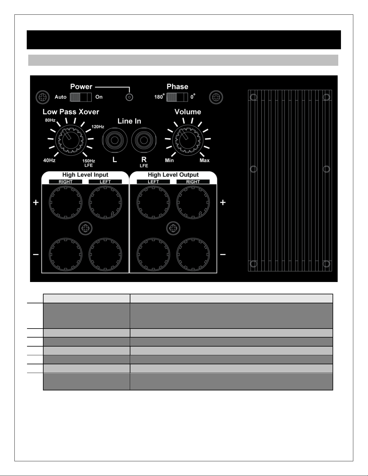
3 Product Overview
3.1 Connections and Controls
Name
Description
1
Power Sets power to always-on or automatically turn on when input
sound signal is detected. Power indicator light will turn blue
when on, or red in stand-by.
2
Phase Sets the output phase to 0 or 180 degrees.
3
Volume Sets the gain of the subwoofer amplifier.
4
Line In Line-level input RCA jacks. Use the LFE jack for mono signal.
5
Low Pass Xover Sets low-pass crossover frequency for the subwoofer.
6
High Level Input Speaker-level input for connecting from a power amplifier.
7
High Level Output Speaker-level signal pass-through to speakers – must be
used in conjunction with High Level Input.
Copyright © 2009-2017 Micca. All rights reserved. Page | 6
4 Placement Recommendations
Before connecting and setting up the Micca Media Series subwoofer, it is important to identify
the best location for placing the subwoofer to minimize the effect of room modes. Room modes
are frequencies at which a room acts as a reverberation chamber. The frequency and location of
these room modes are dependent on the size and shape of the room, but suffice to say all
rooms have room modes. Here are some general guidelines and best practices for placing
subwoofers within a listening environment to minimize the effect of room modes.
Near the Listening Position – The most predictable location to place a subwoofer is close by
the listener, which minimizes the effect of potential room modes. Popular locations include
behind the sofa or under a side table. Difficulties associated with this position are the length of
the subwoofer cable required, and access to a power plug.
Near the Front Main Speakers – The second best location is usually to place the subwoofer
near the front main speakers and pointed towards the listener. This location is more susceptible
to the effects of room modes, but the subwoofer can be moved left or right to identify a spot that
minimizes the modes at the listener’s position. One benefit of this location is that the
connections are much easier to make due to close proximity to other electronics and power
source.
Corner Near the Listener – The third best location is to place the subwoofer at a corner near
the listener. While corners are usually a bad location since it triggers the most room modes, the
corner that is closer to the listener has fewer potential issues. One positive with a corner
placement is that the output level is boosted due to reinforcement effect by the walls.
Far Corner Away From the Listener – The worst place to put a subwoofer is in a corner far
away from the listener. Unfortunately, this often the most popular place to put a subwoofer, since
it is usually along the same wall with the main speakers, and is tucked away in a corner. If being
visually hidden away is the most important consideration, this may be the only option available.
Notwithstanding the above, due to the unpredictable nature of room modes, the best location for
a particular application may in face be in a far corner away from the listener. Therefore, use the
above recommendations only as a general guideline and always let your ears make the final
decision as to the ideal location for a subwoofer.

Copyright © 2009-2017 Micca. All rights reserved. Page | 7
5 Connection and Setup
Micca Media Series subwoofer can be used in a variety of configurations, such as in a home
theater, or as bass augmentation for a pair of speakers. This chapter explains the various ways
in which the connections and settings should be used.
5.1 se With a Home Theater Receiver
This section explains how to use the Micca Media Series subwoofer with a home theater
receiver that is equipped with a subwoofer/LFE channel output. If your receiver or amplifier does
not have this output, please follow the directions in section 5.2. Refer to the diagram below for
making connections:
Locate the subwoofer/LFE output jack on the back of the home theater receiver, and use a
subwoofer cable of suitable length (not included) to connect to the subwoofer’s “Line In” jack
marked “R/LFE”. Leave the left input jack disconnected. Next, make the following settings on the
subwoofer’s back panel:
•Set power switch to “Auto”
•Set phase switch to “0”
•Set volume to the center position
•Set the low-pass crossover knob to 150Hz/LFE position

Copyright © 2009-2017 Micca. All rights reserved. Page | 8
Next, you must configure your receiver to use the subwoofer. Most modern home theater
receivers have auto calibration capabilities and can automatically set the subwoofer channel
volume, delay, and crossover frequency. If your home theater receiver does not have auto
calibration capabilities, these settings must be configured manually and are explained in the
receiver’s user manual. Please follow the instructions in your receiver’s manual for optimal
results.
5.2 se With a Stereo Amplifier
This section explains how to use the Micca Media Series subwoofer with a stereo amplifier or
receiver that does not have a subwoofer/LFE channel output. In this case, the subwoofer must
make use of the speaker level signals from the amplifier. Refer to the diagram below for making
connections:
First, make the following settings on the subwoofer’s back panel:
•Set power switch to “Auto”
•Set phase switch to “0”
•Set volume to the lowest position
•Set the low-pass crossover knob to 120Hz

Copyright © 2009-2017 Micca. All rights reserved. Page | 9
Next, using speaker wire (not included), connect the speaker outputs from the back of the
amplifier to the “High Level Input” on the subwoofer, making sure to match left-to-left, and right-
to-right. The connection between the amplifier and speakers can remain as is if it is difficult to
connect two sets of wires to the back of the amplifier, the speakers can be connected to the
“High Level Output” on the subwoofer instead. When speakers are connected to the “High Level
Output” on the subwoofer, the signal is passed through as-is without any crossover filtering.
Please select speaker wire thickness based on the following minimum recommendations:
•50 feet or less - 16 Gauge 2 Conductor
•50 to 80 feet - 14 Gauge 2 Conductor
•80 to 120 feet - 12 Gauge 2 Conductor (must use banana plug)
•120 to 200 feet - 10 Gauge 2 Conductor (must use banana plug)
Note: When working with speaker wire, it is important to make sure that wire strands are not
touching each other. Micca recommends using speaker wires with banana plugs for a clean and
reliable connection.
Next it is important to adjust the operating parameters of the subwoofer, which is best done with
a familiar piece of music with prominent bass. Follow the directions below:
•Play a familiar piece of music and set the playback volume to a comfortable level.
•Gradually increase the subwoofer volume until desired bass level is reached. There is a
natural tendency to add too much bass, so be patient in adding volume in small amounts.
•Try listening to the music with the phase switch in either the 0 or 180 degree position.
Keep it in the position that sounds the best. If they sound the same or similar, keep the
switch at the 0 position.
•For the low-pass crossover, most bookshelf speakers with a 4 to 6.5” woofer benefit from
a crossover setting between 80 to 120Hz. Adjust the knob within this range for the most
natural transition sound.
Copyright © 2009-2017 Micca. All rights reserved. Page | 10
5.3 se With Self-Powered Speakers
This section explains how to use the Micca Media Series subwoofer with a self-powered
speakers such as powered bookshelf speakers or studio monitors. The steps are different
depending on whether the self-powered speakers have a subwoofer output.
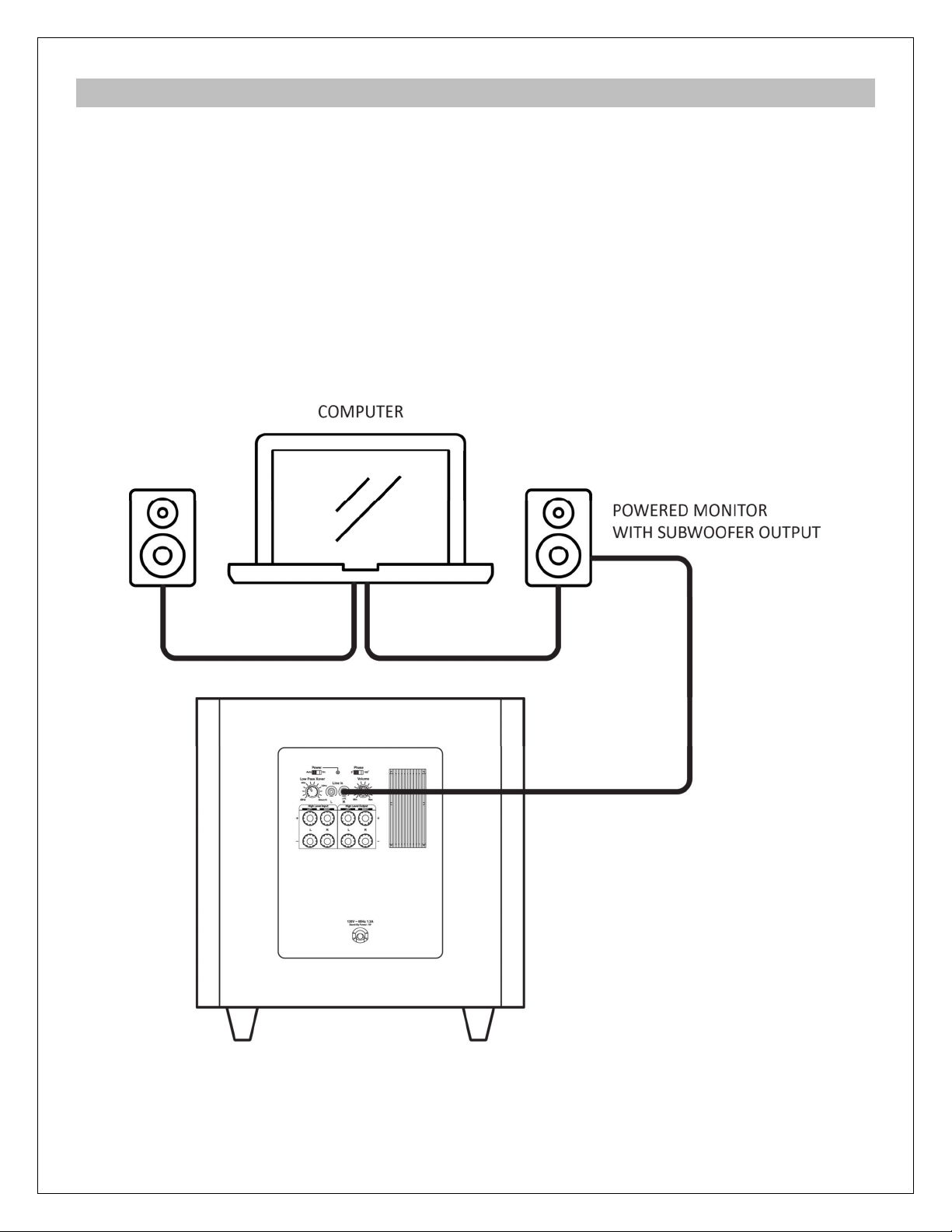
5.3.1 Self-Powered Speaker With Subwoofer Output
For self-powered speakers that have a subwoofer output, the connection is usually a 3.5mm
jack or standard RCA jack, use an appropriate cable (not included) to connect the output to the
“Line In” input jacks on the subwoofer. If the subwoofer output signal from the speakers is
stereo, connect it to both “L” and “R” jacks on the subwoofer. If the signal is mono, connect it to
the “R/LFE” input only leave the left input jack disconnected. Refer to the diagram below for
making connections:

Copyright © 2009-2017 Micca. All rights reserved. Page | 11
5.3.2 Self-Powered Speaker Without Subwoofer Output
To use a subwoofer with self-powered speakers not equipped with a subwoofer output, it is
necessary to use the music source as the volume control, and split the audio signal between the
speakers and the subwoofer. The most common way to do this is with a stereo Y-splitter (not
included).
With the source signal split using a stereo Y-splitter, connect one set of the split signal to the
self-powered speakers, and the other set to the “L” and “R” jacks on the subwoofer.
5.3.3 Settings and Adjustments
With the connections complete, make the following settings on the subwoofer’s back panel:
•Set power switch to “Auto”
•Set phase switch to “0”
•Set volume to the lowest position
•Set the low-pass crossover knob to 120Hz
Next it is important to adjust the operating parameters of the subwoofer, which is best done with
a familiar piece of music with prominent bass. Follow the directions below:
•Play a familiar piece of music and set the playback volume to a comfortable level.
•Gradually increase the subwoofer volume until desired bass level is reached. There is a
natural tendency to add too much bass, so be patient in adding volume in small amounts.
•Try listening to the music with the phase switch in either the 0 or 180 degree position.
Keep it in the position that sounds the best. If they sound the same or similar, keep the
switch at the 0 position.
•For the low-pass crossover, most bookshelf speakers with a 4 to 6.5” woofer benefit from
a crossover setting between 80 to 120Hz. Adjust the knob within this range for the most
natural transition sound.

Copyright © 2009-2017 Micca. All rights reserved. Page | 12
6 Specification
6.1 General
Power Source Voltage: ······················ 110-120VAC 60Hz
Maximum Current: ···························· 1.3A
Stand-by Power: ······························· 1W
Dimensions (MS10): ························· 14.2” (W) x 15.1” (H) x 16.6” (D)
360mm (W) x 384mm (H) x 421mm (D)
Weight (MS10): ································ 27.6lb (12.53kg)
Dimensions (MS12): ························· 16.1” (W) x 17.1” (H) x 18.5” (D)
410mm (W) x 435mm (H) x 471mm (D)
Weight (MS12): ································ 31.9lb (14.46kg)
6.2 Audio
RMS Power: ···································· 80 Watts
Peak Power: ···································· 120 Watts
Frequency Response (MS10): ············· 36Hz ~ 150Hz (in-room)
Frequency Response (MS12): ············· 29Hz ~ 150Hz (in-room)
Crossover Range: ····························· 40Hz ~ 150Hz
Phase: ············································ 0 or 180 Degrees
Input Sensitivity: ······························· 0.085 to 1.9Vrms
Auto-On Trigger: ······························· 0.006Vrms

Copyright © 2009-2017 Micca. All rights reserved. Page | 13
7 Micca Limited Warranty
Except where indicated differently, the following standard limited warranty is valid for Micca
Branded products. Where differences and contradictions occur, warranty terms in product-
specific description, listing, invoices, and receipts, those terms shall take precedence over the
following standard terms.
The manufacturer warrants all Micca Branded products against defects in materials and
workmanship for a limited period of 1 year, unless otherwise superseded by product-specific
description, listing, invoices, or receipts. During the limited period, the manufacturer will repair or
replace defective products at the manufacturer’s sole option. Customer must pay for all return
shipping costs during the limited period. The limited warranty period starts at the date of original
purchase. This limited warranty applies only to purchases from authorized Micca retailers. This
limited warranty is extended only to the original purchaser and is valid only to consumers in the
same country as the authorized retailer from which the original purchase was made.
This limited warranty only covers failures due to defects in materials or workmanship that occur
during normal use. It does not cover failures resulting from accident, fire, flood, misuse, abuse,
neglect, mishandling, misapplication, alteration, faulty installation, modification, service by
anyone other than the manufacturer, or damage that is attributable to Acts of God. It does not
cover costs of transportation to the manufacturer or damage in transit. Customers should return
defective products, freight prepaid and insured, to the manufacturer or authorized warranty
service center only after receiving a Return Merchandise Authorization (RMA). Customers are
required to provide a copy of the original sales invoice from an authorized retailer when making
a claim against this limited warranty.
Within the term of this warranty, defective products send to the manufacturer or authorized
warranty center for warranty service will be assessed a fee to cover shipping and handling of the
repaired or replacement product back to the customer. The fee amount depends on the product
and covers labor/handling, packaging materials, and standard shipping.
Repair or replacement under the terms of this warranty does not extend the term of this
warranty. Should a product prove to be defective in workmanship or material, the customer’s
sole remedies will be repair or replacement as provided under the terms of this warranty. If the
defective product is discontinued the manufacturer may replace the product with an equivalent
or superior product at its option. The limit of liability under this warranty is the original purchase
price of the product. Any cost of re-installation is the sole responsibility of the customer and that
cost shall not be the responsibility of the manufacturer. Under no circumstances shall the
manufacturer or its retailers be liable for loss or damage, direct, consequential or incidental,
arising out of the use of or inability to use the product. There are no express warranties other
than described above.

Copyright © 2009-2017 Micca. All rights reserved.
Information in this manual is believed to be accurate and reliable but Micca assumes no responsibility for its use nor for any
infringement of patents or other rights of third parties which may result from the use of this manual or the product. Micca
reserves the right to change product specifications at any time without notice.
Micca, MS10, MS12, and the Micca logo are trademarks of Micca. Other trademarks referenced in this manual are the
properties of their respective owners.
© 2017 Micca All rights reserved.
Other manuals for MS10
1
This manual suits for next models
1
Table of contents


