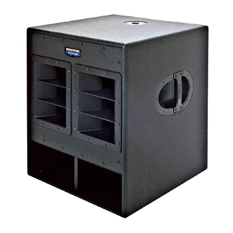
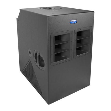
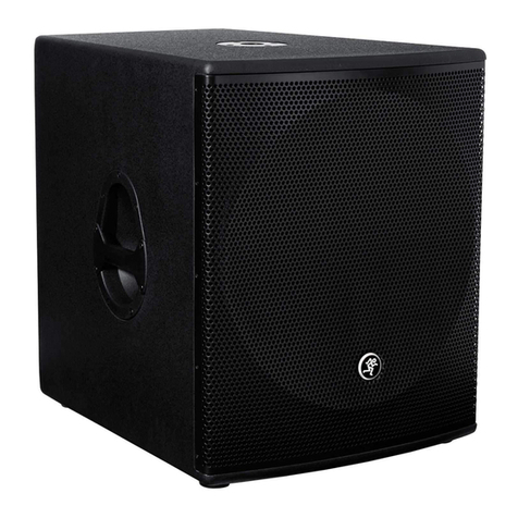
Mackie HD 1801 User manual

HD1801
OWNER’S MANUAL
18” Powered Subwoofer

1. Read these instructions.
2. Keep these instructions.
3. Heed all warnings.
4. Follow all instructions.
5. Do not use this apparatus near water.
6. Clean only with a dry cloth.
7. Do not block any ventilation openings. Install in accordance with the
manufacturer’s instructions.
8. Do not install near any heat sources such as radiators, heat registers,
stoves, or other apparatus (including amplifiers) that produce heat.
9. Do not defeat the safety purpose of the polarized or grounding-type
plug. A polarized plug has two blades with one wider than the other.
A grounding-type plug has two blades and a third grounding prong.
The wide blade or the third prong are provided for your safety. If the
provided plug does not fit into your outlet, consult an electrician for
replacement of the obsolete outlet.
10.
Protect the power cord from being walked on or pinched particularly at
plugs, convenience receptacles, and the point where they exit from the
apparatus.
11.
Only use attachments/accessories specified by the manufacturer.
12.
Use only with a cart, stand, tripod, bracket, or
table specified by the manufacturer, or sold with
the apparatus. When a cart is used, use caution
when moving the cart/apparatus combination to
avoid injury from tip-over.
13.
Unplug this apparatus during lightning storms or
when unused for long periods of time.
14.
Refer all servicing to qualified service personnel. Servicing is required
when the apparatus has been damaged in any way, such as power-
supply cord or plug is damaged, liquid has been spilled or objects have
fallen into the apparatus, the apparatus has been exposed to rain or
moisture, does not operate normally, or has been dropped.
15.
This apparatus shall not be exposed to dripping or splashing, and no
object filled with liquids, such as vases or beer glasses, shall be placed
on the apparatus.
16.
Do not overload wall outlets and extension cords as this can result in a
risk of fire or electric shock.
17.
This apparatus has been designed with Class-I construction and must
be connected to a mains socket outlet with a protective earthing con-
nection (the third grounding prong).
18.
This apparatus has been equipped with an all-pole, rocker-style AC
mains power switch. This switch is located on the rear panel and
should remain readily accessible to the user.
19.NOTE: This equipment has been tested and found to comply with
the limits for a Class B digital device, pursuant to part 15 of the FCC
Rules. These limits are designed to provide reasonable protection
against harmful interference in a residential installation. This equip-
ment generates, uses, and can radiate radio frequency energy and, if
not installed and used in accordance with the instructions, may cause
harmful interference to radio communications. However, there is no
guarantee that interference will not occur in a particular installation. If
this equipment does cause harmful interference to radio or television
reception, which can be determined by turning the equipment off and
on, the user is encouraged to try to correct the interference by one or
more of the following measures:
• Reorientorrelocatethereceivingantenna.
• Increasetheseparationbetweentheequipmentandthe
receiver.
• Connecttheequipmentintoanoutletonacircuitdifferentfrom
that to which the receiver is connected.
• Consultthedealeroranexperiencedradio/TVtechnicianfor
help.
CAUTION: Changes or modifications to this device not expressly
approved by LOUD Technologies Inc. could void the user's authority to
operate the equipment under FCC rules.
20.
This apparatus does not exceed the Class A/Class B (whichever is
applicable)
limits for radio noise emissions from digital apparatus as
set out in the radio interference regulations of the Canadian Department
of Communications.
ATTENTION — Le présent appareil numérique n’émet pas de bruits
radioélectriques dépassant las limites applicables aux appareils
numériques de class A/de class B (selon le cas) prescrites dans le
réglement sur le brouillage radioélectrique édicté par les ministere des
communications du Canada.
21.
Exposure to extremely high noise levels may cause permanent hearing
loss. Individuals vary considerably in susceptibility to noise-induced
hearing loss, but nearly everyone will lose some hearing if exposed to
sufficiently intense noise for a period of time. The U.S. Government’s
Occupational Safety and Health Administration (OSHA) has specified
the permissible noise level exposures shown in the following chart.
According to OSHA, any exposure in excess of these permissible limits
could result in some hearing loss. To ensure against potentially danger-
ous exposure to high sound pressure levels, it is recommended that all
persons exposed to equipment capable of producing high sound pres-
sure levels use hearing protectors while the equipment is in operation.
Ear plugs or protectors in the ear canals or over the ears must be worn
when operating the equipment in order to prevent permanent hearing
loss if exposure is in excess of the limits set forth here:
Important Safety Instructions
PORTABLE CART
WARNING
CAUTION AVIS
RISK OF ELECTRIC SHOCK. DO NOT OPEN
RISQUE DE CHOC ELECTRIQUE. NE PAS OUVRIR
CAUTION: TO REDUCE THE RISK OF ELECTRIC SHOCK DO NOT REMOVE COVER (OR BACK)
NO USER-SERVICEABLE PARTS INSIDE. REFER SERVICING TO QUALIFIED PERSONNEL
ATTENTION: POUR EVITER LES RISQUES DE CHOC ELECTRIQUE, NE PAS ENLEVER LE COUVERCLE.
AUCUN ENTRETIEN DE PIECES INTERIEURES PAR L'USAGER.
CONFIER L'ENTRETIEN AU PERSONNEL QUALIFIE.
AVIS: POUR EVITER LES RISQUES D'INCENDIE OU D'ELECTROCUTION, N'EXPOSEZ PA S CET ARTICLE
A LA PLUIE OU A L'HUMIDITE
The lightning flash with arrowhead symbol within an equilateral triangle is
intended to alert the user to the presence of uninsulated "dangerous
voltage" within the product's enclosure, that may be of sufficient magnitude
to constitute a risk of electric shock to persons.
Le symbole éclair avec point de flèche à l'intérieur d'un triangle équilatéral
est utilisé pour alerter l'utilisateur de la présence à l'intérieur du coffret de
"voltage dangereux" non isolé d'ampleur suffisante pour constituer un risque
d'éléctrocution.
The exclamation point within an equilateral triangle is intended to alert the
user of the presence of important operating and maintenance (servicing)
instructions in the literature accompanying the appliance.
Le point d'exclamation à l'intérieur d'un triangle équilatéral est employé
pour alerter les utilisateurs de la présence d'instructions importantes pour le
fonctionnement et l'entretien (service) dans le livret d'instruction
accompagnant l'appareil.
WARNING — To reduce the risk of fire or electric shock, do not
expose this apparatus to rain or moisture.
Duration,
per day in
hours
Sound Level
dBA, Slow
Response
Typical Example
8 90 Duo in small club
6 92
4 95 Subway Train
3 97
2 100 Veryloudclassicalmusic
1.5 102
1 105 Greg and Ben screaming at Troy
about deadlines
0.5 110
0.25 or less 115 Loudest parts at a rock concert
2
HD1801
HD1801

Contents
IMPORTANT SAFETY INSTRUCTIONS 2
CONTENTS 3
FEATURES 3
INTRODUCTION 3
HOOKUP DIAGRAMS 4
REAR PANEL FEATURES 8
INS AND OUTS OF POLARITY 11
RIGGING 12
PLACEMENT 14
Features
• 1600Wofultra-efcientClass-DFast
Recovery™amplication
•800WRMS/1600Wpeakpower
•133dBSPLmaxoutput(peak@1m)
•35Hz-145Hzoperatingrange
• 18”high-outputwooferwith4”voicecoil
• Activeelectronicsprovidecompletesystem
optimization
•SymmetricalLinkwitz-Rileycrossover
(100Hz,24dB/octave)
•Precisiontuningltersforultra-accurate
bassreproduction
•Phasealignmenttoperfectlycomplement
Mackiefull-rangeloudspeakers
• Ported,direct-radiatingdesignformaximum
punchandlow-frequencyextension
• DesignedandtunedbyEasternAcousticWorks
• DualXLRinputs,full-rangeandhigh-pass
outputsformonoorstereosetups
• Levelcontrolandpolarityinvertswitchwith
LEDindicator
• Signal/limitandthermalLEDindicators
• Integratedprotectionandlimitingcircuitry
• Ruggedall-woodcabinet(15mmbirchplywood)
• Polemountreceptacleformountingfull-range
speaker
• 12integratedM10ypoints
• Compactandlightweight(106lb/48.1kg)
THERMAL CONSIDERATIONS 14
AC POWER 14
CARE AND MAINTENANCE 14
APPENDIX A: SERVICE INFORMATION 15
APPENDIX B: CONNECTIONS 16
APPENDIX C: TECHNICAL INFORMATION 17
HD1801 GRAPHS AND DIMENSIONS 18
HD1801 BLOCK DIAGRAM 19
HD1801 LIMITED WARRANTY 20
Introduction
ThankyouforchoosingtheMackieHD1801
subwoofer.MackieHDSeriesPoweredSubwoofers
provideintenselow-frequencyextensionandpunchto
anyMackiefull-rangesystem.Designedandtunedby
theexpertsatEAW,HD1801subsdeliver1600Wpeak
powerviahigh-output18”driverscustom-designedfor
optimalpairingwithMackiefull-rangeloudspeakers.
TheHD1801incorporatesMackie-standardprofessional
componentslikeefcientClass-DFastRecovery™
ampliersandsystem-optimizingActiveelectronicsso
thateverythingsoundsgreatrightoutofthebox.
PremiumcircuitryincludesasymmetricalLinkwitz-
Rileycrossover,precisiontuningltersanduser-friendly
featureslikehighpassoutputsforstereooperationwith
asinglesub.The15mmbirchplywoodenclosures
featureaported,direct-radiatingdesignforchest-
poundingpunch.PairtheHD1801withanyMackie
full-rangeloudspeakerforanextremelypowerfuland
fullyhigh-denitionPAsolution.
PairedwithaMackieHDSeriesloudspeaker,youhave
acomplete(andcompletelyaffordable)“plugandplay”
systemthatisidealforsmallclubs,DJsandrehearsal
spaces.TheHD1801hasbothfull-rangeandhigh-pass
stereooutputsforconnectiontofull-rangetopboxes.
Justdialintheappropriatelevelandusethepolarity
switchtomakesurethesubisinphasewiththe
loudspeakers.Theintegratedpole-cupcan
accommodateastandardmountingpole,soyour
favoritespeakerhasaniceplacetosit.Youcanyit
usingtheintegratedM10ypoints.Oryoucanjuststack
yourfull-rangeboxrightontopofthesub...theHD1801
ain’tpicky.
Soifyouarelookingforanextremelypowerful,
affordablePAsetupthatissimpletouse,thenyou’rein
therightplace.Readontolearneverythingyoucould
possiblywanttoknowaboutyournewsubwoofer.
3
Owner’s Manual
Owner’s Manual
PartNo.SW0822Rev.B01/10
©2004-2010 LOUD Technologies Inc. All Rights Reserved.

HD1801: 3-WAY SYSTEM - MONO SUBWOOFER WITH SRM450V2 LOUDSPEAKERS
Hookup Diagrams
This diagram shows the left and right line level outputs of a Mackie CFX12mkII mixer feeding inputs
A and B of one Mackie HD1801 subwoofer. Two SRM450v2 loudspeaker inputs are fed from the A and
B High Pass outputs from the subwoofer. Experiment with the HD1801’s polarity switch to achieve
optimum performance. Placement of the subwoofer relative to the full-range loudspeakers will also affect
performance. See page 10 for more information.
1 2 3 4 5 6 7 8 9-10 11-121234
SRM450v2
reproduces all
frequencies
above the
subwoofer’s
crossover point
Left
line level
output
Right
line level
output
Po wer
Cord
Line-level
High Pass
output B
SRM450v2
reproduces all
frequencies
above the
subwoofer’s
crossover point
Po wer
Cord
Line-level
High Pass
output A
HD1801
input A
HD1801
input B
Po wer
Cord
HD1801 subwoofer
reproduces the
low frequencies
CFX12mkII
Mixer
4
HD1801
HD1801

HD1801: 3-WAY SYSTEM - MONO SUBWOOFER WITH HD1521 LOUDSPEAKERS
This diagram shows the left line level output of a Mackie 1604-VLZ3 mixer feeding input A of one
Mackie HD1801 subwoofer. Two HD1521 loudspeaker inputs are fed from the A and B High Pass
outputs from the subwoofer. Experiment with the HD1801’s polarity switch to achieve optimum
performance. Placement of the subwoofer relative to the full-range loudspeakers will also affect
performance. See page 10 for more information.
Left
line level
output
Right
line level
output
Po wer
Cord
Line-level
High Pass
output B
Po wer
Cord
Line-level
High Pass
output A
HD1801
input A
HD1801
input B
Po wer
Cord
HD1801 subwoofer
reproduces the
low frequencies
1604-VLZ3
Mixer
HD1521 reproduces
all frequencies
above the subwoofer’s
crossover point
HD1521 reproduces
all frequencies
above the subwoofer’s
crossover point
5
Owner’s Manual
Owner’s Manual

HD1801: STEREO 4-WAY SYSTEM WITH HD1531 LOUDSPEAKERS
This diagram shows the left and right line level outputs of a Mackie Onyx 1620i mixer feeding input A
of two Mackie HD1801 subwoofers. The High Pass output A of each subwoofer then feeds the input of
each Mackie HD1531 loudspeaker. Be sure to engage the Polarity Invert switch on the HD1801
subwoofers to optimize performance. See page 10 for more information.
Left
line level
output
Right
line level
output
Po wer
Cord
Po wer
Cord
Pole
Mount
Pole
Mount
Line-level
High Pass
output A
Line-level
High Pass
output B
HD1801
input B
HD1801
input A
Po wer
Cords
Po wer
Cords
HD1801 subwoofer
reproduces the
low frequencies
HD1801 subwoofer
reproduces the
low frequencies
Onyx 1620i
Mixer
HD1531
reproduces all
frequencies
above the
subwoofer’s
crossover point
HD1531
reproduces all
frequencies
above the
subwoofer’s
crossover point
6
HD1801
HD1801

HD1801: STEREO 4-WAY SYSTEM WITH HD1531 LOUDSPEAKERS AND DUAL SUBWOOFERS
This diagram shows the left and right line level outputs of a Mackie Onyx 1640i mixer feeding input
A of two Mackie HD1801 subwoofers. The Full Range output A of each subwoofer then feeds input A of
another pair of Mackie HD1801 subwoofers. The High Pass output A of these subwoofers then feed the
input of each Mackie HD1531 loudspeaker. Be sure to engage the Polarity Invert switch on the HD1801
subwoofers to optimize performance. See page 10 for more information.
NOTE: It is highly recommended that you use straps to secure your loudspeakers for stacked scenarios
such as this one. Be sure to loop a strap through each handle going down each side of the cabinet setup,
as shown above.
Left
line level
output
Right
line level
output
Line level
High Pass
output A
Line level
High Pass
output A
Full Range
output A
to HD1801
input A
Full Range
output A
to HD1801
input A
Po wer
Cord
Po wer
Cord
Po wer
Cord
Po wer
Cord
Po wer
Cord
Po wer
Cord
HD1801 subwoofers
reproduce the low
frequencies
HD1801 subwoofers
reproduce the low
frequencies
Onyx 1640i
Mixer
HD1531
reproduces all
frequencies
above the
subwoofers’
crossover point
HD1531
reproduces all
frequencies
above the
subwoofers’
crossover point
to HD1801
inputs A
Straps Straps
7
Owner’s Manual
Owner’s Manual

Rear Panel Features
1. IEC AC Receptacle
Thisjackacceptsthesupplied3-prongACpowercord.
BeforeyouplugtheACpowercordintothe
poweredsubwoofer,makesurethatthe
voltageofyourunitisthesamevoltageasyour
localACmainssupply.Useonlythepower
cordsupplied.Also,disconnectingtheplug’sgroundpin
isdangerous.Don’tdoit.
2. POWER
UsethisswitchtoturntheHD1801onandoff.The
LEDabovetheswitchwillilluminatewhenpoweredon.
ThefrontpanelLEDwillalsoturnon,butonlyifthe
POWERLIGHTONswitch(7)isengaged.Pressthe
bottomofthisswitchtoturnthesubwooferoff.
Asageneralguide,poweredsubwoofers
shouldbeturnedonafterthemixerandother
sources,butpriortofull-rangespeakers.
Additionally,theyshouldalsobepoweredoff
afterthetops,butbeforethemixerandothersources.
Thiswillreducethepossibilityofanyturn-on,orturn-
offthumpsinyourspeakers.
POWER
1 8 - INCH HIG H DEF INITI ON PO WERED S UBW OOFER
ON
RE VI SI ON
SE RI AL NU MB ER
WARNING:
TO REDUCE THE RISK OF FIRE OR ELECTRIC SHOCK, DO NOT EXPOSE THIS EQUIPMENT TO RAIN OR
MOISTURE. DO NOT REMOVECOVER. NO USER SERVICEABLE PARTS INSIDE. REFER SERVICINGTO QUALIFIED PERSONNEL.
AVIS:
RISQUE DE CHOC ELECTRIQUE — NE PAS OUVRIR
SETTINGS
POWER
LIGHT ON
SIG/ LIMIT
THERMAL
LEVEL
POLARITY
INVERT
FULL RANGE
HIGH PASS
OUTPUTS
A B
A B
A B
INPUTS
+6dB 6d B
-
HD1801
8
HD1801
HD1801
1
2
4
5
6
7
10
3
9
8

3. INPUTS
ThesefemaleXLRconnectorsacceptbalanced
line-levelsignalsfromamixingconsoleorothersignal
source.
Ifyouareconnectingasinglesubwooferoutput,or
LFE(low-frequencyeffects)outputtothesubwoofer,
youmayuseeithertheAorBinputconnector.
CAUTION:
NEVERconnecttheoutputofan
amplierdirectlytotheinputofthe
subwoofer.Thiscoulddamagetheinput
circuitryofthepoweredsubwoofer.
4. HIGH PASS OUTPUTS
BalancedXLRmaleconnectorsareprovidedforthe
line-levelAandBhigh-passoutputs.Thesubwoofer’s
internalactivecrossoversplitstheinputsignalsinto
twofrequencybands.Thelowfrequencyrangebelow
100Hzgoestotheinternalamplierthatpowersthe
subwoofer.Thefrequencyrangeabove100Hzissentto
theseline-leveloutputjacks.
Connecttheseoutputstotheinputsofyourmain
poweredloudspeakers,ortotheinputsoftheamplier
poweringthemainloudspeakers.Inthisway,themain
loudspeakerswillplaytherangeabove100Hz.Ifthe
mainloudspeakershavegoodlow-frequencyresponse,
thenyoumaydecidetousethefull-rangeoutputs(5)
instead.
Thelevelcontrolandpolarityswitchhavenoeffect
onthehigh-passoutputs.Theoutputsareseparateand
maintainthestereoseparationoftheinputsignals.
5. FULL RANGE OUTPUTS
BalancedXLRmaleconnectorsareprovidedforthe
line-levelAandBfull-rangeoutputs.Connectthese
outputstotheinputsofanotherpoweredsubwoofer,
mainpoweredloudspeakers,ortoanamplierpowering
passiveloudspeakers.
Thesignalattheseoutputsisadirectcopyofthe
inputsignals.Theseoutputsallowyoutodaisy-chain
multiplesubwoofers,and/orsendthefull-rangesignals
tothemainloudspeakers.
Thelevelcontrolandpolarityswitchhavenoeffect
onthefull-rangeoutputs.Theoutputsareseparateand
maintainthestereoseparationoftheinputsignals.
6. POLARITY INVERT
Pressthisswitchintoinvertsubwooferpolarity.
DependingontheplacementoftheHD1801subwoofer
relativetothefull-rangespeakers,youmaygetabetter
low-frequencyresponseifyouinvertthepolarityofthe
subwoofer’ssignal.Seepage11formoreinformation.
7. POWER LIGHT ON
Pressthisswitchintoturnonthefrontpanelpower
LEDifavisualindicatorispreferred.TheLEDnextto
theswitchwilllightasareminder.
Ifthisswitchisout,andtheHD1801isturnedon,the
LEDonthefrontofthecabinetwillnotlight,norwill
theLEDnexttotheswitch.
8. LEVEL
Thiscontrolstheoverallsignallevelattheinputto
thebuilt-inpoweramplier.Itrangesfrom–6dBto
+6dBofgain.Thecenterdetentis0dB(unitygain).
ThiscontrolhasnoeffectontheleveloftheHigh
PassOutputs(4)ortheFullRangeOutputs(5).
POWER
18 - INCH HIGH DEFINITION POWERED SUBWOOFER
ON
REVISION
SERIAL NUMBER
WARNING:
TO REDUCE THE RISK OF FIRE OR ELECTRIC SHOCK, DO NOT EXPOSE THIS EQUIPMENT TO RAIN OR
MOISTURE. DO NOT REMOVE COVER.NO USER SERVICEABLE PARTS INSIDE.REFER SERVICING TO QUALIFIED PERSONNEL.
AVIS:
RISQUE DE CHOC ELECTRIQUE — NE PAS OUVRIR
SETTINGS
POWER
LIGHT ON
SIG/ LIMIT
THERMAL
LEVEL
POLARITY
INVERT
FULL RANGE
HIGH PASS
OUTPUTS
A B
A B
A B
INPUTS
+6dB 6dB
-
HD1801
4
5
6
7
10
3
9
8
9
Owner’s Manual
Owner’s Manual

POWER
18 - INCH HIGH DEFINITION POWERED SUBWOOFER
ON
REVISION
SERIAL NUMBER
WARNING:
TO REDUCE THE RISK OF FIRE OR ELECTRIC SHOCK, DO NOT EXPOSE THIS EQUIPMENT TO RAIN OR
MOISTURE. DO NOT REMOVE COVER.NO USER SERVICEABLE PARTS INSIDE.REFER SERVICING TO QUALIFIED PERSONNEL.
AVIS:
RISQUE DE CHOC ELECTRIQUE — NE PAS OUVRIR
SETTINGS
POWER
LIGHT ON
SIG/ LIMIT
THERMAL
LEVEL
POLARITY
INVERT
FULL RANGE
HIGH PASS
OUTPUTS
A B
A B
A B
INPUTS
+6dB 6dB
-
HD1801
9. SIG/LIMIT LED
Thisbi-colorLEDilluminatesgreenwheneverthereis
asignalpresentatthemaininputs.Itsensesthesignal
justafterthelevelcontrol,soadjustmentstothelevel
controlwillaffectthesig/limitindicator.
TheHD1801hasabuilt-inlimiterthathelpstopre-
venttheamplieroutputsfromclippingoroverdriving
thetransducer.Thesig/limitindicatorlightsinyellow
whenthelimiterisactivated.It’sokayforittoblink
yellowoccasionally,butifitblinksfrequentlyorlights
continuously,turndowntheinputleveluntilitonly
blinksoccasionally.
Excessivelimitingmayleadto
overheating,whichinturntripsthethermal
protectcircuitryandinterruptsthe
performance.See‘ThermalConsiderations’on
page14formoreinformation.
10. THERMAL LED
TheHD1801isequippedwithathermalprotection
circuitthatmonitorstheinternaltemperatureofthe
amplierandheatsink.Ifthetemperaturebeginsto
exceedasafeoperatinglevel,thisindicatorlightsand
theamplieroutputislimitedtoallowtheamplierto
cool.Iftheamplierbecomesexcessivelyhot,theampis
muteduntilitcools,thentheHD1801returnstonormal
operation.
WhentheHD1801isinthermalprotectmode,the
powerLED(2)willremainlit,indicatingthattheunit
isstillpoweredondespitethelackofoutput.IfPOWER
LIGHTON(7)isengaged,thefrontpanelpowerLED
willgooutwheninthermalprotectmode.
Activationofthethermalprotectioncircuit
isanindicationthatyoushouldtakesteps
toavoidcontinuedthermalproblems.See
“ThermalConsiderations”onpage14.
10
HD1801
HD1801
4
5
6
7
10
3
9
8

The Ins and Outs of Polarity
Mackie’sHD-SeriesPoweredSubwoofersincludea
switchthatallowsyoutoquicklyinvertthepolarityof
thesubwoofer’soutputrelativetotheinputsignalitis
receivingfromthemixerorothersoundsource.But
whatexactlydoesthatmean?Asubwooferworksbylit-
erallypumpingairasthewooferconemovesinandout
withrespecttothecabinetinwhichitishoused.Itdoes
soaccordingtothelow-frequencyportionofthesignalit
receivesfromthesoundsource.
Thewooferconeissimplyfollowingthewaveform
asseeninthesinewaveinFigure1.Asthesinewave
rises,thewooferconepushesout.Likewise,asthesine
wavefalls,thewooferconepullsintothecabinet.A
musicalsignalismuchmorecomplex,ofcourse,butthe
sameprincipleapplies.Movementofthewoofercone
causesairpressurechangesthatweperceiveassound.
WhenthePolarityInvertswitch[6]isengaged,the
originalwaveformissimplyreversed180º(seeFigure
2).Again,thesubwooferconefollowsthewaveform.
However,thistimethewooferconestartsbypullinginto
thecabinetfollowedbythewooferconepushingout.If
youhaveeverexperimentedwithasubwooferpolarity
switch,youmaynothavenoticedanychangestothe
soundregardlessofitsposition,especiallyifyouare
listeningtojustthesubwoofer.Thisisnormal,asour
earsperceivethembothasthesame.
Thepolarityinvertswitchcomesintoplaywhenthe
HD1801subwooferispairedwithaloudspeaker.Ideally,
thewooferconesofthesubwooferandfull-rangeloud-
speakerwouldworktogetherbypushingandpullingin
unison.HD-Seriessubwoofersaredesignedtobeused
inabroadrangeofapplications,andwithawidevariety
offull-rangeloudspeakers.Theexibilityprovidedby
thepolarityswitchisnecessarytoensurethatyouare
receivingthebestpossiblesoundfromyoursystem,
regardlessofyoursetup.
Listedbelowaresomerecommendedcongurations
forpairingaMackieHD-Seriessubwoofer(usingthe
High-Passoutput)withaMackiefull-range
loudspeaker.Thesesettingsareagoodstart,butbesure
toexperimenttondthebestsoundforyourvenue.The
loudspeakersmaybestacked,pole-mounted,orown.
•HD-Series full-range loudspeakers-Engagethe
PolarityInvertswitchontheHD1801.
•SRM450v2 full-range loudspeakers-Disengagethe
PolarityInvertswitchontheHD1801.Engagethe
LowCutFilterswitchontheSRM450v2loudspeaker.
Inalternatesetupswherethefull-rangeloudspeakers
arenotco-locatedwiththesubwoofersorarenot
connectedtotheHD-Seriessubwoofer’sHigh-Pass
outputs,youwillneedtoexperimentwiththePolarity
Invertswitchtodeterminewhichsettinggivesyouthe
desiredbassresponseforyourapplication.
Figure 1 Figure 2
< - - T i m e - - > < - - T i m e - - >
Amplitude
Amplitude
11
Owner’s Manual
Owner’s Manual

12 Fly Points
Rigging Hardware and Accessories
RiggingMackiesubwooferswillinvariablyrequire
hardwarenotsuppliedbyMackie.Varioustypesof
load-ratedhardwareareavailablefromavarietyof
third-partysources.Thereareanumberofsuch
companiesspecializinginmanufacturinghardwarefor,
designing,andinstallingriggingsystems.Eachoneof
thesetasksisadisciplineinitsownright.Becauseof
thehazardousnatureofriggingworkandthepotential
liability,engagecompaniesthatspecializeinthese
disciplinestodotheworkrequired.
Mackiedoesoffercertainaccessoryriggingitems,
primarilyforattachmenttothehardwareintegralwith
thesubwoofer.Someitems,suchaseyebolts,maybe
usedwithavarietyofproducts.Whiletheseaccessories
areintendedtofacilitateinstallation,thewidevarietyof
possibleinstallationconditionsandarraycongurations
donotpermitMackietodeterminetheirsuitabilityor
loadratingforanyparticularapplication.
Mackieisnotinthebusinessofprovidingcomplete
riggingsystems,eitherasdesigners,manufacturers,or
installers.Itistheresponsibilityoftheinstallerto
provideaproperlyengineered,load-certiedrigging
systemforsupportingthesubwooferfromstructure.
Rigging Notes
TheHD1801’sintegralmountingpointsaredesigned
tosupportonlytheweightoftheirownsubwoofer,
orincombinationwith(1)oneHD-Seriesfull-range
loudspeaker,withsuitable,externalhardware.This
meansthateachHDsubwoofer,aloneorpairedwithan
HD-Seriesfull-rangeloudspeaker,mustbesupported
independentlyofanyotherHDsubwooferandanyother
loads.
Aminimumoftworiggingpointsmustbeusedtohang
anHD1801.Moremaybeusedforcreatingthedesired
hangingangleasshownintheillustrationsonpage12.
Allmountingpointsarefullyloadbearingsoanytwo
maybeusedforrigging;nomountingpointsare
restrictedtoanglecontrolonly.
Rigging
HD1801smaybeindividuallyownusingM10x1.5x
37mmforgedshouldereyebolts.
WARNING:Installationshouldonlybedone
byanexperiencedtechnician.Improper
installationmayresultindamagetothe
equipment,injuryordeath.Makesurethatthe
subwooferisinstalledinastableandsecurewayin
ordertoavoidanyconditionsthatmaybedangerousfor
personsorstructures.
WARNING:Thecabinetisonlysuitablefor
riggingviaitsypoints.NEVERattemptto
suspendtheHD1801byitshandles.
Rigging Design Practices
Riggingasubwooferrequiresdetermining:
1.Theriggingmethodsandhardwarethatmeetstatic,
shock,dynamic,andanyotherloadrequirementsfor
supportingthesubwooferfromstructure.
2.ThedesignfactorforandtherequiredWLL
(WorkingLoadLimit)forthissupport.
Mackiestronglyrecommendsthefollowingrigging
practices:
1.Documentation:Thoroughlydocumentthedesign
withdetaileddrawingsandpartslists.
2.Analysis:Haveaqualiedprofessional,suchasa
licensedProfessionalEngineer,reviewandapprovethe
designbeforeitsimplementation.
3.Installation:Haveaqualiedprofessionalriggerdo
theinstallationandinspection.
4.Safety:Useadequatesafetyprecautionsand
back-upsystems.
Two per side Two on the rear Three each on the top and bottom
HD1801
MP MP MP
MP MP
MP MP
MP=MountingPoint
12
HD1801
HD1801

HD1801 with a Mackie HD1531 Flown VerticallyHD1801 with a Mackie HD1521 Flown Horizontally
Lower Rear
Fly Point
(adjusts angle)
Lower Rear
Fly Point
(adjusts angle)
Bottom
Fly Point
Bottom
Fly Point
Rear Fly Points
(adjusts angle)
Important Rigging Reminder:
Toreiterate,Mackieisnotinthebusinessofproviding
completeriggingsystems,eitherasdesigners,
manufacturers,orinstallers.Itistheresponsibilityof
theinstallertoprovideaproperlyengineered,load-cer-
tiedriggingsystemforsupportingthesubwooferfrom
structure.
Theillustrationsprovidedbelowarejustacoupleof
riggingpossibilities.
Lower Rear
Fly Point
(adjusts angle)
13
Owner’s Manual
Owner’s Manual

Placement
Asmentionedintheprevioustwopages,HD1801
subwoofersmaybeown.However,theyaredesignedto
sitontheoororstage,aswell.Asocketis
providedontopoftheHD1801formountingother
Mackieloudspeakers.Useasuitablespeakermounting
poletomountthemontheHD1801.Seethehookup
diagramsstartingonpage4.
Checktomakesurethatthesupportsurface(e.g.,
oor,etc.)hasthenecessarymechanicalcharacteris-
ticstosupporttheweightoftheloudspeaker(s)and
subwoofer(s).
Whenpole-mountingloudspeakers,besurethatthe
HD1801subwoofersarestabilizedandsecuredfrom
fallingoverorbeingaccidentallypushedover.For
stackedscenarios,itishighlysuggestedthatstrapsare
utilized.Failuretofollowtheseprecautionsmayresult
indamagetotheequipment,personalinjury,ordeath.
Aswithanypoweredcomponents,protectthemfrom
moisture.Avoidinstallingthesubwooferinplaces
exposedtoharshweatherconditions.Ifyouaresetting
themupoutdoors,makesuretheyareundercoverifyou
expectrain.
Thermal Considerations
TheHD1801hasapowerfulbuilt-inampliercapable
ofproducing800wattsofrmspower.Asanamplier
works,itproducesheat.Thehigherthesignallevel,the
louderandhotteritgets.Itisimportanttodissipatethe
heatasquicklyaspossible.Thisresultsinincreased
reliabilityandlongevityfortheamplier.
Theampliermoduleiscooledbytwin
thermally-controlledvari-speedfans.Inorderforthis
coolingsystemtoworkefciently,itisimportantto
provideadequateairspacebehindthesubwoofer.When
positioningtheHD1801,werecommendleavingatleast
sixinchesofairspacebehindit.
Intheunlikelyeventoftheamplieroverheating,a
built-inthermalswitchwillactivate,mutingthe
amplier’soutput.Whentheamplierhascooleddown
toasafeoperatingtemperature,thethermalswitch
resetsitself,andtheHD1801resumesnormaloperation.
Ifthethermalswitchactivatesfrequently,tryturning
downthelevelcontrolanotchortwoonthemixing
console(orthebackoftheHD1801)toavoid
overheatingtheamplier.Beawarethatdirectsunlight
and/orhotstagelightsmaybethecauseofanamplier
overheating.
AC Power
BesuretheHD1801ispluggedintoanoutletthat
isabletosupplythecorrectvoltagespeciedforyour
model.Itwillcontinuetooperateatlowervoltages,but
willnotreachfullpower.
Besuretheelectricalservicecansupplyenough
amperageforallthecomponentsconnectedtoit.
Werecommendthatastiff(robust)supplyofAC
powerbeusedbecausetheamplierplaceshigh
currentdemandsontheACline.Themorepowerthatis
availableontheline,thelouderthesubwooferwillplay
andthemorepeakoutputpowerwillbeavailablefora
cleaner,punchierbass.Asuspectedproblemof“poor
bassperformance”isoftencausedbyaweakACsupply
totheamplier.
Neverremovethegroundpinonthepower
cordoranyothercomponentoftheHD1801.
Thisisverydangerous.
Care and Maintenance
YourMackiesubwooferswillprovidemanyyearsof
reliableserviceifyoufollowtheseguidelines:
• Avoidexposingthesubwooferstomoisture.If
theyaresetupoutdoors,besuretheyareunder
coverifrainisexpected.
• Avoidexposuretoextremecold(below
freezingtemperatures).Ifyoumustoperatethe
subwoofersinacoldenvironment,warmupthe
voicecoilsslowlybysendingalow-levelsignal
throughthemforabout15minutespriorto
high-poweroperation.
• Useadryclothtocleanthecabinets.Onlydo
thiswhenthepoweristurnedoff.Avoidgetting
moistureintoanyoftheopeningsofthecabi-
net,particularlywherethedriverislocated.
14
HD1801
HD1801

Poor bass performance
• Checkthepolarityoftheconnectionsbetween
themixerandthesubwoofers.Youmayhave
yourpositiveandnegativeconnectionsreversed
atoneendofonecable,causingonesubwoofer
tobeout-of-phase.
• Checkyoursubwooferpolarityswitchesare
conguredappropriatelyforyoursetup.See
page10formoreinformation.
Poor sound
• Isitloudanddistorted?Makesurethatyou’re
notoverdrivingastageinthesignalchain.
Verifythatalllevelcontrolsaresetproperly.
• Istheinputconnectorpluggedcompletelyinto
thejack?Besureallconnectionsaresecure.
Noise
• Makesureallconnectionstothepowered
subwoofersaregoodandsound.
• Makesurenoneofthesignalcablesarerouted
nearACcables,powertransformers,orother
EMI-inducingdevices.
• IstherealightdimmerorotherSCR-based
deviceonthesameACcircuitastheHD1801?
UseanAClinelterorplugtheHD1801intoa
differentACcircuit.
Hum
• Trydisconnectingthecableconnectedtothe
maininputjack.Ifthenoisedisappears,it
couldbea“groundloop,”ratherthanaproblem
withtheHD1801.Trysomeofthefollowing
troubleshootingideas:
•Usebalancedconnectionsthroughoutyour
systemforthebestnoiserejection.
•Wheneverpossible,plugalltheaudio
equipment’slinecordsintooutletswhich
shareacommonground.Thedistance
betweentheoutletsandthecommon
groundshouldbeasshortaspossible.
IfyouthinkyourMackieproducthasaproblem,
pleasecheckoutthefollowingtroubleshootingtipsand
doyourbesttoconrmtheproblem.VisittheSupport
sectionofourwebsite(www.mackie.com/support)
whereyouwillndlotsofusefulinformationsuchas
FAQsandotherdocumentation.Youmayndtheanswer
totheproblemwithouthavingtosendyourMackie
productaway.
Troubleshooting
No power
• Isitpluggedin?MakesuretheACoutletislive
(checkwithatesterorlamp).
• Ournextfavoritequestion:Isthepowerswitch
on?Ifnot,tryturningiton.
• IsthepowerLEDontherearpanelglowing
green?Ifnot,makesuretheACoutletislive.If
so,referto“Nosound”below.
• TheinternalAClinefusemaybeblown.Thisis
notauserserviceablepart.Ifyoususpectthe
AClinefuseisblown,pleaseseethe"Repair"
sectionnext.
No sound
• Istheinputlevelcontrolfortheinputsource
turnedallthewaydown?Verifythatallthe
volumecontrolsinthesystemareproperly
adjusted.
• Isthesignalsourceworking?Makesurethe
connectingcablesareingoodrepairand
securelyconnectedatbothends.Makesurethe
outputvolume(gain)controlonthemixing
consoleisturnedupsufcientlytodrivethe
inputsofthespeaker.
• MakesurethemixerdoesnothaveaMuteon
oraProcessorloopengaged.Ifyound
somethinglikethis,makesurethevolume/
gainisturneddownbeforedisengagingthe
offendingswitch.
• Isthethermalindicatorlitredontherear
panel?Makesurethereisatleastsixinchesof
freespacebehindtheHD1801.
Appendix A:
Service Information
15
Owner’s Manual
Owner’s Manual

Appendix B:
Connections
XLR Connectors
TheHD1801hastwofemaleXLRinputsthataccept
balancedline-levelsignals.Whenconnectingabalanced
signal,besureit’swiredperAES(AudioEngineering
Society)standards:
XLR
Pin1–Shield(Ground)
Pin2–Hot(+)
Pin3–Cold(–)
TherearealsotwomaleXLRconnectorsonthe
HD1801labeledfullrange.Thesearealsowired
accordingtotheAESstandardslistedabove.
Thefullrangeconnectorsallowyoutoconnect
severalHD1801’s.Simplyplugthesignalsource
(e.g.,mixeroutput)intotheHD1801inputjack,and
patchthatsubwoofer’sfullrangejacktothenext
subwoofer’sinputjack,andsoon,daisy-chaining
multiplesubwoofers.
Thereisalimittohowmanyyoucan
daisy-chaintogether.Ageneralruleisto
maintainaloadimpedancetentimesor
morethanthesourceimpedancetoprevent
excessiveloadingonthesource.Forexam-
ple,ifyourmixerhasanoutputimpedanceof120ohms,
thenyoucandaisychainuptonineHD1801s.Thisis
aloadof1222ohms(HD1801inputimpedance=11
kohms;9oftheseinparallel=1222ohms).Since
microphonestypicallyhaveahigheroutputimpedance,
youshouldlimitdaisy-chainingfromamicsourcetotwo
HD1801s(assumingthatloudspeakersarealsocon-
nectedtothesubwoofers).
Balanced XLR Connectors
Repair
Forwarrantyservice,refertothewarranty
informationonpage19.
Non-warrantyserviceforMackieproductsis
availableatafactory-authorizedservicecenter.To
locatethenearestservicecenter,visitwww.mackie.com,
click“Support”andselect“LocateaServiceCenter.”
ServiceforMackieproductslivingoutsidetheUnited
Statescanbeobtainedthroughlocaldealersor
distributors.
Ifyoudonothaveaccesstoourwebsite,youmaycall
theTechSupportdepartmentat1-800-898-3211,
Monday-Friday,duringnormalbusinesshours,Pacic
Time,toexplaintheproblem.TechSupportwilltellyou
wherethenearestfactory-authorizedservicecenteris
locatedinyourarea.
16
HD1801
HD1801

Acoustic Performance
Frequency Response (–10 dB): 35 Hz – 145 Hz
Frequency Response (–3 dB): 44 Hz – 95 Hz
Max peak SPL (calculated)1: 133 dB
Max peak SPL (measured)2: 129 dB
Transducer
Diameter: 18.0 in / 457 mm
Voice Coil Diameter: 4.0 in / 102 mm
Diaphragm Material: Paper
Magnet Material: Ferrite
Power Amplier
Rated Power: 800 watts rms
1600 watts peak
THD: < 0.03%
Design: Class D
Cooling: Active, twin thermally
controlled vari-speed
fans
Input/Output
Input Type: Female XLR Balanced
differential
(stereo left/right)
Input Impedance: 20 k
Full Range Output: Male XLR Balanced
(parallel with input)
High Pass Output: Male XLR Balanced
Output Impedance: 300
Level Control: –6 dB to +6 dB
Electronic Crossover
Crossover Type: 24 dB/oct.
Symmetrical
Linkwitz-Riley
Crossover Frequency: 100 Hz
Protection Features
Over-excursion Protection: 40 Hz 24 dB/oct.
Butterworth High
Pass Filter
Thermal Protection: Amplifier mute, auto
reset, twin thermally
controlled vari-speed
fans
Driver Protection: Peak/RMS Limiter
Display LEDs: Power Light ON, Polarity
Invert, Thermal,
Sig/Limit, Front Power
ON
1 Calculated from peak driver sensitivity and amplifier power, half space.
2Measured with swept sine at 1 W within operating range, scaled for max power, half
space.
AC Power Requirements
US: 100-120 VAC, 50-60 Hz,
300 watts
Europe: 220-240 VAC, 50-60 Hz,
300 watts
AC Connector: 3-pin IEC 250 VAC,
15 A male
Construction Features
Basic Design: Rectangular
Material: 15 mm exterior grade
premium birch plywood
Finish: High durability black
paint
Handles: One on each side
Grille: Powder-coated
galvanized steel
Fly Points: Twelve M10 x 1.5 mm
Physical Properties
Height: 23.0 in / 584 mm
Width: 23.0 in / 584 mm
Depth: 25.8 in / 655 mm
Weight: 106 lb / 48.1 kg
Mounting Methods
Floor mount or fly via 12 integrated M10 mounting points
(using M10 x 1.5 x 37 mm forged shoulder eyebolts). See page
12 for more information.
Disclaimer
Since we are always striving to make our products better by
incorporating new and improved materials, components, and
manufacturing methods, we reserve the right to change these
specifications at any time without notice.
“Mackie” and the “Running Man” figure are registered
trademarks of LOUD Technologies Inc.
All other brand names mentioned are trademarks or registered
trademarks of their respective holders, and are hereby
acknowledged.
HD1801 Specications
Appendix C: Technical Information
©2010 LOUD Technologies Inc.
All Rights Reserved.
17
Owner’s Manual
Owner’s Manual

23.0 in /
584 mm
25.8 in /
655 mm
25.8 in /
655 mm
23.0 in /
584 mm
23.0 in /
584 mm
W E I G H T
106 lb
48.1 kg
23.0 in /
584 mm
Frequency Response
Frequency (Hz)
10
-20
0
-50
-30
-10
-40
Relative Magnitude (dB)
10 100 1000
Correct disposal of this product. This symbol indicates that this product should not be disposed of with your household waste, according to the WEEE Directive (2002/96/EC) and your national law. This product
should be handed over to an authorized collection site for recycling waste electrical and electronic equipment (EEE). Improper handling of this type of waste could have a possible negative impact on the environment and
human health due to potentially hazardous substances that are generally associated with EEE. At the same time, your cooperation in the correct disposal of this product will contribute to the effective usage of natural
resources. For more information about where you can drop off your waste equipment for recycling, please contact your local city office, waste authority, or your household waste disposal service.
HD1801 Dimensions
18
HD1801
HD1801

LEVEL
+6dB6dB
-
Input
XLRs
High Pass
Output XLRs
Full Range
Output XLRs
Crossover
Signal /
Limit LED
Thermal
LED
Polarity
Invert
LED
LPF
100 Hz
Overexcursion
Protection
HPF
40 Hz
Thermal
Monitoring
Amp
Limiter
Polarity
Invert
Thermal
Mute
Normal
Inverted
Gain
HD
Subwoofer
Processing
Crossover
HPF
100 Hz
Crossover
HPF
100 Hz
19
Owner’s Manual
Owner’s Manual
HD1801 Block Diagram

Mackie Limited Warranty
Please keep your sales receipt in a safe place.
This Limited Product Warranty (“Product Warranty”) is provided by LOUD Technologies Inc. (“LOUD”)
and is applicable to products purchased in the United States or Canada through a LOUD-authorized
reseller or dealer. The Product Warranty will not extend to anyone other than the original purchaser of
the product (hereinafter, “Customer,” “you” or “your”).
For products purchased outside the U.S. or Canada, please visit www.mackie.com/warranty to find
contact information for your local distributor, and information on any warranty coverage provided by the
distributor in your local market.
LOUD warrants to Customer that the product will be free from defects in materials and workmanship
under normal use during the Warranty Period. If the product fails to conform to the warranty then LOUD
or its authorized service representative will at its option, either repair or replace any such nonconforming
product, provided that Customer gives notice of the noncompliance within the Warranty Period to the
Company at: www.mackie.com/support or by calling LOUD technical support at 1.800.898.3211 (toll-
free in the U.S. and Canada) during normal business hours Pacific Time, excluding weekends or LOUD
holidays. Please retain the original dated sales receipt as evidence of the date of purchase. You will need it
to obtain any warranty service.
For full terms and conditions, as well as the specific duration of the Warranty for this product, please visit
www.mackie.com/warranty.
The Product Warranty, together with your invoice or receipt, and the terms and conditions located
at www.mackie.com/warranty constitutes the entire agreement, and supersedes any and all prior
agreements between LOUD and Customer related to the subject matter hereof. No amendment,
modification or waiver of any of the provisions of this Product Warranty will be valid unless set forth in a
written instrument signed by the party to be bound thereby.
Need help with your new powered subwoofer?
• Visit www.mackie.com and click Support to nd: FAQs, manuals, and addendums.
• Email us at: [email protected]om.
• Telephone 1-800-898-3211 to speak with one of our splendid technical support chaps (Monday through Friday, normal business hours, PST).
20
HD1801
HD1801
Other manuals for HD 1801
1
Table of contents
Other Mackie Subwoofer manuals

Mackie
Mackie DRM18S User manual

Mackie
Mackie SRM1801 User manual

Mackie
Mackie SRM1850 User manual

Mackie
Mackie SWA1501 User manual

Mackie
Mackie Thump18S User manual

Mackie
Mackie FUSSION 1800S User manual

Mackie
Mackie SRS1500 User manual

Mackie
Mackie SRM1850 User manual

Mackie
Mackie DLM12S User manual

Mackie
Mackie SWA1801 User manual

Mackie
Mackie SWA1501 User manual

Mackie
Mackie SRM1550 Instruction Manual

Mackie
Mackie HRS120 User manual

Mackie
Mackie S218s User manual

Mackie
Mackie HD1501 User manual

Mackie
Mackie SRM1850 User manual

Mackie
Mackie SWA2801z Operating instructions

Mackie
Mackie Thump18S User manual

Mackie
Mackie SWA1501 User manual

Mackie
Mackie HD1501 User manual