Michel's R200 User manual

Integrated Wireless Technology
R200
Hardware –0.7.0 / Firmware –1.1.15

15-March-2018
1
Contents
1.0.0 Basic Information and Handling...........................................................................................................4
1.0.1 Remote Certification........................................................................................................................5
1.1.0 Charging/Battery Indicator ..............................................................................................................6
2.0.0 Home Screen........................................................................................................................................6
3.0.0 Setup Menu.......................................................................................................................................... 6
3.1.0 Adding Units to the Remote ............................................................................................................7
3.1.1 How to add an EZ Opener............................................................................................................7
3.1.1.1 How to add an EZ Opener and ‘ConveyHawk’ Conveyor Combination System .......................8
3.1.2 How to add a T200 or T210 Tarp Receiver System ...................................................................... 9
3.1.2.1 How to add a T200 Tarp Receiver.............................................................................................9
3.1.2.2 How to add a T210 Tarp Receiver...........................................................................................10
3.1.3 How to add A200 and A210 Auger or Conveyor Receiver Systems...........................................11
3.1.3.1 How to add an A200 Auger Receiver ......................................................................................11
3.1.3.2 How to add an A210 Auger or Conveyor System....................................................................11
3.1.4 How to add an S210 Swing Auger Receiver ...............................................................................11
3.1.5 How to add a MIC210 Side Chute System..................................................................................12
3.2.0 Changing the Shutdown Time of the Remote................................................................................13
3.3.0 Changing the Network ID...............................................................................................................13
3.4.0 Fleet and B-Train Grouping............................................................................................................13
3.4.1 Setting up Groups ......................................................................................................................13
3.4.2 Accessing the Groups Sub-Menu ...............................................................................................14
3.4.3 Creating a New Group................................................................................................................14
3.4.4 Selecting a Group.......................................................................................................................15
3.4.5 Changing the Group Name.........................................................................................................15
3.4.6 Editing an Existing Group...........................................................................................................15
3.5.0 Locating the Hardware and Firmware Version ..............................................................................15
4.0.0 Tarp Menu..........................................................................................................................................16
4.1.0 Operating the Tarp.........................................................................................................................16
4.2.0 Tarp Edit Menu ..............................................................................................................................17
4.2.1 Removing a Tarp Receiver..........................................................................................................17
4.2.2 Reversing Motor Direction.........................................................................................................17
4.2.3 Changing the Unit Name............................................................................................................17
4.2.4 Locating the Hardware and Firmware Version ..........................................................................18

15-March-2018
2
5.0.0 Chute Opener Menu ..........................................................................................................................18
5.1.0 Operating an EZ Opener Chute Opener.........................................................................................19
5.2.0 EZ Opener Chute Opener Edit Menu .............................................................................................19
5.2.1 Setting the Limits of the EZ Opener Chute Opener ...................................................................19
5.2.1.1 Resolving Improper Positon of Chute on Installation .............................................................20
5.2.2 Changing the Unit Name............................................................................................................21
5.2.3 Removing an EZ Opener Chute Opener .....................................................................................22
5.2.4 Setting Up the Indicator Light ....................................................................................................22
5.2.5 Setting a Midway Stop Point......................................................................................................23
5.2.6 Locating the Hardware and Firmware Version ..........................................................................24
5.3.0 MIC210 Side Chute Opener System...............................................................................................24
5.3.1 MIC210 Side Chute Operation ...................................................................................................25
5.3.2 MIC210 Side Chute Edit Menu...................................................................................................25
5.3.2.1 Removing a Side Chute System Receiver................................................................................25
5.3.2.2 Reversing Motor Direction......................................................................................................25
5.3.2.3 Changing the Unit Name.........................................................................................................26
5.3.2.4 Locating the Hardware and Firmware Version .......................................................................26
6.0.0 Auger System Menu...........................................................................................................................26
6.1.0 Operating an Auger or ConveyHawk System.................................................................................27
6.1.1 Operating an Auger System .......................................................................................................27
6.1.2 Operating a Conveyor ‘ConveyHawk’ System............................................................................28
6.2.0 Auger Edit Unit Menu ....................................................................................................................28
6.2.1 Removing an Auger Unit ............................................................................................................28
6.2.2 Programming a Conveyor, 2 Auger or 3 Auger System..............................................................29
6.2.3 ‘ConveyHawk’ conveyor and EZ Opener Combination Remote Settings...................................29
6.2.4 Changing the Unit Name............................................................................................................30
6.2.5 Locating the Hardware and Firmware Version ..........................................................................30
7.0.0 Auxiliary System Menu ......................................................................................................................30
7.1.0 Adding a Light Kit to the Remote...................................................................................................30
7.1.1 Creating a New Lights Screen.....................................................................................................31
7.1.2 Adding a Light Kit to the Lights Screen ......................................................................................31
7.1.3 Operating Lights with the Lights Screen ....................................................................................31
7.1.4 Accessing Each Individual Light Unit..........................................................................................32
7.2.0 Controlling the Chute Opener Light with the Remote...................................................................33

15-March-2018
3
7.3.0 Controlling Multiple Light Units at the Same Time........................................................................33
7.4.0 Controlling Multiple Light Units Manually from the T210 Remote Box ........................................34
7.5.0 Operating the Swing Auger............................................................................................................35
7.6.0 Swing Auger Edit Menu..................................................................................................................35
7.6.1 Removing a Swing Auger Receiver.............................................................................................35
7.6.2 Reversing Motor Direction.........................................................................................................36
7.6.3 Changing the Unit Name............................................................................................................36
7.6.4 Locating the Hardware and Firmware Version ..........................................................................36
8.0.0 MIC 210 Grain Truck Component Operation.....................................................................................37
8.1.0 Grain Truck Tarp Menu ..................................................................................................................37
8.2.0 Chute Gate Opener Menu..............................................................................................................37
8.2.1 Operating the Chute Gate Opener.............................................................................................38
8.2.2 Chute Gate Opener Edit Menu ..................................................................................................38
8.2.2.1 Removing the Chute Gate Opener Control Box......................................................................38
8.2.2.2 Reversing Chute Gate Opener Direction.................................................................................39
8.2.2.3 Changing the Unit Name.........................................................................................................39
8.3.0 Hoist Menu.....................................................................................................................................40
8.3.1 Operating the Hoist....................................................................................................................40
8.3.2 Hoist Edit Menu .........................................................................................................................40
8.3.2.1 Removing the Hoist Control Box.............................................................................................41
8.3.2.2 Reversing Hoist Direction........................................................................................................41
8.3.2.3 Changing the Unit Name.........................................................................................................41
9.0 Warranty ...............................................................................................................................................42

15-March-2018
4
1.0.0 Basic Information and Handling
R200 Layout Overview
1. Power Button –Press to turn power on, Press and hold for 3 seconds to turn power off
2. Enter Button –Used to select a highlighted option on the screen
3. Up and Down Scroll Buttons –Used to move the cursor on the screen up and down
4. Operating Buttons –Used to activate or control a receiver box (ex. open tarp)
5. Function Buttons –Used to enter Tarp, Chute, Auger, or Auxiliary menu
6. Charging Port –Use micro USB chargers supplied by Michel’s Industries
7. Charging Indicator Light –Red & Green indicates charging, Green indicates fully
charged
Handle the remote as if it were your cell phone.
7
5
8
2
3
1
4
6

15-March-2018
5
For optimal remote performance and
range, it is recommended you grip the
remote as shown and hold it at least
one foot away from your body to
allow the wireless signal to properly
disperse from the remote.
1.0.1 Remote Certification
The enclosed device complies with Part 15 of the FCC Rules. Operation is subject to the following two
conditions: (i.) this device may not cause harmful interference and (ii.) this device must accept any
interference received, including interference that may cause undesired operation.
Contains FCC ID: MCQ-XB900HP
Contains IC: 1846A-XB900HP
NOTE: This equipment has been tested and found to comply with the limits for a Class A digital device,
pursuant to part 15 of the FCC Rules. These limits are designed to provide reasonable protection against
harmful interference when the equipment is operated in a commercial environment. This equipment
generates, uses, and can radiate radio frequency energy and, if not installed and used in accordance
with the instruction manual, may cause harmful interference to radio communications. Operation of this
equipment in a residential area is likely to cause harmful interference in which case the user will be
required to correct the interference at their expense.
15-March-2018
6
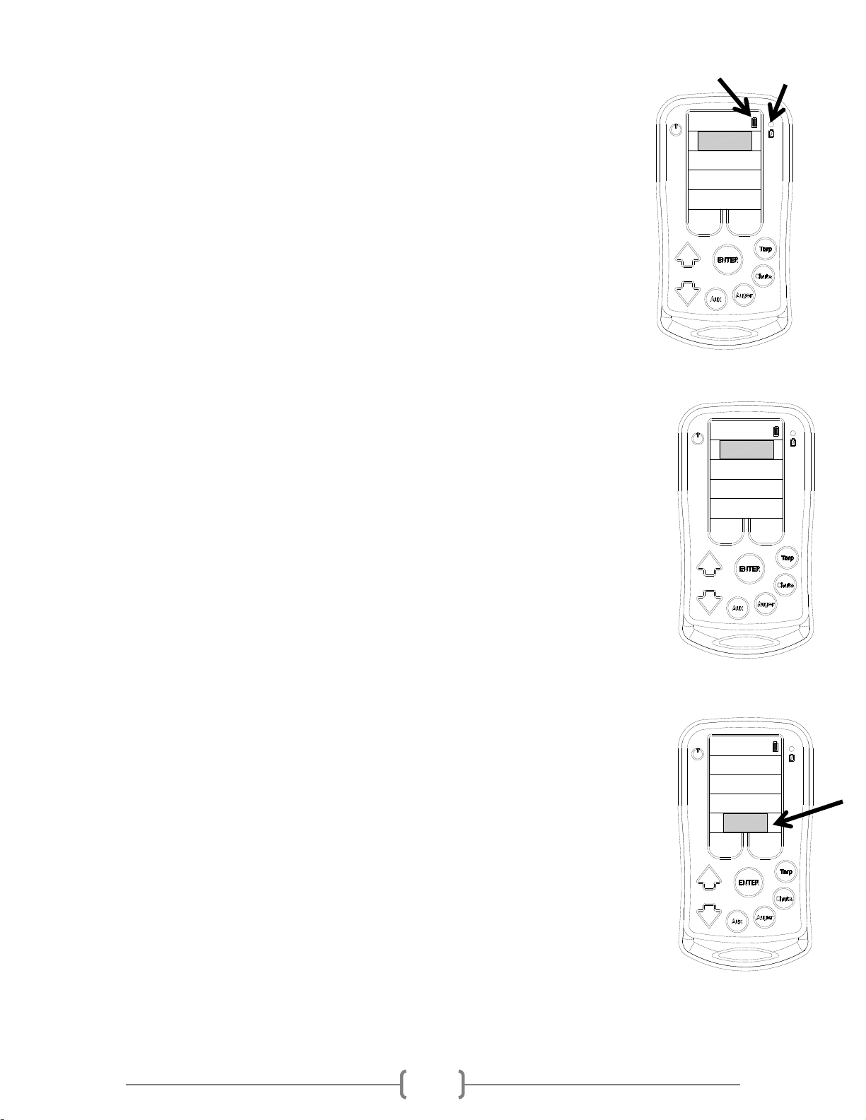
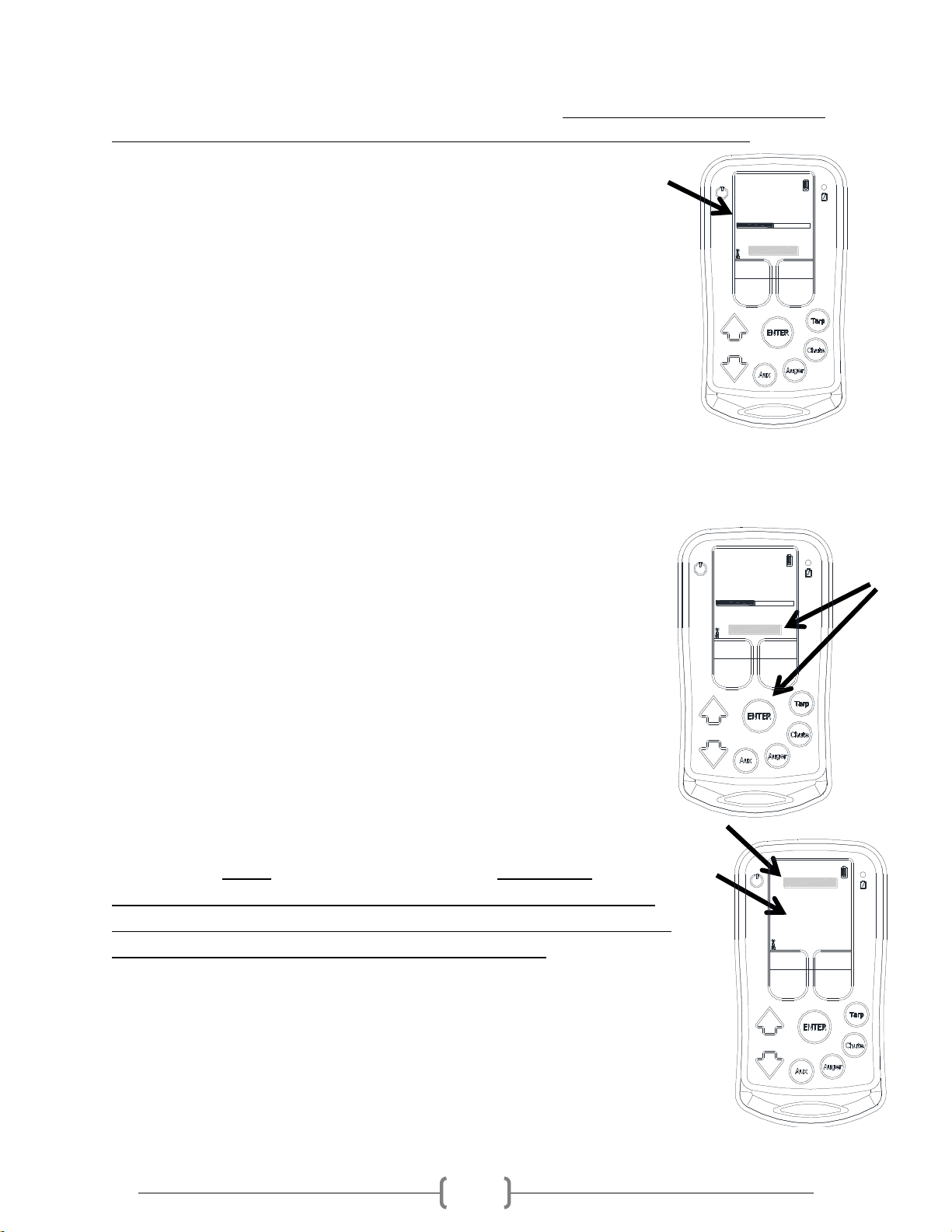
1.1.0 Charging/Battery Indicator
The battery indicator is present on every screen except when ‘Tarps’ is highlighted on
the Home screen. It will show a full, half or empty battery.
The typical life expectancy of the battery is 10 hours of continued use. When the
battery icon starts to flash red there are approximately 10 minutes of on time before
the remote battery will die. It is recommended when the battery indicator shows the
half battery symbol, to charge the remote at your earliest convenience.
While charging the battery, the battery indicator on the screen will show a lightning
bolt inside of the Battery Icon. Only use chargers which have an output of 5.0V and
1.0A. A green and red light will also be illuminated above the Battery Icon on the
right side of the remote. When the battery is fully charged only the green light will illuminate.
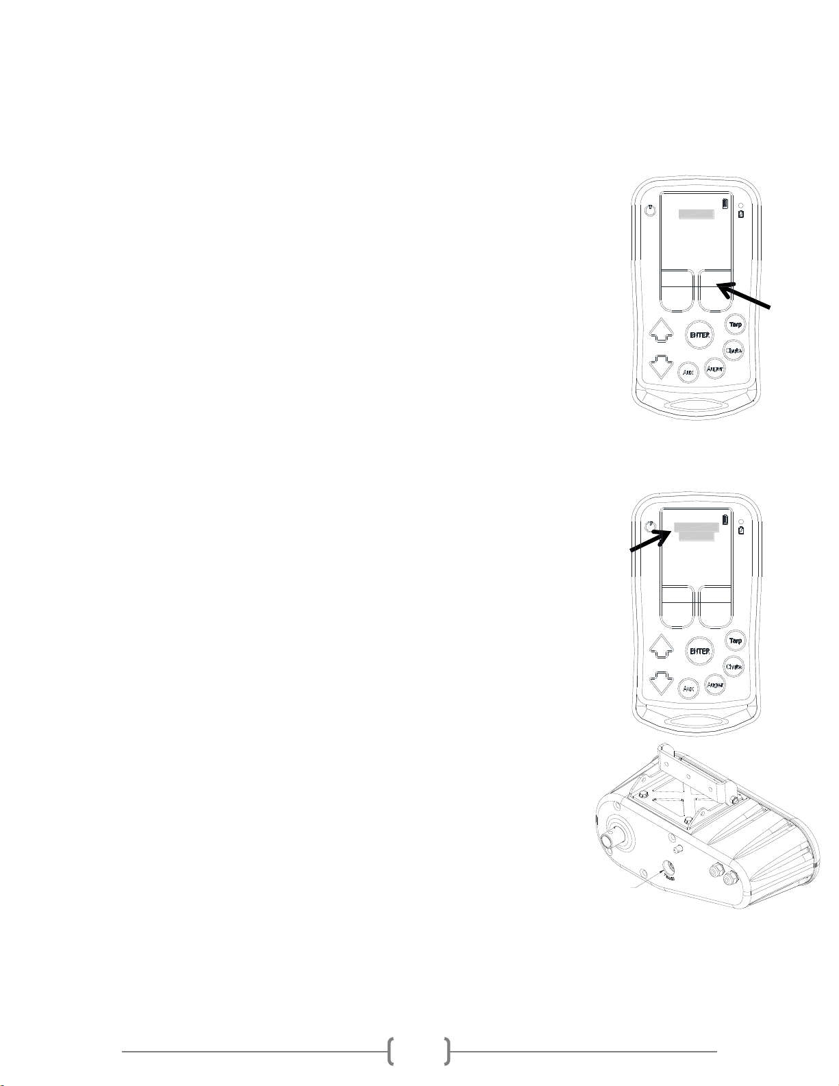
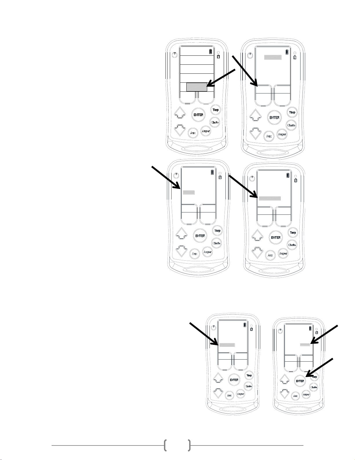
2.0.0 Home Screen
The remote starts on the Home screen once it has been powered on. It will take a
moment after the screen appears to finish loading and allow any user input.
-While in the home screen, scrolling up and down using the arrow keys will allow
access to select Tarps, Chutes, Augers, Auxiliary or Setup. If the remote is not
paired with any receivers (Tarps, Chutes, Augers, or Auxiliaries) it will not enter
into any of the menus.
-Another way to enter into any of the Tarps, Chutes, Augers, or Auxiliaries which
are paired to the remote is by simply pressing the corresponding function key.
-The battery symbol in the top right corner appears on most screens and
indicates the battery level.
3.0.0 Setup Menu
The setup menu can be used to:
1. Teach the remote to communicate with a Tarp, Chute Opener, and/or Auger
receiver so the remote will control it. When adding multiple Tarps, Chute
Openers, or Auxiliary Augers the remote will add them in the order in which
they are paired to the remote. Ex. If pairing a 2 hopper trailer which has
Chute Openers, teach the front hopper to the remote first and it will be called
Chute 1 and then the back hopper will be paired as Chute 2. Therefore, when
adding devices make sure to add them to the remote in the order in which
you would like them to appear on the remote.
2. Adjust the shutdown time of the remote from 5 to 15 or 30 minutes. The shutdown time is
the time the remote will stay on if no buttons are pushed before automatically shutting off.
This feature conserves the battery if the remote is left on.
TARPS
CHUTES
AUGERS
SETUP
AUXILIARY
TARPS
CHUTES
AUGERS
SETUP
AUXILIARY
TARPS
CHUTES
AUGERS
SETUP
AUXILIARY
15-March-2018
7
3. Changing the network ID allows multiple remotes to be added to the same network. In
order for a Tarp, Chute Opener or Auger receiver to talk to multiple remotes the network ID
must be the same. When the remotes are assembled the network ID’s are different. Even if
the remotes have the same Network ID, they still have to be taught to the each receiver
for them to work. Having different Network ID’s provides more security and limits cross
talking.
4. Find the version of Hardware and Firmware of the remote.
To enter the Setup menu, the remote must be on the Home page. Use the up and
down arrows to move the cursor to select / highlight ‘Setup’and then press Enter.
To return to the Home Screen press the button located under ‘EXIT’
3.1.0 Adding Units to the Remote
When the remote adds multiple Tarps, Chute Openers, or Augers it will add them in
the order in which they are paired to the remote. Ex. If pairing with a 2 hopper
trailer which has Chute Openers, teach the front hopper to the remote first and it will
be called Chute 1 and then the back hopper will be taught as Chute 2.
If a unit is removed the next unit added will use the first available spot. Ex. If 2 Chute Openers were
paired to the remote, Chute 1 & Chute 2 then Chute 1 is removed, the next Chute Opener added will be
Chute 1 again and not Chute 3.
Note: When adding devices make sure to add them in the order in which you
would like them to appear on the remote.
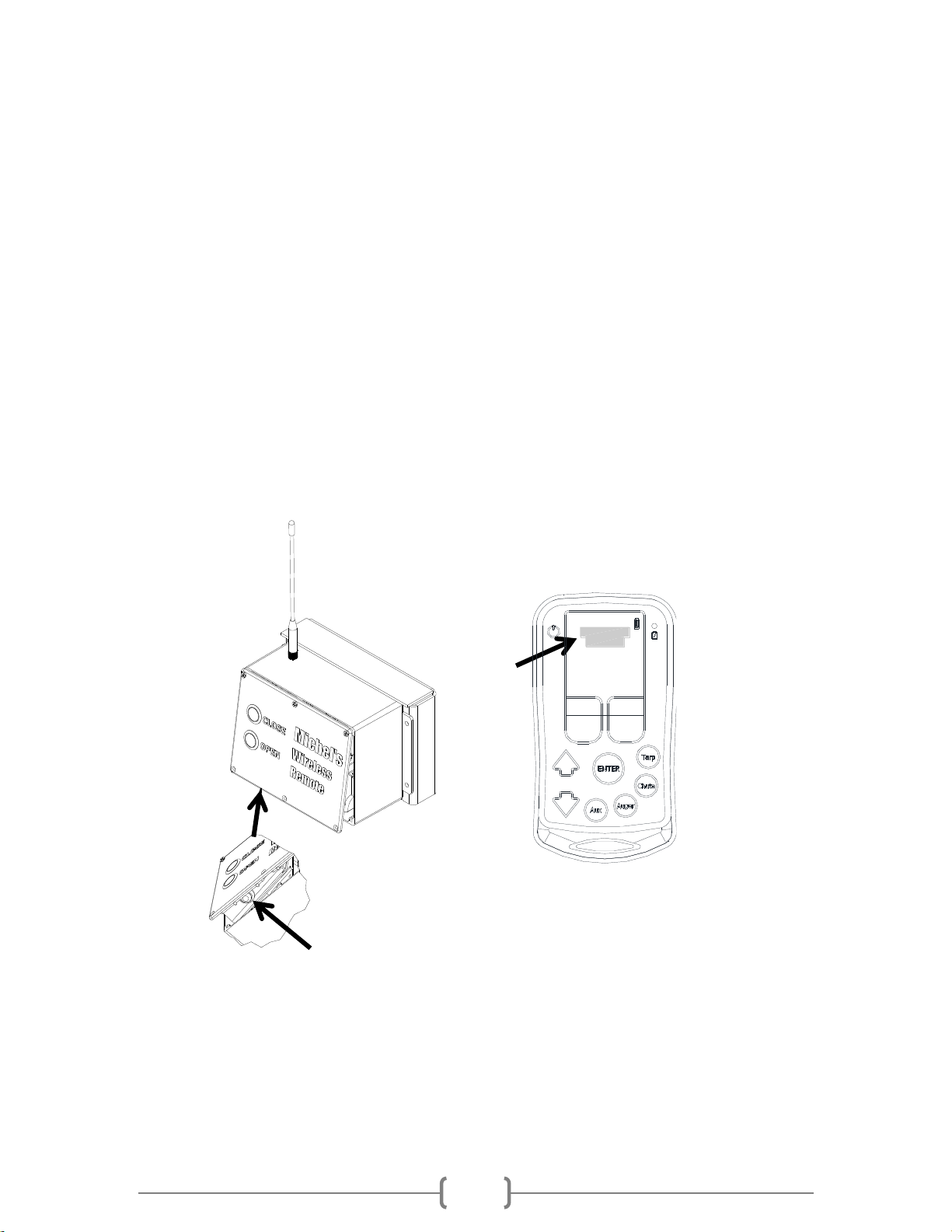
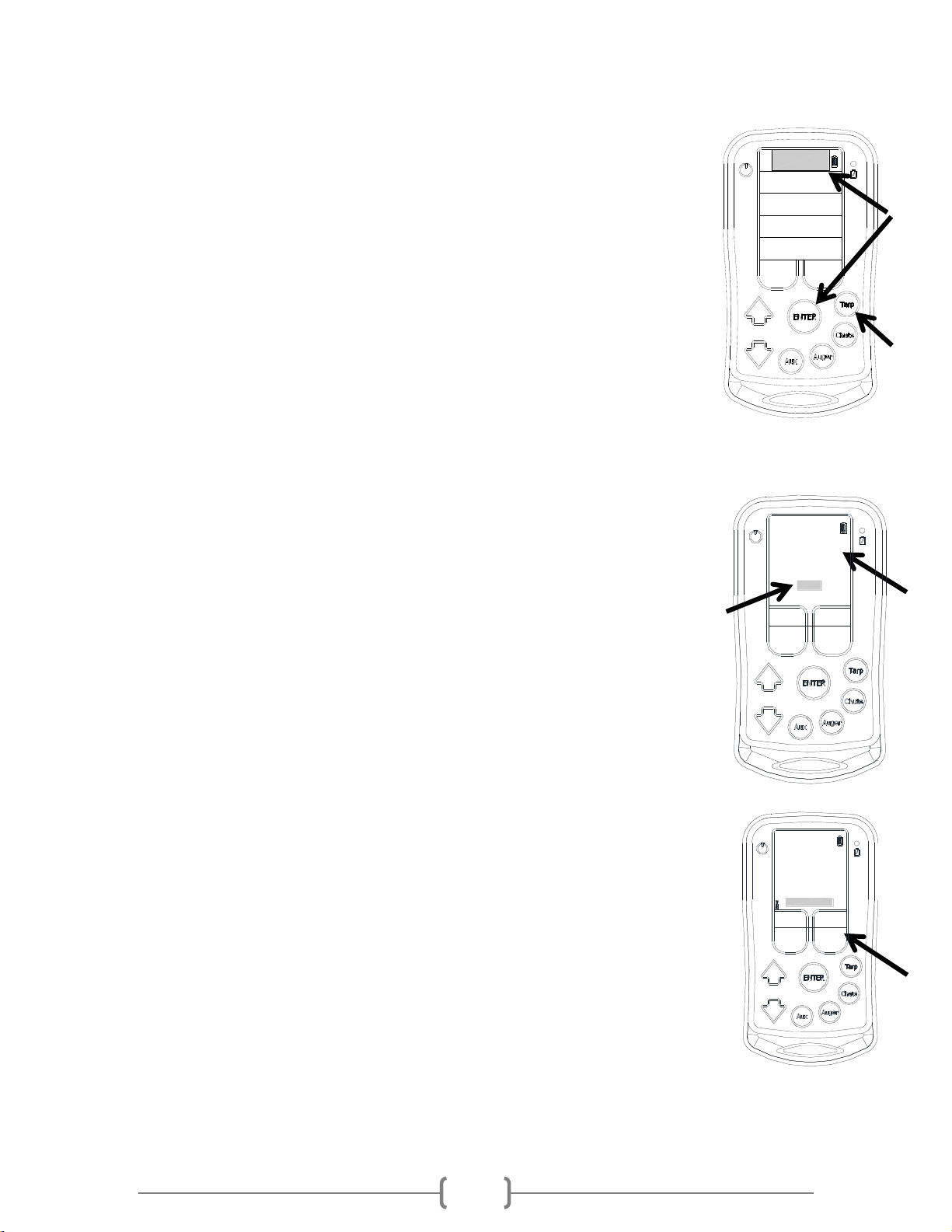
3.1.1 How to add an EZ Opener
Enter into the Setup Menu from the Home Screen. Use the up and down arrows to
move the cursor to select/highlight ‘Setup’and then press Enter.
After entering the Setup menu, make sure ‘ADD UNIT’is highlighted.
Go to the chute opener which is to be programmed. Use a flat screw driver and pop
off the plastic plug on the back side where “Teach” has been embossed around it.
Press and hold the button for at least 7 seconds before pressing Enter on
the remote. The Teach Button on the chute opener must be held on
continuously until the remote is paired. If it is paired properly, it will say
CHUTE 1 ADDED above the add unit line.
Press plastic plug back into the hole in the cover. Press Exit to return to
the home screen.
TEACH BUTTON
SETUP 1
ADD UNIT
15 MIN SHUTDOWN
CHANGE NETWORK ID
68B0
H:0.8.3 F:0.8.2
EXIT
MORE
EDIT SWITCHBOX
SETUP 1
ADD UNIT
15 MIN SHUTDOWN
CHANGE NETWORK ID
68B0
H:0.8.3 F:0.8.2
EXIT
MORE
EDIT SWITCHBOX
CHUTE ADDED

15-March-2018
8
3.1.1.1 How to add an EZ Opener and ‘ConveyHawk’ Conveyor Combination System
If a trailer has both EZ Openers and the wireless ‘ConveyHawk’ Conveyor
system, the ConveyHawk system controls will be connected to and integrated
with the EZ Opener controls. The ConveyHawk will most often be connected to
the front chute opener. The remote will come from the factory with this chute
opener already paired to it. However, the chute opener will require the limits to
be set after it has been taught to the remote, see Section 5.2.1.
The procedure to add the EZ Opener and ‘ConveyHawk’ Conveyor Combination
System to the R200 remote is similar to that of a standalone EZ Opener; see
Section 3.1.1.
Enter into the Setup Menu from the Home Screen. Use the up and down arrows
to move the cursor to select/highlight ‘Setup’and then press Enter.
After entering the Setup menu, make sure ‘ADD UNIT’is
highlighted.
Go to the chute opener which has the connection for the conveyor
built into it. Use a flat screw driver and pop off the plastic plug on
the back side where “Teach” has been embossed around it.
Press and hold the button for at least 7 seconds before pressing
Enter on the remote. The Teach Button on the chute opener must
be held on continuously until the remote is paired. If it is paired properly, it will say GEN UR ADDED
above the add unit line.
Press the plastic plug back into the hole in the cover. Press exit to return to the home screen.
After pairing the chute opener to the remote, two screens will become accessible in the home screen.
The chute screen will now be available. It operates in the same way as a regular chute opener; see
Section 5.0.0 for operating instructions. Also, a conveyor screen under the ‘AUGERS’ menu will become
available; see Section 6.1.1 for operating instructions.
GEN UR ADDED
SETUP 1
H:0.7.0 F:0.9.03
ADD UNIT
15 MIN SHUTDOWN
CHANGE NETWORK ID
MORE
68B0
EXIT
EDIT SWITCHBOX
TEACH BUTTON
15-March-2018
9
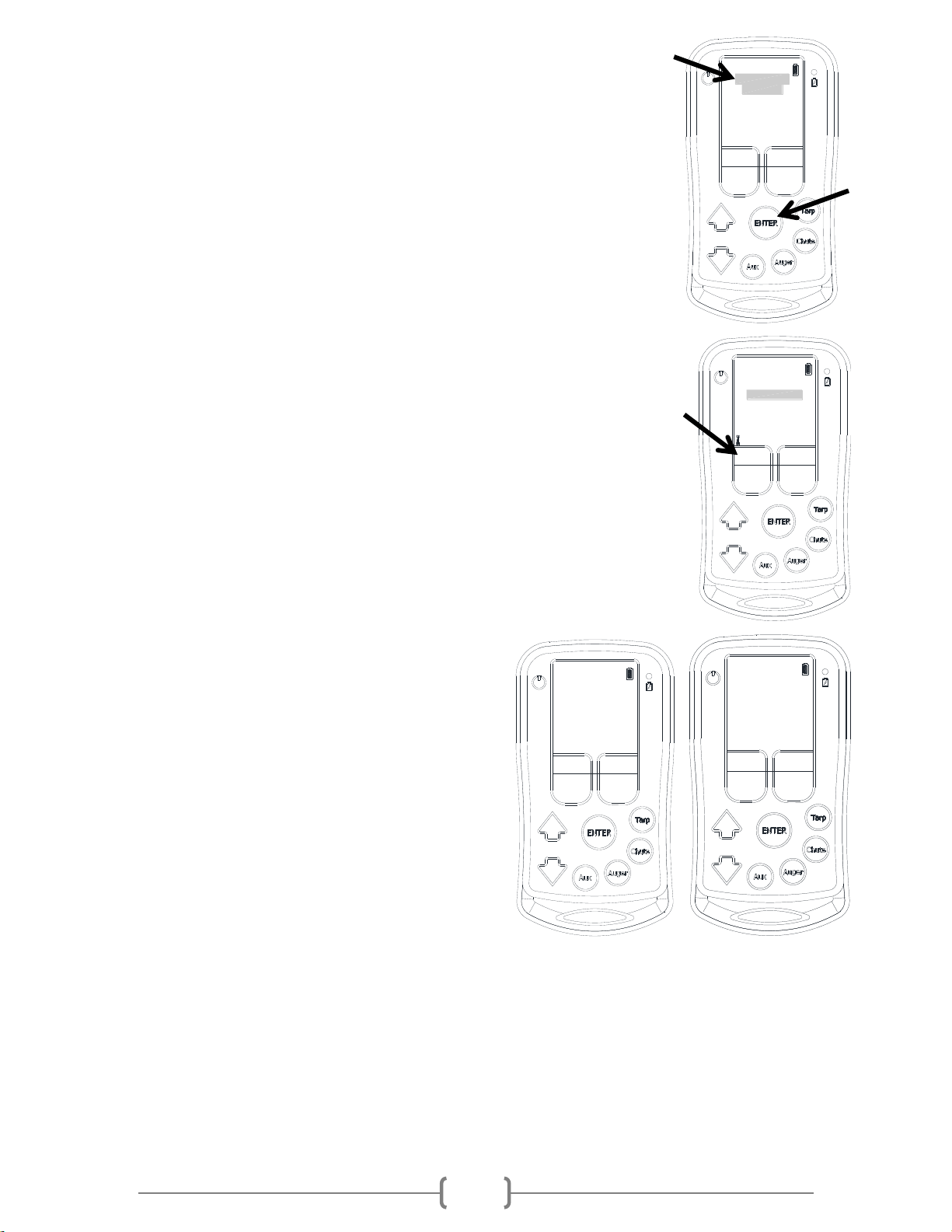
3.1.2 How to add a T200 or T210 Tarp Receiver System
3.1.2.1 How to add a T200 Tarp Receiver
Enter into the Setup Menu from the Home Screen. Use the up and down arrows to move the cursor to
select / highlight Setup and then press Enter.
Upon entering the Setup menu, ADD UNIT should be highlighted.
Go to the T200 Tarp Receiver Box and remove the bottom 3 screws completely from the enclosure.
Loosen the top 3 screws so the lid can be tilted up. It may be necessary to use a flat screw to pop the lid
loose.
With the lid tilted open, press the small black button on the inside of the lid and hold the button for a
minimum of 7 seconds before pressing Enter on the remote. The teach button must be held on
continuously until the remote is paired. If it is paired properly, it will say TARP ADDED above the ‘ADD
UNIT’line.
Secure the lid back onto the T200 control box using the 6 screws.
Press Exit to return to the home screen.
SETUP 1
ADD UNIT
15 MIN SHUTDOWN
CHANGE NETWORK ID
68B0
H:0.8.3 F:0.8.2
EXIT
MORE
EDIT SWITCHBOX
TARP ADDED

15-March-2018
10
3.1.2.2 How to add a T210 Tarp Receiver
Enter into the Setup Menu from the Home Screen. Use the up and down arrows to move the cursor to
select/highlight Setup and then press Enter.
Upon entering the Setup menu, ADD UNIT should be highlighted.
Go to the T210 Tarp Receiver Box. Press and hold the teach button until the red LED illuminates by the
teach button. While still holding the teach button on the T210 Tarp Receiver Box press ENTER on the
remote.
The teach button must be held on continuously until the remote is paired. If the remote is paired to the
T210 Tarp Receiver properly it will say “TARP ADDED” above the add unit line.
Press Exit to return to the home screen.
SETUP 1
ADD UNIT
15 MIN SHUTDOWN
CHANGE NETWORK ID
68B0
H:0.8.3 F:0.8.2
EXIT
MORE
EDIT SWITCHBOX
TARP ADDED

15-March-2018
11
3.1.3 How to add A200 and A210 Auger or Conveyor Receiver Systems
3.1.3.1 How to add an A200 Auger Receiver
Enter into the Setup Menu from the Home Screen. Use the up and down arrows to
move the cursor to select / highlight Setup and then press Enter.
Upon entering the Setup menu, ADD UNIT should be highlighted.
Go to the A200 Auger Receiver Box and completely remove the 4 screws which are
securing the back lid. It may be necessary to use a flat screwdriver to pop the lid
loose.
While the lid is off press the red button on the inside. Hold the button for at least 7
seconds before pressing Enter on the remote. The teach button must be held on
continuously until the remote is paired. If it is paired properly, it will say AUGER
ADDED above ‘ADD UNIT’.
Secure the lid back onto the box with the four screws. Press Exit to return to the home screen.
3.1.3.2 How to add an A210 Auger or Conveyor System
Enter into the Setup Menu from the Home Screen. Use the up and down arrows
to move the cursor to select/highlight Setup and then press Enter.
Upon entering the Setup menu, ADD UNIT should be highlighted.
Go to the A210 Auger/Conveyor Receiver Box. Press and hold the teach button
until the red LED illuminates by the teach button. While still holding the teach
button on the A210 Auger/Conveyor Receiver Box press ENTER on the remote.
The teach button must be held on continuously until the remote is paired. If the
remote is paired to the A210 Auger/Conveyor Receiver properly it will say “AUGER
ADDED” above the add unit line.
Press Exit to return to the home screen.
3.1.4 How to add an S210 Swing Auger Receiver
Enter into the Setup Menu from the Home Screen. Use the up and down arrows to
move the cursor to select/highlight Setup and then press Enter.
Upon entering the Setup menu, ADD UNIT should be highlighted.
Go to the S210 Swing Auger Receiver Box. Press and hold the teach button until the
red LED illuminates by the teach button. While still holding the teach button on the
S210 Swing Auger Receiver Box press ENTER on the remote.
The teach button must be held on continuously until the remote is paired. If the
remote is paired to the S210 Swing Auger Receiver properly it will say “SWING
ADDED” above the add unit line.
SETUP 1
ADD UNIT
15 MIN SHUTDOWN
CHANGE NETWORK ID
68B0
H:0.8.3 F:0.8.2
EXIT
MORE
EDIT SWITCHBOX
AUGER ADDED
SETUP 1
ADD UNIT
15 MIN SHUTDOWN
CHANGE NETWORK ID
68B0
H:0.8.3 F:0.8.2
EXIT
MORE
EDIT SWITCHBOX
SWING ADDED
15-March-2018
12
Press Exit to return to the home screen. See Section 7.5.0 for further instruction
on the Swing Auger.
3.1.5 How to add a MIC210 Side Chute System
Enter into the Setup Menu from the Home Screen. Use the up and down arrows
to move the cursor to select/highlight Setup and then press Enter.
Upon entering the Setup menu, ADD UNIT should be highlighted.
Go to the MIC210 Side Chute Control Box. Press and hold the teach button for
at least 10 seconds. While still holding the teach button on the MIC210 Side
Chute Control Box press ENTER on the remote.
The teach button must be held continuously until the remote is paired. If the
remote is paired to the MIC210 Side Chute Control Box properly it will say “GEN
UR ADDED” above the add unit line.
Press Exit to return to the home screen.
The MIC210 Side Chute Control Box will need to have settings adjusted after it has
been paired to the R200 Remote for it to appear properly in the remote.
Press the ‘Chute’ button on the R200 Remote. Then scroll down to ‘EDIT UNIT’
and press ‘ENTER’.
In the bottom left corner of this screen the option ‘MORE’ will appear. Press the
button below ‘MORE’.
Scroll down to Channel C. Press the button under
‘NEXT’ until ‘act np’ appears. Then scroll down to
Channel D and repeat.
If the unit is a three-hopper unit then repeat again for
channels ‘E’ and ‘F’. If the unit is a two-hopper unit
then presses ‘NEXT’ until ‘none’ appears for both
channels ‘E’ and ‘F’.
After all the channels are set to their appropriate
settings press ‘ENTER’ to save the changes.
There should now be two chute screens for a two
hopper unit or three chute screens for a three hopper unit in the remote.
GEN UR ADDED
SETUP 1
H:0.7.0 F:0.9.03
ADD UNIT
15 MIN SHUTDOWN
CHANGE NETWORK ID
MORE
68B0
EXIT
EDIT SWITCHBOX
EDIT UNIT NAME
ADD REMOVE A CHILD
REMOVE UNIT
CLOSE <=> OPEN
H:1.3.0 F:1.4.9
MORE
EDIT CHUTE
EXIT
Channel D act np
Channel F actnp
EDIT CHUTE
Channel B act np
Channel C act np
Channel E actnp
ENTER to save
Channel A act np
Test
EXIT
EDIT CHUTE
Channel F none
Channel B act np
Channel D act np
Channel A act np
ENTER to save
Channel C act np
Channel E none
Test
EXIT

15-March-2018
13
3.2.0 Changing the Shutdown Time of the Remote
Enter into the Setup Menu from the Home Screen. Use the up and down
arrows to move the cursor to select / highlight Setup and then press Enter.
Use the down arrow and move the cursor over the ‘5 MIN SHUTDOWN’
which could also be 15 or 30 depending what it is set to. It will be highlighted
when the cursor is on it. Press ‘Enter’ and it will cycle through the 3 preset
times: 5, 15 or 30 minutes.
Once the desired time is selected, press ‘Exit’ to return the Home Screen and it
will be saved.
3.3.0 Changing the Network ID
Enter into the Setup Menu from the Home Screen. Use the up and down arrows
to move the cursor to select / highlight Setup and then press Enter.
Use the up or down arrow to move the cursor over ‘CHANGE NETWORK
ID.’ Once it is highlighted press ‘Enter’
The first digit will be highlighted. Use the button located under ‘NEXT’ to scroll
through the options.
Once the desired number is selected, press the ‘Down Arrow’ to go to the next
digit.
Repeat for the next 3 digits using the ‘Next’ button to change the number and
the ‘Down Arrow’ to proceed to the next digit.
Once the last digit is set, press the ‘Enter’ button to save the new Network ID. It will exit to the Home
Screen.
3.4.0 Fleet and B-Train Grouping
The Fleet Grouping feature allows the user to quickly select different trailers on one remote. This
feature allows the user to display only the units for the selected trailer. End-users with multiple trailers
and operators who require B-Train trailers to be split can benefit from the fleet grouping feature on the
remote. No more switching remotes among drivers required. This feature allows one remote to
conveniently operate Michel’s Wireless Technology on several different trailers, allowing the remote to
be left with the truck when switching trailers.
3.4.1 Setting up Groups
The first step to setting the remote up for fleet groups is to teach all of the Michel’s Wireless Technology
on all of the trailers to the remote. For further instruction on pairing Michel’s Wireless Technology see
the appropriate sub-section in Section 3 for the unit to be paired with the remote. Make sure the units
are added to the remote in a logical order. Multiple remotes can be used especially in the case of
multiple drivers; ensure the Network ID is the same on all of the remotes. See Section 3.3.0.
SETUP 1
15 MIN SHUTDOWN
CHANGE NETWORK ID
8B0
H:0.8.3 F:0.8.2
EXIT
ADD UNIT
6
EDIT SWITCHBOX
MORE
EDIT SWITCHBOX
NEXT
6
15 MIN SHUTDOWN
ADD UNIT
CHANGE NETWORK ID
8B0
EXIT
H:0.7.0 F:0.9.03
SETUP 1
15-March-2018
14
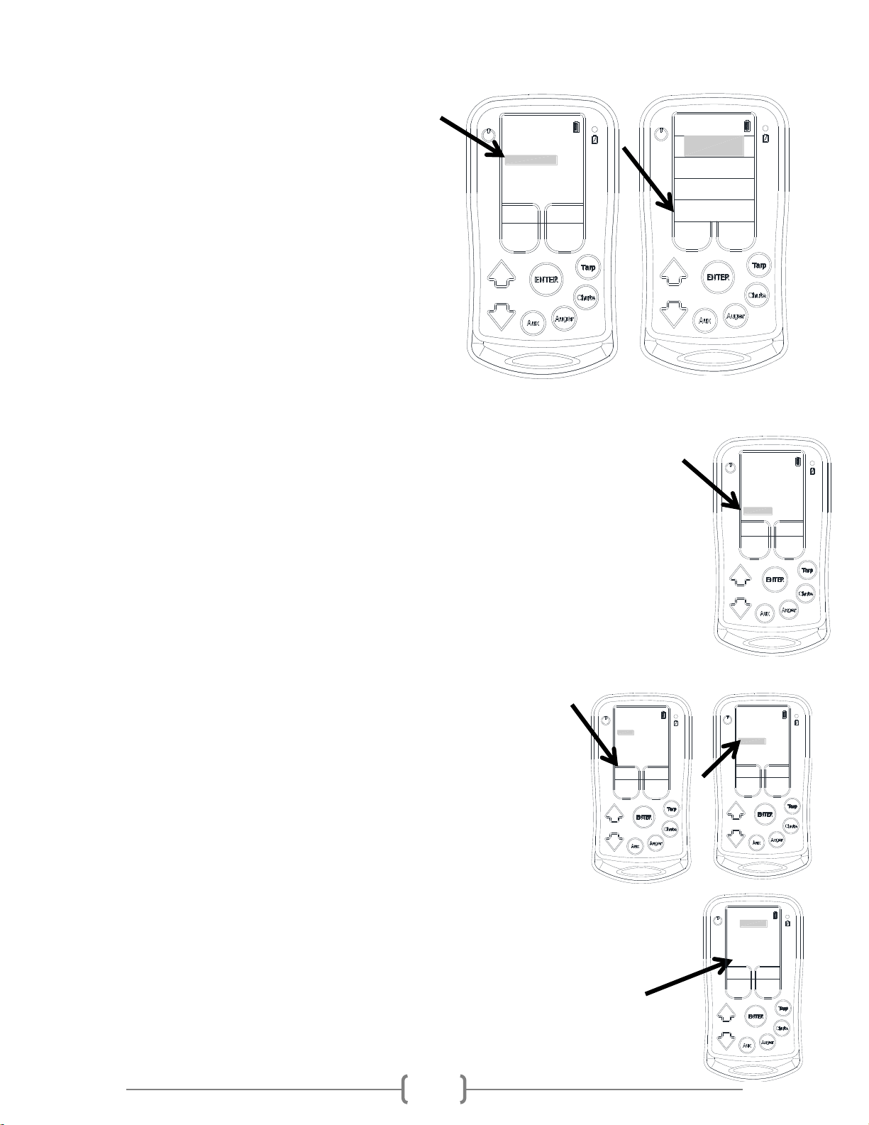
3.4.2 Accessing the Groups Sub-Menu
After all of the units are paired with the
remote. The ‘GROUPS’ sub-menu can be
accessed by highlighting ‘SETUP’ on the
home screen and pressing ‘ENTER’. This will
bring up the ‘SETUP 1’ screen. In the ‘SETUP
1’ screen press the button under ‘MORE’, this
will bring up the ‘SETUP 2’ screen. In this
screen scroll down to ‘GROUPS’ and press
‘ENTER’.
This will bring up the ‘GROUPS’ menu and is
the location where the groups can be
created, edited, selected, or removed.
A shortcut to get to the grouping menu can
be created to minimize the number of
required button presses to switch
groups. From the home screen scroll
down to ‘SETUP’ and press ‘ENTER’.
This will bring up the ‘SETUP 1’ menu. Press
the button under ‘MORE’. This will bring up
the ‘SETUP 2’ Menu. Scroll down to the line
that reads ‘NO SETUP SUBMENU’ and press
‘ENTER’. This will change the line to read
‘SETUP SUBMENU’. Return to the home
screen by pressing ‘BACK’ and then ‘EXIT’.
Now, when the setup stripe on the home
screen is selected, it will bring up a sub-menu
where set up and groups can be selected. Using this menu can save the user a few keystrokes making
the selection of groups quicker.
3.4.3 Creating a New Group
Create a new group by scrolling down to ‘NEW
GROUP’ and pressing ‘ENTER’. In this menu there will
be two columns. The column on the right contains all
of the units which have been paired to the remote and are
available for assignment to a group. One at a time, highlight
the units which will make up the group and press ‘ENTER’. As
you select the units they will begin to appear in the left
column. All the units contained in the left column are part of
the group that is being created. Units can only be assigned to
one group. Once the group has all of the desired units
included on it press the button under ‘DONE’. Then press the
button under ‘SAVE’ to save the group.
TARPS
CHUTES
AUGERS
SETUP
AUXILIARY
MORE
EDIT SWITCHBOX
SETUP 1
ADD UNIT
15 MIN SHUTDOWN
CHANGE NETWORK ID
68B0
H:0.7.0 F:1.1.15
EXIT
SETUP 2
NEW LIGHTS SCREEN
TECH
NO AUX FEATURE
ACCESS LIGHT UNIT
EDIT GEN UR
TESTS
GROUPS
SETUP SUBMENU
BACK
SETUP 2
NEW LIGHTS SCREEN
TECH
NO AUX FEATURE
ACCESS LIGHT UNIT
EDIT GEN UR
TESTS
GROUPS
SETUP SUBMENU
BACK
GROUPS
NO GROUP
EXIT
GROUP TO EDIT:
CURRENT GROUP
EDIT GROUP
REMOVE GROUP
NEW GROUP
EDIT NAME
BACK
DONE
unnamed group
UNITS
TARP 1 TARP 1
CHUTE 1 TARP 2
<<<
CHUTE 1
CHUTE 2
CHUTE 3
CHUTE 4
CHUTE 2
GROUP 2
GROUP
15-March-2018
15
3.4.4 Selecting a Group
Highlight ‘GROUP TO EDIT:’ and press ‘ENTER’. This will
scroll through all of the different groups on the
remote. If any group remains unnamed it is
recommended to give that group a unique
descriptive name. See Section 3.4.5. There is a group
counter that indicates which number the group is in
the group series to differentiate the groups if none of
the groups have been named yet. Then scroll down to
‘MAKE CURRENT’ and press ‘ENTER’. The group will be
selected and the home screen will appear. This will
make the group current and only the units associated
with that group will be displayed. If the line says
‘CURRENT GROUP’ and is grey that means this group
has already been selected as the current group. The
default is ‘NO GROUP’. When ‘NO GROUP’ is displayed then all of the units paired with the remote will
be displayed. If there is a group selected the group name will appear on the setup stripe of
the home screen below ‘SETUP’ to indicate which group is active. If ‘NO GROUP’ is
selected then there will not be any group indicators on the setup stripe of the home
screen.
3.4.5 Changing the Group Name
Select the group which is to have its name edited. See Section 3.4.4. Rename the group by
scrolling down to ‘EDIT NAME’ and pressing ‘ENTER’. Use the ‘NEXT’and ‘PREV’buttons to
select the desired character. Then press the down arrow to move to the next character. Press
enter to save the name. Press the up arrow button to abort the name change without saving
any of the changes.
3.4.6 Editing an Existing Group
Select the group to be edited. Scroll down to ‘EDIT GROUP’ and press
‘ENTER’. To remove units from the group press the white button under
the arrows to switch columns. Highlight the unit to be removed and
press ‘ENTER’. It will no longer appear in the left column. If a new unit
is required in the group, follow the same procedure as in Section 3.4.3.
Once the group has all of the desired units included on it press the button
under ‘DONE’. Then press the button under ‘SAVE’ and this will save the
group. Press ‘EXIT’ to return to the ‘GROUPS’ menu.
3.5.0 Locating the Hardware and Firmware Version
Enter into the Setup Menu from the Home Screen. Use the up and down arrows to move the
cursor to select / highlight Setup and then press Enter.
The bottom line of the setup menu states the hardware and firmware version of
the remote. For the diagram the hardware version is 0.7.0 and firmware 0.9.03.
MORE
EDIT SWITCHBOX
H:0.7.0 F:0.9.03
EXIT
SETUP 1
15 MIN SHUTDOWN
CHANGE NETWORK ID
68B0
ADD UNIT
GROUPS
0 TRAILER 1
EXIT
GROUP TO EDIT:
MAKE CURRENT
EDIT GROUP
REMOVE GROUP
NEW GROUP
EDIT NAME
BACK
AUXILIARY
SETUP
TRAILER1
TARPS
AUGERS
CHUTES
GROUPS
0 TRAILER 1
EXIT
GROUP TO EDIT:
MAKE CURRENT
EDIT GROUP
REMOVE GROUP
NEW GROUP
EDIT NAME
BACK
EXIT
GROUP TO EDIT:
MAKE CURRENT
EDIT GROUP
REMOVE GROUP
NEW GROUP
EDIT NAME
BACK
GROUPS
0 TRAILER 1
CHUTE 2
GROUP 2
GROUP
DONE
unnamed group
UNITS
TARP 1 TARP 1
CHUTE 1 TARP 2
<<<
CHUTE 1
CHUTE 2
CHUTE 3
CHUTE 4
15-March-2018
16
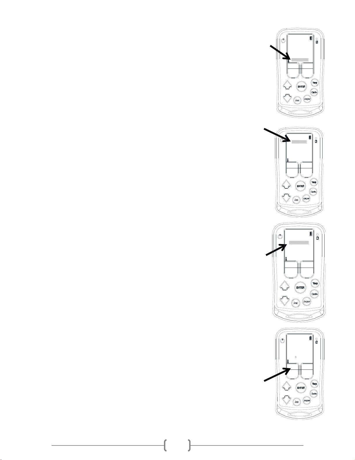
4.0.0 Tarp Menu
To enter into the Tarp Menu, simply press the ‘Tarp’ function button on the side of
the remote or select ‘TARPS’ from the Home Screen.
If there is no tarp receivers paired to the remote, it will not allow access into the Tarp
Menu.
The remote will open the first tarp that was paired to the remote, as TARP 1. From
this menu a person will be able to:
-Open or Close the tarp.
-Edit Unit which will allow changes to the description, reverse the direction of
motor, remove the unit, or find the hardware and firmware version.
-Return to the Home Screen.
-Add/Remove Children to the tarp box
Repeatedly pressing the ‘TARP’ function button will scroll through all the tarps which have been paired
to the remote.
After entering the Tarp menu it will show whether or not there is communication with
the tarp receiver by stating ‘Motor Off’ and by displaying an antenna symbol in the
bottom left of the screen. If ‘No Answer’ is displayed and an antenna symbol does
not appear on the screen the possible problems are: receiver is out of range, the tarp
receiver is not powered on, or the wrong tarp selected.
If the remote has connected to the receiver and is then moved out of range, the screen
will continue to say ‘Motor Off’ even if the ‘Open’ and ‘Close’ buttons are pressed.
4.1.0 Operating the Tarp
Enter into the Tarp Menu by using the ‘TARP’ function button on the side of the remote
or selecting ‘TARPS’ from the Home Screen.
If the desired tarp is not ‘TARP 1’ keep pressing the ‘TARP’ button to cycle through the
different tarps.
Once on the correct Tarp screen, press one of the operating buttons under the ‘Close’ or
‘Open’ on the screen to operate the motor.
If the direction of the motor is backwards to the remote, see 4.2.2 Reversing Motor
Direction.
AUGERS
TARPS
AUXILIARY
SETUP
CHUTES
TARP 1
NO ANSWER
HOME
00 40 B2 C2 78
OPENCLOSE
EDIT UNIT
TARP 1
MOTOR OFF
HOME
EDIT UNIT
00 40 B2 C2 78
OPENCLOSE
15-March-2018
17
EDIT TARP
REMOVE UNIT
PREV
CLOSE <=> OPEN
EDIT UNIT NAME
H:0.8.3 F:0.8.2
ADD REMOVE A CHILD
NEXT
0000000
Z
4.2.0 Tarp Edit Menu
To get into the ‘Tarp Edit Unit’ Menu, enter into the Tarp Menu by using the ‘TARP’
function button on the side of the remote or selecting ‘TARPS’ from the Home Screen.
Use the up or down arrow to select / highlight ‘Edit Unit’ and press ‘Enter’.
Once in the ‘TARP’ menu it will be possible to remove a tarp receiver, change motor
direction, edit the description, find the hardware and firmware version, or add and
remove children from the Tarp Box. Section 7.4.0 further discusses adding and removing
children to the Tarp Box.
4.2.1 Removing a Tarp Receiver
It is possible to remove receivers that have been paired to the remote.
Enter the ‘Edit Unit’ menu. ‘Remove Unit’ should be highlighted. Press ‘Enter’ to
remove the unit. The remote screen will ask for verification that the tarp receiver is to
be removed.
Press the operating button under ‘Yes’ to completely remove it. It is possible to re-add
a Tarp Receiver that has been removed from the remote.
4.2.2 Reversing Motor Direction
When the remote is paired to an electric tarp system the ‘Open’ and ‘Close’ buttons
may be backwards. Simply change the direction using the remote without switching
any wires.
Enter the ‘Edit Unit’ menu of the Tarp which needs its direction changed.
Use the up and down arrows and select ‘Close <=> Open’ and press ‘Enter’
The screen will change to ‘Open <=> Close’. The direction of the motor has now been
changed.
Press ‘Exit’ to return to the Tarp Screen.
4.2.3 Changing the Unit Name
The main name will always be ‘TARP 1’ or 2 or 3 etc. but the description below it can be
customized to represent a trailer or location. The new name can be a maximum of 8
characters long.
Enter into the ‘Edit Unit’ menu of the Tarp to change the name.
Use the up and down arrows to select ‘Edit Unit Name’ and press ‘Enter’.A box will
appear around the first letter on the left side of the screen. Use the ‘Next’ and ‘Prev’ to
scroll through the characters. The available characters include 0-9, the alphabet, and a
ADD REMOVE A CHILD
MORE
EDIT TARP
REMOVE UNIT
EXIT
CLOSE <=> OPEN
EDIT UNIT NAME
H:0.8.3 F:0.8.2
ADD REMOVE A CHILD
MORE
EDIT TARP
REMOVE UNIT
EXIT
CLOSE <=> OPEN
EDIT UNIT NAME
H:0.8.3 F:0.8.2
TARP 1
MOTOR OFF
HOME
EDIT UNIT
00 40 B2 C2 78
OPENCLOSE

15-March-2018
18
blank space.
Once the correct character has been set, press the down arrow to advance to
the next character.
When finished, press ‘Enter’ to save the changes.
Press ‘Exit’ to return to the Tarp screen. The new name will appear below
‘TARP 1’.
4.2.4 Locating the Hardware and Firmware Version
Enter into the ‘Edit Unit’ menu of the desired Tarp to find the version of
hardware and firmware.
The bottom line of the ‘Edit Unit’ states the hardware and firmware version.
For the diagram the hardware version is 0.8.3 and firmware 0.8.2.
5.0.0 Chute Opener Menu
To enter the Chute Opener menu, simply press the ‘Chute’ function button on
the side of the remote or select ‘CHUTES’ from the Home Screen.
If there are no Chute Openers paired to the remote, it will not allow access into
the Chute Menu.
The remote will go to the first chute which was paired to the remote, as CHUTE 1.
From this menu a person will be able to:
-Open or Close the chute.
-Edit Unit which will allow the limits to be set, change unit name, remove
a Chute Opener and, find the hardware and firmware version.
-Return to the Home Screen.
Repeatedly pressing the ‘CHUTE’ function button will scroll through all of the
chute openers which have been paired to the remote.
When entering the Chute menu, the screen will show whether or not the
remote is connected to the Chute Opener by displaying a percentage from
0-100 and an antenna symbol in the bottom left of the screen. If there is a
sad face ‘’ and the antenna symbol does not appear the possible problems are:
receiver is out of range, the chute receiver is not powered on, or the wrong chute
selected.
While using the remote if it becomes out of range the percentage reading will
stop moving while the ‘Open’ or ‘Close’ buttons are being pressed on the remote.
TARPS
AUGERS
CHUTES
AUXILIARY
SETUP
ADD REMOVE A CHILD
MORE
EDIT TARP
REMOVE UNIT
EXIT
CLOSE <=> OPEN
EDIT UNIT NAME
H:0.8.3 F:0.8.2
CHUTE 1
EDIT UNIT
00 40 B2 C0 D0
% OPEN
HOME
OPENCLOSE
15-March-2018
19
5.1.0 Operating an EZ Opener Chute Opener
The limits need to be set on the remote the first time it is used. It may let the chute opener move but
damage to the chute opener and/or the trailer may occur if the limits are not properly set. Please
refer to 5.2.1 Setting the Limits of the Chute Opener.
Enter into the Chute Menu by using the ‘CHUTE’ function button on the side
of the remote or selecting ‘CHUTES’ from the Home Screen.
If the desired chute opener is not ‘CHUTE 1’ continue pressing ‘CHUTE’ to cycle
through all of the chute openers which have been paired to the remote.
Once on the correct Chute screen is selected, press either of the operating
buttons under the ‘Close’ or ‘Open’. If the limits are set properly, the chute will
automatically stop when the chute is completely open or closed. The percentage
indicated shows precisely how far open the chute currently sits.
While closing the chute, if the ‘Close’ button is held for longer than 2 seconds it
will automatically close all the way, even if the button is released.
If the chute opener is equipped with lights see Section 7.2.0 for instructions on
operating the lights.
5.2.0 EZ Opener Chute Opener Edit Menu
To get into the chute ‘Edit Unit’ menu, enter into the Chute Menu by using the
‘CHUTE’ function button on the side of the remote or by selecting ‘CHUTES’
from the Home Screen. Scrolling to the required Chute Opener may be
required to get to the desired chute opener screen. Then use the down arrow
to select/highlight ‘Edit Unit’ and press ‘Enter’.
From there the limits will be able to be set, unit name can be changed,
removal of a Chute Opener and the hardware and firmware version found.
5.2.1 Setting the Limits of the EZ Opener Chute Opener
***Prior to setting the limits the chute opener may run backwards
(open button may close, close button may open). This will be corrected
automatically AFTER the limits have been set.*** It is strongly
recommended to NOT press the open or close buttons until AFTER the
limits have been set! Failure to heed this warning may result in a broken
position sensor and will not be covered under warranty.
Setting the limits will automatically stop the chute opener when it reaches the fully
opened or closed position. When the Chute Opener is installed make sure the chute is
moved to the halfway open position before securing the crank shaft to the opener. If
the chute opener will not completely open or completely close AFTER the limits have
been set see section 5.2.1.1 or phone Michel’s Industries for assistance (306-366-
2184).
CHUTE 1
EDIT UNIT
00 40 B2 C0 D0
% OPEN
HOME
CLOSE
50
OPEN
CHUTE 1
EDIT UNIT
00 40 B2 C0 D0
% OPEN
HOME
CLOSE
50
OPEN
EDIT CHUTE
SET CLOSE LIMIT
DIR2
H:0.8.3 F:0.8.2
SAVE LIMITS
DIR1
SET OPEN LIMIT
ABORT = UP
POS: 2050/4096
Table of contents


