VERIFICATION
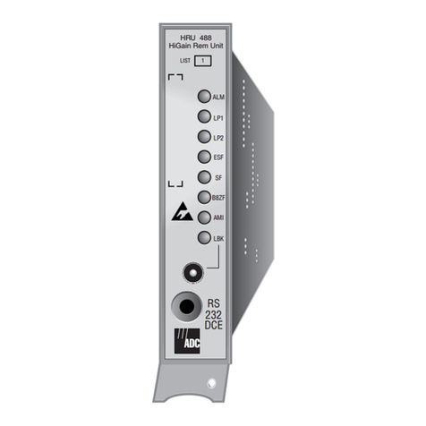
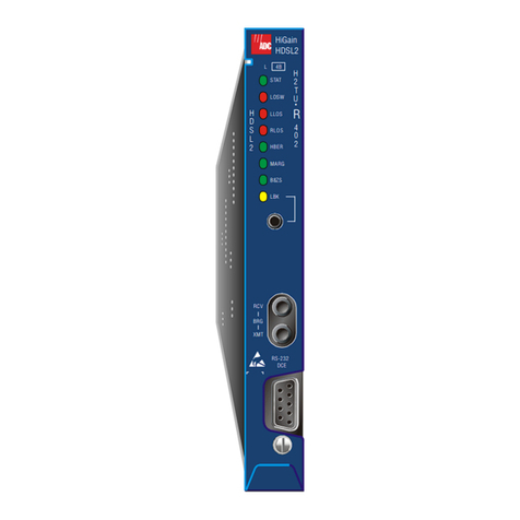
Once the HRU is installed, verify that it is operating properly by monitoring the status
LEDs on the front panel.
LOGGING ON TO THE MAIN MENU
The HRU supports remote login through a maintenance terminal (ASCII terminal or a PC
running terminal emulation software) connected to the craft port on the HRU front panel.
Remote login creates menus and screens for the HRU that are identical to those viewed at
the HLU. Once logged on, access the Remote Terminal Main Menu screens to view system
settings, initiate loopbacks, and provision the circuit.
To log on and access the Remote Terminal Main Menu screens using a maintenance
terminal:
1Press the several times to display the Remote Login screen.
2Press the key to view the HiGain Maintenance Terminal Screen.
The Remote Terminal Main Menu items are replications of the line unit screens.
Depending on the HLU attached to the HRU-402, remote provisioning may be
available. Refer to the appropriate HLU user manual for details.
LOOPBACK TESTING
Initiate loopback testing from the HiGain maintenance menus or by using inband codes.
The inband codes shown below can be sent by a test set.
DS1 transmit and receive monitor jacks
Craft port provisioning
To access all system maintenance, provisioning
and performance screens, connect a standard
9-pin terminal cable between the serial port on a PC
and the HRU craft port.
DS1 receive level switch
This switch sets the receive line buildout output
toward the Customer Interface (CI)
Loopback control button
Pressing the button for 5 seconds activates
a remote loopback towards the network, called a
Network Remote Loopback (NREM).
The unit can be looped down by
either pressing the LPBK control button again
for 5 seconds or by the standard loopdown inband
messages.
Any
existing loopback is terminated before NREM
is activated.
Modem settings:
1200-9600 baud
8 data bits
No parity
1 stop bit
Hardware flow control:OFF
Terminal emulation:VT-100
27
25
23
21
19
17
15
13
11
9
7
3
5
1
DS-1 Tip
Card-edgeConnector
DS-1 Ring
HDSL2 Ring1
HDSL2 Tip1
Factory Use Only
Factory Use Only
Factory Use Only
Protection Switch Power
DS-1 Ring1
Circuit Ground
(-)
(+)
HDSL1 Ring
XMT
RCV
HDSL1 Tip
DS-1 Tip1
Chassis Ground*
28
26
24
22
20
18
16
14
12
10
8
4
6
2
55
53
51
49
47
45
43
41
39
37
35
32 31
56
54
52
50
48
46
44
42
40
38
36
34
30
33
29
Note: Active pins are highlighted in black.
*Chassis Ground may be tied to earth ground per local practice.
-48Vdc Local Power
Protection Switch Control
Chassis Ground*
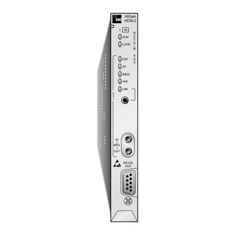
Alarm LED
Loopback LED
TLOS loopback switch
CLEI/ECI Bar code label
Extraction handle
Configuration number label
(inside handle)
HDSL LEDs
DS1 framing LEDs
DS1 code LEDs
ALM
L
TELEPHONE Co. PROPERTY
LP2
ESF
SF
LP1
B8ZS
AMI
LBK
H
D
S
L
RCV
LEV
D
S
1
0-15
DIS EN
TLOS
LB
XMT
MON
RCV
RS-232
DCE
List number
0
-15
Sets the DS1 receive level toward the
CI to 0 dB.(Default setting)
Sets the DS1 receive level toward the CI
to -15 dB.
Enables (ENA) or disables (DIS)
the TLOS loopback option
For monitoring and test access.
(List 2 only)
REM UNIT
HiGain
HRU-402
Status LED Descriptions
LED Status Indicates
Alarm (ALM) LED Shows alarm states for remote and local Loss of Signal (LOS).
Solid red Indicates a LOS condition at the HRU-402 T1 input.
Blinking Indicates a LOS condition at the HLU T1 input.
HDSL LED Displays HDSL Loop 1 and Loop 2 conditions.
Solid green Indicates HDSL Loop 1 and Loop 2 are in sync.
Blinking once
per second Indicates the HDSL loop is trying to acquire sync.
Blinking 4 times
per second Indicates a margin alarm condition on the HDSL loop.
Blinking 10 times
per second Indicates a Cyclical Redundancy Check (CRC) error on the HDSL loop.
OFF Indicates no activity on the HDSL loop.
DS1 Framing (FRM)
LEDs (ESF and SF) Indications for framing patterns. If DS1 signals are not detected, the ESF, SF,
B8ZS, and AMI LEDs will not light.
ESF LED = Solid green Indicates Extended Super Frame (ESF). The LED blinks once per second when a
frame error is indicated.
SF LED = Solid green Indicates Super Frame (SF). The LED blinks twice per second when a frame error
is indicated.
OFF Indicates unframed or no signal.
DS1 Code LEDs
(B8ZS and AMI) Indications for DS1 code options. If DS1 signals are not detected, the ESF, SF,
B8ZS, and AMI LEDs will not light.
B8ZS LED = Solid green Indicates that the DS1 linecode option is set to Bipolar with 8-Zero Substitution
(B8ZS). The LED blinks once per second when a string of excessive zeros is
detected.
AMI LED = Solid green Indicates that the user DS1 line code option is set to Alternate Mark Inversion
(AMI). This LED blinks once per second when a Bipolar Violation (BPV) is
detected.
Loopback (LPBK) LED Shows loopback states to and from the network and to and from the Customer
Interface (CI).
Solid yellow Indicates Network Remote Loopback (NREM), SmartJack (SMJK), or Transmit
Loss of Signal (TLOS).
Blinking once
per second Indicates Customer Local Loopback (CLOC) loopback state.
Blinking 4 times per
second Indicates the HRU is in an Armed state.
For more detailed information about the Maintenance Terminal
screens, provisioning and loopback mode testing, download the
appropriate line unit user manual from the Customer Site portion of
the ADC Web page at www.adc.com.
SPACEBAR
ENTER
Table 1. Remote Terminal Main Menu Items
Menu Item Function
View Span Status Allows viewing of span status from the HLU to the HRU-402 (non-doubler
applications) and from any doubler spans (multi-span applications).
Set Clock Allows setting of time and date parameters at the HRU.(a)
(a) If the HLU does not have remote provisioning or its remote provisioning option is disabled, the HRU
cannot modify these settings.
System Settings Allows viewing and setting of all system settings.(a)
Loopback Mode Allows system loopbacks to be initiated.
View Performance Data Allows viewing of the Errored Seconds (ES) and Unavailable Seconds (UAS) for
the HLU to HRU-402 span (non-doubler applications) and any additional spans
(doubler applications) in 15-minute intervals over a 4-hour time period.
View Performance
History Allows viewing of the ES and UAS for the HLU to HRU-402 span (non-doubler
applications) andanyadditional spans(doublerapplications)in 24-hour intervals
over a 31-day period.
View Alarm History Allows viewing of alarm conditions for the HLU to HRU-402 span (non-doubler
applications) and any additional spans (doubler applications).
View System Inventory Displays the model number, serial number, and ID of all units in the circuit.
View Troubleshooting Provides a graphical analysis of the circuit and identifies problem areas.
Remote Logoff Terminates the remote session.
Table 2. GNLB Loopback Commands
Loopback Inband Code Description
NDU1 110000 DSX-1 signal is looped back to the network at HDU1.
NDU2 111000 DSX-1 signal is looped back to the network at HDU2.
NDU3 1010001 DSX-1 signal is looped back to the network at HDU3.
NDU4 1010010 DSX-1 signal is looped back to the network at HDU4.
NREM 1110000 DSX-1 signal is looped back to the network at the HRU.
SMJK 11000 DSX-1 signal is looped back to the network at the HRU SmartJack module.
CLOC 1111100 Signal from customer is looped back to the customer at the HRU.
CDU1 111100 Signal from customer is looped back to the customer at HDU1.
CDU2 111110 Signal from customer is looped back to the customer at HDU2.
CDU3 1011001 Signal from customer is looped back to the customer at HDU3.
CDU4 1011010 Signal from customer is looped back to the customer at HDU4.
CREM 1111110 Signal from customer is looped back to the customer at the HLU.
Loopdown 11100 Deactivates any of the above loopbacks.
Network Customer
Pr
mi
HLU HDU1 HDU2 HRU
NLOC NDU1 NDU2
NREM
SMJK
TLOS
CREM CDU1 CDU4CDU2 CLOC
HDU3 HDU4
NDU3 NDU4
CDU3
