Micrel KSZ8081RNA User manual

Micrel, Inc. 2180 Fortune Drive San Jose, CA 95131 U.S.A.
408-944-0800 (voice) 408-474-1000 (fax)
http://www.Micrel.com
KSZ8081RNA / KSZ8081RND
10Base-T/100Base-TX
Physical Layer Transceiver
Evaluation Board User’s Guide
Revision 1.0 / August 2012
© Micrel, Inc. 2012
All rights reserved
Micrel is a registered trademark of Micrel and its subsidiaries in the
United States and certain other countries. All other trademarks are the
property of their respective owners.
The information furnished by Micrel in this datasheet is believed to be accurate and reliable. However, no responsibility is
assumed by Micrel for its use. Micrel reserves the right to change circuitry and specifications at any time without
notification to the customer. Micrel Products are not designed or authorized for use as components in life support
appliances, devices or systems where malfunction of a product can reasonably be expected to result in personal injury.
Life support devices or systems are devices or systems that (a) are intended for surgical implant into the body or (b)
support or sustain life, and whose failure to perform can be reasonably expected to result in a significant injury to the user.
A Purchaser's use or sale of Micrel Products for use in life support appliances, devices or systems is at Purchaser's own
risk and Purchaser agrees to fully indemnify Micrel for any damages resulting from such use or sale.

KSZ8081RNA / KSZ8081RND 10Base-T/100Base-TX Evaluation Board User’s Guide
Micrel, Inc. August 17, 2012
Rev. 1.0
2/11
Revision History
Revision Date Summary of Changes
1.0 8/17/12 Initial Release

KSZ8081RNA / KSZ8081RND 10Base-T/100Base-TX Evaluation Board User’s Guide
Micrel, Inc. August 17, 2012
Rev. 1.0
3/11
Table of Contents
1.0Introduction ............................................................................. 5
2.0Board Features........................................................................ 5
3.0Evaluation Kit Contents.......................................................... 5
4.0Hardware Description............................................................. 6
4.1RMII (Reduced Media Independent Interface)...................................................... 7
4.2MDC/MDIO Management Interface........................................................................ 9
4.2.1USB Interface ............................................................................................. 9
4.3Power ....................................................................................................................... 9
4.4RMII Loopback Jumpers...................................................................................... 10
4.5Test Point Definition............................................................................................. 11
4.6RJ-45 Connector................................................................................................... 11
4.7LED Indicators ...................................................................................................... 11

KSZ8081RNA / KSZ8081RND 10Base-T/100Base-TX Evaluation Board User’s Guide
Micrel, Inc. August 17, 2012
Rev. 1.0
4/11
List of Figures
Figure 1. KSZ8081RNA / KSZ8081RND Evaluation Board ........................................................... 6
Figure 2. KSZ8081RNA-EVAL interfacing with KSZ8463RLI Evaluation Board............................ 7
List of Tables
Table 1. Board Configuration for RMII Clocking Modes................................................................. 8
Table 2. Connector J4 - RMII Pin Definition................................................................................... 8
Table 3. MIIM Source Selection ..................................................................................................... 9
Table 4. 5V Power Source Selection............................................................................................ 10
Table 5. VDDIO Voltage Selection............................................................................................... 10
Table 6. KSZ8081RNA-EVAL / KSZ8081RND-EVAL Loopback Jumper Definition.................... 10
Table 7. KSZ8081RNA-EVAL / KSZ8081RND-EVAL Test Point Definition................................. 11
Table 8. KSZ8081RNA / KSZ8081RND LED Definition............................................................... 11

KSZ8081RNA / KSZ8081RND 10Base-T/100Base-TX Evaluation Board User’s Guide
Micrel, Inc. August 17, 2012
Rev. 1.0
5/11
1.0 Introduction
The KSZ8081RNA / KSZ8081RND is a 10Base-T/100Base-TX Physical Layer Transceiver with
an RMII MAC interface. It utilizes a unique mixed-signal design to extend signaling distance while
reducing power consumption, and offers HP Auto MDI/MDI-X for reliable detection of and
correction for crossover and straight-through cables, eliminating the need to differentiate between
crossover and straight-through cables. It also supports Energy Efficient Ethernet (EEE) and
Wake-on-LAN (WOL).
The difference between the KSZ8081RNA and KSZ8081RND is the default clocking configuration
for the RMII interface. The KSZ8081RNA (by default) outputs a 50 MHz RMII Reference clock,
while the KSZ8081RND (by default) takes the 50 MHz RMII Reference clock as an input.
The KSZ8081RNA / KSZ8081RND comes in a 24-pin, lead-free QFN package and provides an
ideal solution for 10Base-T/100Base-TX applications that have tight PCB board space.
The KSZ8081RNA and KSZ8081RND Eval Boards (KSZ8081RNA-EVAL and KSZ8081RND-
EVAL) provide a convenient platform to evaluate the features of the device. All configuration pins
are accessible either by jumpers, test points or interface connectors.
2.0 Board Features
Micrel KSZ8081RNA or KSZ8081RND 10Base-T/100Base-TX Physical Layer
Transceiver
RJ-45 Jack for Fast Ethernet cable interface
HP Auto MDI/MDI-X for automatic detection and correction for straight-through and
crossover cables
RMII (Reduced Media Independent Interface) using an MII connector to interface with a
MAC controller
2 LED Indicators for status and activity
USB connector for PC access to the MII management bus
Jumpers to configure strapping pins
Manual Reset Button for quick reboot after re-configuration of strapping pins
3.0 Evaluation Kit Contents
The KSZ8081RNA and KSZ8081RND Evaluation Kits include the following hardware:
KSZ8081RNA or KSZ8081RND Evaluation Board
A design package with the following collaterals can be downloaded from Micrel’s website at
http://www.micrel.com
KSZ8081RNA / KSZ8081RND Eval Board Schematic (PDF and OrCAD DSN file)
KSZ80x1 (24-QFN) Eval Board Gerber Files (PDF version included)
KSZ8081RNA / KSZ8081RND Eval Board User’s Guide (this document)
KSZ8081RNA and KSZ8081RND IBIS Models
and the KSZ8081RNA / KSZ8081RND Datasheet which is also available from Micrel’s website.

KSZ8081RNA / KSZ8081RND 10Base-T/100Base-TX Evaluation Board User’s Guide
Micrel, Inc. August 17, 2012
Rev. 1.0
6/11
4.0 Hardware Description
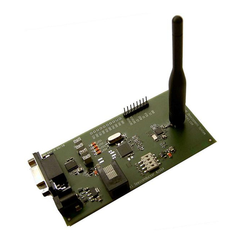
The KSZ8081RNA-EVAL / KSZ8081RND-EVAL (shown in Figure 1) come in a compact form
factor and plugs directly into other boards with Ethernet MACs that expose the RMII interface
through an MII connector. Configuration of the KSZ8081RNA / KSZ8081RND is accomplished
through on-board jumper selections and/or by PHY register access via the MDC/MDIO
management pins at the MII connector.
Figure 1. KSZ8081RNA / KSZ8081RND Evaluation Board
A USB type B connector provides access to the MDC/MDIO management interface, as an
alternative to accessing it through the MII connector. Micrel provides a software utility for
accessing the USB interface from a Windows PC.
Other features include an RJ-45 Jack for Fast Ethernet cable connection, programmable LED
indicator for reporting link status and activity, and a manual reset button for quick reboot after re-
configuration of strapping pins.
The KSZ8081RNA-EVAL / KSZ8081RND-EVAL receive +5V DC input power either through the
MII connector or through the USB connector.

KSZ8081RNA / KSZ8081RND 10Base-T/100Base-TX Evaluation Board User’s Guide
Micrel, Inc. August 17, 2012
Rev. 1.0
7/11
4.1 RMII (Reduced Media Independent Interface)
The KSZ8081RNA-EVAL / KSZ8081RND-EVAL accesses RMII data from the MII connector J4.
This connector is also optionally used for MDC/MDIO management bus access and for 5V power
to the evaluation board. Figure 2 shows the KSZ8081RNA-EVAL / KSZ8081RND-EVAL
connected to the Micrel KSZ8463RLI Evaluation Board through connector J4.
Figure 2. KSZ8081RNA-EVAL interfacing with KSZ8463RLI Evaluation Board
Two RMII clocking modes are available with the KSZ8081RNA and KSZ8081RND. The
KSZ8081RNA powers up in RMII-25MHz Mode, while the KSZ8081RND powers up in RMII-
50MHz mode. After power-up, both KSZ8081RNA and KSZ8081RND can be programmed via
PHY register 1Fh bit [7] to either 25MHz mode or 50MHz mode.
In 25MHz Mode, a 25MHz crystal is connected to the XI and XO pins of the KSZ8081.
(Alternatively, a 25 MHz oscillator may drive XI.) The KSZ8081 outputs a 50 MHz RMII Reference
Clock on its REF_CLK pin. REF_CLK drives pin 9 of the MII connector J4, for connection to a
MAC RMII device on an attached board.
In 50MHz Mode, the KSZ8081 receives the 50MHz RMII Reference Clock as an input on the XI
pin from pin 12 of the MII connector J4. This clock is sourced from a MAC device (or a separate
clock source) on an attached board. No local 25MHz crystal or oscillator is used.
These two modes have different component installation requirements on the evaluation board, as
shown in Table 1.

KSZ8081RNA / KSZ8081RND 10Base-T/100Base-TX Evaluation Board User’s Guide
Micrel, Inc. August 17, 2012
Rev. 1.0
8/11
RMII Clocking Mode Populate Do Not Populate
KSZ8081RNA 25MHz Mode R11, C16, C17, Y1 R17, R19
KSZ8081RND 50MHz Mode R17, R19 R11, C16, C17, Y1
Table 1. Board Configuration for RMII Clocking Modes
The KSZ8081RNA-EVAL / KSZ8081RND-EVAL have provision for an oscillator in position Y2.
This oscillator is normally not used, and is therefore not populated. If desired, a 25MHz oscillator
(and appropriate resistor installation) may be used in place of oscillator Y1 for 25MHz Mode.
Likewise, a 50MHz oscillator (and appropriate resistor installation) may be used in place of an off-
board RMII reference clock for 50MHz Mode.
The Eval Board has a 40-pin male edge connector that interfaces with and plugs directly into a
Fast Ethernet MAC board with the mating AMP 787170-4 (40-pin, right angle, female) connector.
Table 2 lists the pin outs for the RMII interface on connector J4.
Pin # Signal Pin # Signal
1 +5V 21 +5V
2 MDIO 22 Ground
3 MDC 23 Ground
4 <not used> 24 Ground
5 <not used> 25 Ground
6 RXD[1] 26 Ground
7 RXD[0] 27 Ground
8 CRSDV 28 Ground
9 <not used> 29 Ground
10 RXER 30 Ground
11 <not used> 31 Ground
12 TXCLK 32 Ground
13 TXEN 33 Ground
14 TXD0 34 Ground
15 TXD1 35 Ground
16 <not used> 36 Ground
17 <not used> 37 Ground
18 <not used> 38 Ground
19 <not used> 39 Ground
20 +5V 40 +5V
Table 2. Connector J4 - RMII Pin Definition

KSZ8081RNA / KSZ8081RND 10Base-T/100Base-TX Evaluation Board User’s Guide
Micrel, Inc. August 17, 2012
Rev. 1.0
9/11
4.2 MDC/MDIO Management Interface
The MII Management Interface (MIIM) may be conducted through pins MDC (clock line) and
MDIO (data line) of the KSZ8081RNA / KSZ8081RND. MIIM allows upper-layer devices to
monitor and control the states of the KSZ8081RNA / KSZ8081RND. An external device with
MDC/MDIO capability can be used to read the PHY status or configure the PHY registers. The
MIIM frame format and timing information can be found in the KSZ8081RNA and KSZ8081RND
datasheets and in Clause 22 of the IEEE 802.3 Specification.
Two alternatives are available for accessing the MIIM interface. First, the MDC and MDIO signals
are available on the MII connector J4 that is utilized for the RMII interface to an external MAC
device. Alternatively, the MIIM interface can be accessed through the USB connector CN1.
Note that these two methods are mutually exclusive; use either one or the other, but not both.
The MDC and MDIO pins of the KSZ8081 are always connected to MII connector J4. Therefore,
if MDC and MDIO are driven by a MAC device on the attached board, then this eliminates use of
the USB port. The USB port may be used to access MIIM only if the MDC and MDIO signals are
unconnected on the board attached to MII connector J4.
Also note that the MIIM (MDC and MDIO) signals of the KSZ8081RNA / KSZ8081RND operate at
the VDDIO supply voltage, which is configurable as 3.3 / 2.5 / 1.8 V. When MIIM is accessed
through the MII connector, the user must ensure that the voltage levels are compatible between
the KSZ8081RNA / KSZ8081RND and the connected MAC device. When MIIM is accessed
through USB, voltage translation between the KSZ8081RNA / KSZ8081RND and the USB
interface chip is provided.
4.2.1 USB Interface
When the board attached to MII connector J4 does not drive the MDC and MDIO signals, the
USB interface may be used to access the MIIM interface. The board may be powered either from
the USB interface or from the MII connector J4, as described below. When the USB interface is
used, jumpers JP4 and JP5 must be set properly for power and reset, respectively. Additionally,
jumpers JP6 and JP7 must be installed.
MIIM Interface Access JP6 & JP7
RMII connector J4 Open
USB connector CN1 Close
Table 3. MIIM Source Selection
To access the MIIM through USB, install MicrelSwitchPhyTools on a Windows PC. This software
includes two useful utilities for USB connections to Micrel Ethernet devices. For MIIM access,
use the MicrelMDIOConfigApp.exe application that is included in the MicrelSwitchPhyTools
installation..
4.3 Power
The KSZ8081RNA-EVAL / KSZ8081RND-EVAL can draw 5V power from either the RMII
connector (J4) or from the USB connector (CN1). Table 4 shows the jumper settings for these
two options.

KSZ8081RNA / KSZ8081RND 10Base-T/100Base-TX Evaluation Board User’s Guide
Micrel, Inc. August 17, 2012
Rev. 1.0
10/11
5V Source JP1 JP4 JP5
RMII connector J4 Close pins 1-2 Close pins 1-2 Close pins 2-3
USB connector CN1 Close pins 2-3 Close pins 2-3 Close pins 1-2
Table 4. 5V Power Source Selection
The 5V is regulated to generate 3.3V for the KSZ8081RNA / KSZ8081RND, the USB interface
chip and the LED. A second voltage regulator optionally supplies reduced I/O voltage for the
KSZ8081RNA / KSZ8081RND.
The I/O voltage level of the KSZ8081RNA / KSZ8081RND can be set to one of three different
levels. The jumper settings for these options are shown in Table 5.
KSZ8081
VDDIO Voltage JP2 JP3
3.3V Close 1-2 or 2-3 Close pins 2-3
2.5V Close pins 2-3 Close pins 1-2
1.8V Close pins 1-2 Close pins 1-2
Table 5. VDDIO Voltage Selection
4.4 RMII Loopback Jumpers
The KSZ8081RNA-EVAL / KSZ8081RND-EVAL have a set of jumpers that may be used to
loopback the RMII interface. To loopback, all three jumpers must be installed. The individual
jumpers are defined in Table 6.
Jumper RMII Signals Normal Operation RMII Loopback Mode
J1 CRS_DV / TXEN Open Close
J2 RXD1 / TXD1 Open Close
J3 RXD0 / TXD0 Open Close
Table 6. KSZ8081RNA-EVAL / KSZ8081RND-EVAL Loopback Jumper Definition

KSZ8081RNA / KSZ8081RND 10Base-T/100Base-TX Evaluation Board User’s Guide
Micrel, Inc. August 17, 2012
Rev. 1.0
11/11
4.5 Test Point Definition
The KSZ8081RNA-EVAL / KSZ8081RND-EVAL have several test points. They are defined in the
following table.
Test Point Definition
TP1 SYS_CLK_BTB (50MHz Mode RMII clock,
requires installation of R21)
TP2, TP8, TP9, TP10, TP11 Ground
TP3 MDC
TP4 MDIO
TP5 INTRP
TP6 LED0
Table 7. KSZ8081RNA-EVAL / KSZ8081RND-EVAL Test Point Definition
4.6 RJ-45 Connector
The RJ-45 Connector (J5) connects to standard CAT-5 Ethernet cable to interface with 10Base-T
/ 100Base-TX Ethernet devices.
4.7 LED Indicators
An LED indicator (LED1) is located adjacent to the RJ-45 Connector.
The two LEDs are programmable to LED mode ‘00’ or ‘01’ via register 1Fh bits [5:4], and are
defined in the following table.
LED Mode LED0 (pin 23)
00
Link/Activity Pin
State LED
Definition
No Link H OFF
Link L ON
Activity Toggle Blinking
01
Link Pin
State LED
Definition
No Link H OFF
Link L ON
10 Reserved – not used
11 Reserved – not used
Table 8. KSZ8081RNA / KSZ8081RND LED Definition
This manual suits for next models
3
Table of contents
Other Micrel Transceiver manuals
Popular Transceiver manuals by other brands
ON Semiconductor
ON Semiconductor NCV7425EVB user manual

National Instruments
National Instruments NI PXIe-5644R Getting started guide

Kenwood
Kenwood TM-541E instruction manual

ELECRAFT
ELECRAFT KX3 owner's manual

Nortel
Nortel Picocell 1900 Installation
National Instruments
National Instruments USRP-2920 Getting started guide

HWM
HWM Multilog LX 2 user manual

Spender
Spender TC-245S instruction manual

Badger Meter
Badger Meter ORION SE Installation & operation manual

Hallicrafters
Hallicrafters SR-400A CYCLONE III Operating and service instructions

Super Star
Super Star 3900 OLED user manual

Vcom
Vcom IduBST1918 Installation and operation guide
