Micrel KSZ9031RNX User manual

Micrel, Inc. ♦2180 Fortune Drive ♦San Jose, CA 95131 ♦U.S.A.
408-944-0800 (voice) ♦408-474-1000 (fax)
http://www.Micrel.com
KSZ9031RNX
Gigabit Ethernet Transceiver
with RGMII Support
KSZ9031RNX-EVAL Board User’s Guide
Revision 1.1 / August 2012
© Micrel, Inc. 2012
All rights reserved
Micrel is a registered trademark of Micrel and its subsidiaries in the
United States and certain other countries. All other trademarks are the
property of their respective owners.
The information furnished by Micrel in this datasheet is believed to be accurate and reliable. However, no responsibility is
assumed by Micrel for its use. Micrel reserves the right to change circuitry and specifications at any time without
notification to the customer. Micrel Products are not designed or authorized for use as components in life support
appliances, devices or systems where malfunction of a product can reasonably be expected to result in personal injury.
Life support devices or systems are devices or systems that (a) are intended for surgical implant into the body or (b)
support or sustain life, and whose failure to perform can be reasonably expected to result in a significant injury to the user.
A Purchaser's use or sale of Micrel Products for use in life support appliances, devices or systems is at Purchaser's own
risk and Purchaser agrees to fully indemnify Micrel for any damages resulting from such use or sale.

KSZ9031RNX-EVAL Board User’s Guide
Micrel, Inc. August 17, 2012
Rev. 1.1
2/22
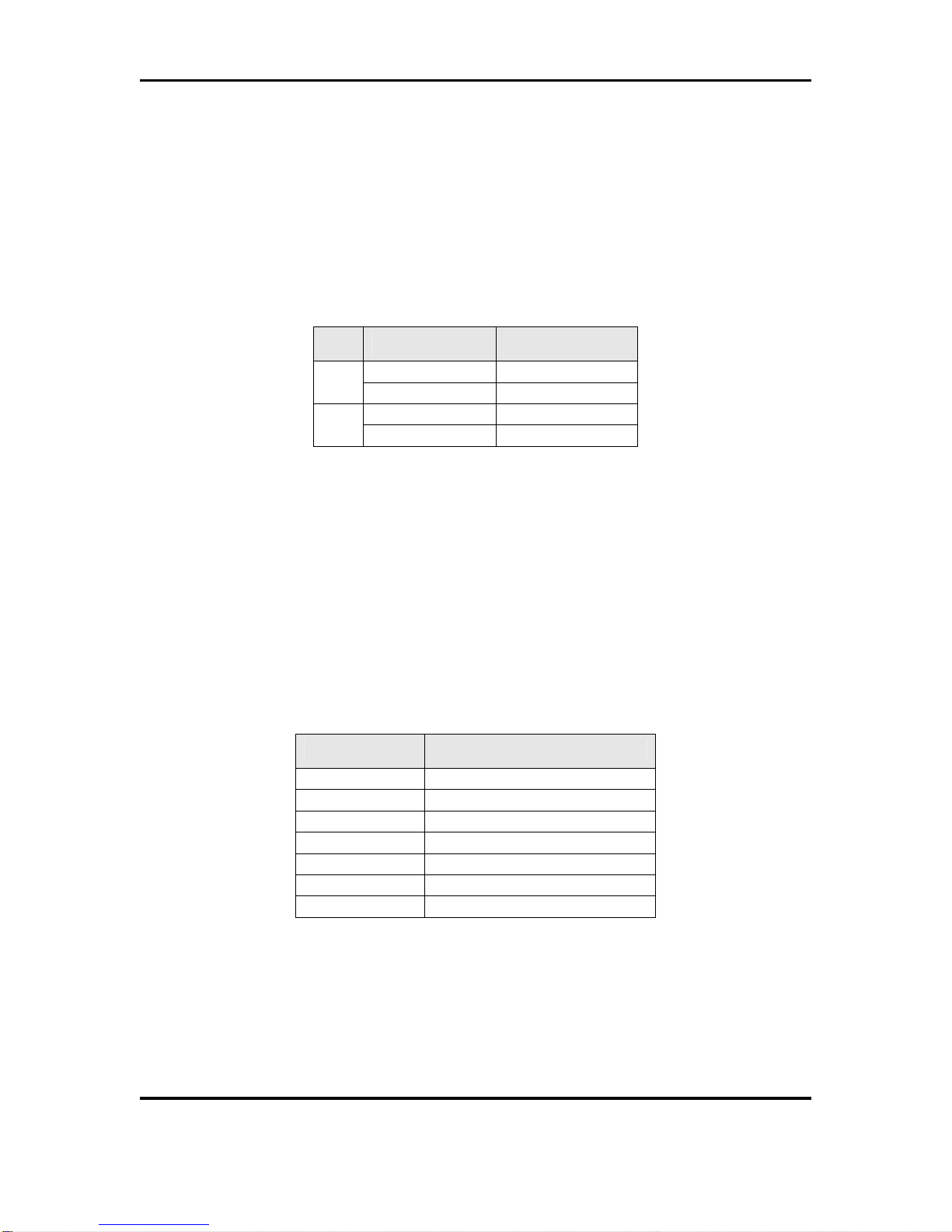
Revision History
Revision Date Summary of Changes
1.0 6/15/12 Initial Release
1.1 8/17/12 Removed 5V DC Adapter from EVAL Kit.
Updated Micrel MDIO Configuration Software installation and
usage sections.

KSZ9031RNX-EVAL Board User’s Guide
Micrel, Inc. August 17, 2012
Rev. 1.1
3/22
Table of Contents
1.0 Introduction ............................................................................. 5
2.0 Board Features........................................................................ 5
3.0 Evaluation Kit Contents.......................................................... 5
4.0 Hardware Description............................................................. 6
4.1 Jumper Setting & Definition .................................................................................. 7
4.2 Test Point Definition............................................................................................... 9
4.3 RJ-45 Copper Interface .......................................................................................... 9
4.4 LED Indicators ........................................................................................................ 9
4.4.1 Single LED Mode ..................................................................................... 10
4.4.2 Tri-color Dual LED Mode......................................................................... 10
4.5 Reduced Gigabit Media Independent Interface (RGMII) ................................... 11
4.5.1 RGMII Loop Back..................................................................................... 11
4.5.2 RGMII Connection to GMAC................................................................... 12
4.6 USB Port ................................................................................................................ 12
5.0 Micrel MdioConfig Software – Installation.......................... 13
5.1 MicrelSwitchPhyQATools Installation................................................................ 13
5.2 USB Driver Installation......................................................................................... 16
6.0 Micrel MdioConfig Software – Application Program.......... 19
6.1 Windows Command Prompt – Command Line program.................................. 19
6.1.1 Running the program.............................................................................. 19
6.1.2 Read/Write access to KSZ9031RNX PHY registers.............................. 20
6.1.3 Creating and running a script file .......................................................... 21

KSZ9031RNX-EVAL Board User’s Guide
Micrel, Inc. August 17, 2012
Rev. 1.1
4/22
List of Figures
Figure 1. KSZ9031RNX-EVAL Board............................................................................................. 6
Figure 2. KSZ9031RNX-EVAL Board – RGMII Loop Back.......................................................... 11
List of Tables
Table 1. KSZ9031RNX-EVAL Board – Jumper Definition.............................................................. 7
Table 2. Strapping Pin Definitions for KSZ9031RNX-EVAL Board Jumpers................................. 8
Table 3. KSZ9031RNX-EVAL Board – Test Point Definition ......................................................... 9
Table 4: Single LED Mode – LED Definition ................................................................................ 10
Table 5: Tri-color Dual LED Mode – LED Definition..................................................................... 10
Table 6. RGMII Signals access at series termination / jumper resistor locations........................ 12

KSZ9031RNX-EVAL Board User’s Guide
Micrel, Inc. August 17, 2012
Rev. 1.1
5/22
1.0 Introduction
The KSZ9031RNX is a completely integrated triple speed (10Base-T/100Base-TX/1000Base-T)
Ethernet Physical Layer Transceiver for transmission and reception of data over standard CAT-5
unshielded twisted pair (UTP) cable.
The KSZ9031RNX reduces board cost and simplifies board layout by using on-chip termination
resistors for the four differential pairs and by integrating a LDO controller to drive a low cost
MOSFET to supply the 1.2V core.
On the copper media interface, the KSZ9031RNX can automatically detect and correct for
differential pair misplacements and polarity reversals, and correct propagation delays and re-sync
timing between the four differential pairs, as specified in the IEEE 802.3 standard for 1000Base-T
operation.
The KSZ9031RNX provides the Reduced Gigabit Media Independent Interface (RGMII) for direct
connection to RGMII MACs in Gigabit Ethernet Processors and Switches for data transfer at
10/100/1000 Mbps speed.
The KSZ9031RNX Evaluation Board (KSZ9031RNX-EVAL) provides a comprehensive platform
to evaluate the KSZ9031RNX features. All KSZ9031RNX configuration pins are accessible either
by jumpers, test points or interface connectors.
2.0 Board Features
•Micrel KSZ9031RNX 10Base-T/100Base-TX/1000Base-T Physical Layer Transceiver
•RJ-45 Jack for Ethernet cable interface
•Auto MDI/MDI-X for automatic detection and correction for straight-through and crossover
cables
•RGMII Loopback for standalone evaluation
•LED Indicators for link status and activity
•Jumpers to configure strapping pins
•Manual Reset Button for quick reboot after re-configuration of strapping pins
•USB port for MDC/MDIO programming access to KSZ9031RNX PHY registers
3.0 Evaluation Kit Contents
The KSZ9031RNX Evaluation Kit includes the following hardware:
•KSZ9031RNX-EVAL Board (a.k.a. KSZ9031RNX Socket Board)
And a design package with the following collaterals:
•KSZ9031RNX Evaluation-Socket Board Schematic (PDF and OrCAD DSN file)
•KSZ9031RNX Evaluation-Socket Board Gerber & PADS PowerPCB Files
•KSZ9031RNX Evaluation-Socket Board BOM
•KSZ9031RNX Evaluation-Socket Board User’s Guide (this document)
•KSZ9031RNX IBIS Model (separate files for 1.8V, 2.5V, and 3.3V VDD I/O voltages)
•Micrel MDIO Configuration Software

KSZ9031RNX-EVAL Board User’s Guide
Micrel, Inc. August 17, 2012
Rev. 1.1
6/22
4.0 Hardware Description
The KSZ9031RNX-EVAL board provides a standalone evaluation platform for the KSZ9031RNX
Gigabit Ethernet Transceiver. Configuration of the KSZ9031RNX is accomplished through on-
board jumper selections and/or by PHY register access via the KSZ9031RNX MDC/MDIO
management pins via the USB port (CN1).
Figure 1. KSZ9031RNX-EVAL Board
Features include a RJ-45 Jack for 10/100/1000 Ethernet speed cable connection, programmable
LED indicators for reporting link status and activity, and a manual reset button for quick reboot
after re-configuration of strapping pins.
On-board, RGMII receive output clock and signals are looped back to RGMII transmit input clock
and signals to provide a standalone evaluation platform for the KSZ9031RNX device. Optionally,
the RGMII loop back path can be opened to allow the RGMII signals to be wired to a Gigabit MAC
on another board.
The KSZ9031RNX-EVAL board receives power from a DC power jack (J13). Any DC power
adapter in the range of 5V to 12V with a current rating of 2 Amp or better can be used.
Power Jack
(J13)
Reset
(S1)
USB Port
(CN1)
RJ-45 Jack
(RJ1)
RGMII
Signals
KSZ9031RN
X
Single LEDs
(D2, D1)
Tri-color Dual LED
(D10) KSZ9031RNX-
EVAL Board

KSZ9031RNX-EVAL Board User’s Guide
Micrel, Inc. August 17, 2012
Rev. 1.1
7/22
4.1 Jumper Setting & Definition
At power-up, the KSZ9031RNX device is configured via strapping pins that are set by external
pull-up and pull-down resistors. The KSZ9031RNX-EVAL board provides jumpers for the
KSZ9031RNX device strap-in settings and for selective board options.
Jumpers allow for quick configuration and re-configuration. To override the current KSZ9031RNX
device and board settings, simply select and close the desired jumper setting(s) and toggle the
on-board manual reset button (S1) for the new setting(s) to take effect.
The KSZ9031RNX-EVAL board jumper settings are defined in the table below.
Jumper KSZ9031RNX Pin Name Setting Function
KSZ9031RNX Device Strapping Pins
Close pins (1, 2) Set MODE3 = 1JP1 MODE3
Close pins (2, 3) Set MODE3 = 0
Close pins (1, 2) Set MODE2 = 1JP2 MODE2
Close pins (2, 3) Set MODE2 = 0
Close pins (1, 2) Set MODE1 = 1JP3 MODE1
Close pins (2, 3) Set MODE1 = 0
Close pins (1, 2) Set MODE0 = 1JP4 MODE0
Close pins (2, 3) Set MODE0 = 0
Close pins (1, 2) Set PHYAD2 = 1JP19 PHYAD2
Close pins (2, 3) Set PHYAD2 = 0
Close pins (1, 2) Set PHYAD1 = 1JP9 PHYAD1
Close pins (2, 3) Set PHYAD1 = 0
Close pins (1, 2) Set PHYAD0 = 1JP10 PHYAD0
Close pins (2, 3) Set PHYAD0 = 0
Close pins (1, 2) Enable 125 MHz Clock OutputJP16 CLK125_EN
Close pins (2, 3) Disable 125 MHz Clock Output
Close pins (1, 2) Select Single LED ModeJP20 LED_MODE
Close pins (2, 3) Select Tri-color Dual LED Mode
KSZ9031RNX-EVAL Board Settings
Close pins (1, 2) Use for Single LED ModeJP26 LED2
Close pins (2, 3) Use for Tri-color Dual LED Mode
Close pins (1, 2) Use for Single LED ModeJP27 LED1
Close pins (2, 3) Use for Tri-color Dual LED Mode
Close pins (1, 2) Select 2.5V for KSZ903RNX digital I/OsJP23 DVDDH
Close pins (2, 3) Select 3.3V for KSZ9031RNX digital I/Os
Close Jumper Close MDC signal to USB Controller (U8)
JP21 1MDC
Open Jumper Open MDC signal to USB Controller (U8)
Close Jumper Close MDIO signal to USB Controller (U8)
JP22 1MDIO
Open Jumper Open MDIO signal to USB Controller (U8)
Note:
1 JP21 and JP22 connect the MDC/MDIO signals to U8 when U13 is not populated.
Table 1. KSZ9031RNX-EVAL Board – Jumper Definition

KSZ9031RNX-EVAL Board User’s Guide
Micrel, Inc. August 17, 2012
Rev. 1.1
8/22
The following table lists the strapping pin definitions for the KSZ9031RNX-EVAL board jumpers.
Jumper Pin Pin Name Pin Function
JP1
JP2
JP3
JP4
27
28
31
32
MODE3
MODE2
MODE1
MODE0
The MODE[3:0] strap-in pins are latched at power-up /
reset and are defined as follows:
MODE[3:0] Mode
0100 NAND Tree
0111 Chip Power Down
1100 RGMII – advertise 1000Base-T full-
duplex only
1101 RGMII – advertise 1000Base-T full
and half-duplex only
1110 RGMII – advertise all capabilities
(10/100/1000 speed half/full duplex),
except 1000Base-T half-duplex
1111 RGMII – advertise all capabilities
(10/100/1000 speed half/full duplex)
All other MODE[3:0] settings not listed are reserved and
are not used by the KSZ9031RNX-EVAL.
MODE[3:0] = 1111 is the normal RGMII setting and is
set as the default for the board.
JP19
JP9
JP10
35
15
17
PHYAD2
PHYAD1
PHYAD0
The PHY Address is latched at power-up / reset and is
configurable to any value from 0 to 7.
PHY Address bits [4:3] are always set to ‘00’.
PHYAD[2:0] = 001 is set as the default for the board.
JP16 33 CLK125_EN
CLK125_EN is latched at power-up / reset and is defined
as follows:
Pull-up (1) = Enable 125MHz Clock Output
Pull-down (0) = Disable 125MHz Clock Output
Pin 41 (CLK125_NDO) provides the 125MHz reference
clock output option for use by the MAC.
CLK125_EN = 0 is set as the default for the board.
JP20 41 LED_MODE
LED_MODE is latched at power-up / reset and is defined
as follows:
Pull-up (1) = Single LED Mode
Pull-down (0) = Tri-color Dual LED Mode
LED_MODE = 1 is set as the default for the board.
Table 2. Strapping Pin Definitions for KSZ9031RNX-EVAL Board Jumpers

KSZ9031RNX-EVAL Board User’s Guide
Micrel, Inc. August 17, 2012
Rev. 1.1
9/22
4.2 Test Point Definition
The KSZ9031RNX-EVAL board has 16 usable test points, as defined in the following table.
Test Point Definition
TP4 Interrupt Signal (KSZ9031RNX pin 38) with 4.7K external pull-up
TP7 AVDDH voltage – KSZ9031RNX power pins
TP12 AVDDL voltage – KSZ9031RNX power pins
TP14 DVDDL – KSZ9031RNX power pins
TP15 AVDDL_PLL – KSZ9031RNX power pin
TP16 DVDDH – KSZ9031RNX power pins
TP17 Signal Ground
TP18 Signal Ground
TP19 Signal Ground
TP20 Signal Ground
TP24 Signal Ground
TP33 Exposed ground connection to KSZ9031RNX paddle ground
(bottom of chip); Test point is located on solder side of PCB.
TP34 End point for board trace delay for RGMII RX_CLK output clock;
Refer to KSZ9031RNX-EVAL Board Schematic for more details.
TP35 1.8ns (10000 mils) board trace delay for RGMII RX_CLK output
clock, starting from resistor R144; Refer to KSZ9031RNX-EVAL
Board Schematic for more details.
TP36-TP37 450ps (2500 mils) board trace delay for RGMII RX_CLK output
clock; Refer to KSZ9031RNX-EVAL Board Schematic for more
details.
Table 3. KSZ9031RNX-EVAL Board – Test Point Definition
4.3 RJ-45 Copper Interface
The RJ-45 copper interface (RJ1) connects to standard unshielded twisted pair (UTP) CAT-5
Ethernet cable to interface with 10Base-T/100Base-TX/1000Base-T network devices.
The KSZ9031RNX copper media interface can automatically detect and correct for differential
pair misplacements and polarity reversals, and correct propagation delays and re-sync timing
between the four differential pairs, as specified in the IEEE 802.3 standard for 1000Base-T
operation.
Auto MDI/MDI-X is supported for automatic detection and correction for straight and crossover
cables when interfacing to link partners with fixed MDI or MDI-X setting.
4.4 LED Indicators
The KSZ9031RNX device provides two programmable LED output pins, LED2 (pin 15) and LED1
(pin 17). On the KSZ9031RNX-EVAL board, these two LED pins are connected to two sets of
LEDs to support two LED configurations: Single LED mode and Tri-color Dual LED mode.
KSZ9031RNX-EVAL Board User’s Guide
Micrel, Inc. August 17, 2012
Rev. 1.1
10/22
4.4.1 Single LED Mode
To enable Single LED mode,
•Close pins (1, 2) of jumpers JP26 and JP27 to select D2 and D1, respectively for the
single LEDs.
•Close pins (1, 2) of jumper JP20 to set the LED_MODE strap-in for Single LED mode.
•Power-up the board.
After board power-up, the on-board D2 and D1 LEDs are defined as follows:
LED LED Definition Link / Activity
OFF Link off
D2 Green – ON Link on (any speed)
OFF No Activity
D1 Green – Blinking Activity (RX, TX)
Table 4: Single LED Mode – LED Definition
4.4.2 Tri-color Dual LED Mode
To enable Tri-color Dual LED mode,
•Close pins (2, 3) of jumpers JP26 and JP27 to select D10 for the tri-color dual LED.
•Close pins (2, 3) of jumper JP20 to set the LED_MODE strap-in for Tri-color Dual LED
mode.
•Power-up the board.
After board power-up, the on-board D10 LED is defined as follows:
LED: D10 Link / Activity
OFF Link off
Green – ON 1000Mbps Link / No Activity
Green – Blinking 1000Mbps Link / Activity (RX, TX)
Red – ON 100Mbps Link / No Activity
Red – Blinking 100Mbps Link / Activity (RX, TX)
Orange – ON 10Mbps Link / No Activity
Orange – Blinking 10Mbps Link / Activity (RX, TX)
Table 5: Tri-color Dual LED Mode – LED Definition
KSZ9031RNX-EVAL Board User’s Guide
Micrel, Inc. August 17, 2012
Rev. 1.1
11/22
4.5 Reduced Gigabit Media Independent Interface (RGMII)
The KSZ9031RNX-EVAL board provides open access to the KSZ9031RNX device’s RGMII
signals, and enables the RGMII signals to be wired for the following two usages:
•RGMII Loop Back
•RGMII Connection to GMAC
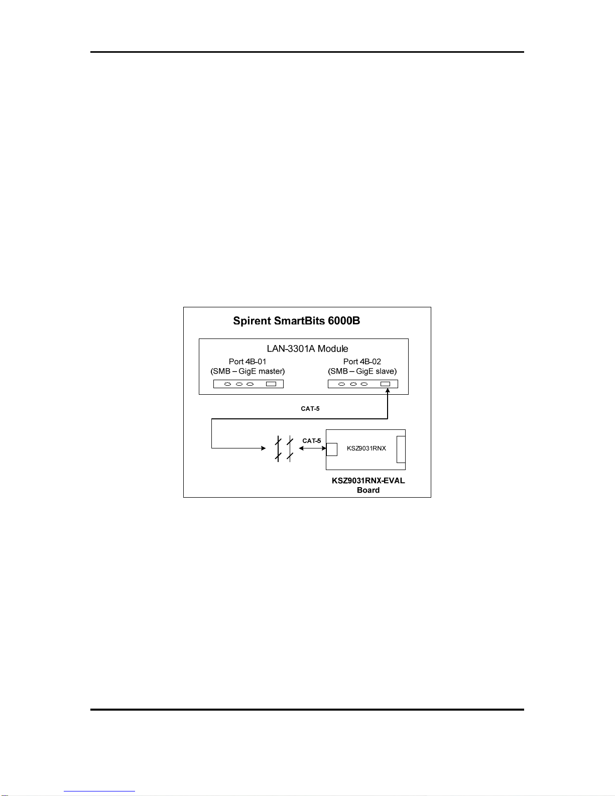
4.5.1 RGMII Loop Back
The KSZ9031RNX-EVAL board is shipped with the RGMII signals configured for RGMII Loop
Back. Resistors [R14, R16, R136-R139] are populated to connect the RGMII output clock and
signals to their respective RGMII input clock and signals, thru resistors [R18, R17, R143, R142,
R141, R140], respectively. Refer to KSZ9031RNX-EVAL Board Schematic for details.
RGMII Loop Back enables the KSZ9031RNX device to operate as a standalone evaluation
platform without the need of an external GMAC. Ethernet traffic from the link partner (Spirent
SmartBits 6000B in the following figure) are received by the KSZ9031RNX device, looped back
externally via RGMII pins, and transmitted back to the link partner.
Figure 2. KSZ9031RNX-EVAL Board – RGMII Loop Back
RGMII Loop Back is supported for 1000Base-T and 100Base-TX only. 10Base-T requires a MAC
due to preamble consumption, and therefore is not supported.

KSZ9031RNX-EVAL Board User’s Guide
Micrel, Inc. August 17, 2012
Rev. 1.1
12/22
4.5.2 RGMII Connection to GMAC
The KSZ9031RNX-EVAL board exposes the RGMII signals at the following series termination
(49.9 Ohm) / jumper (0 Ohm) resistor locations, as indicated in the following table.
Resistor
(PCB location) KSZ9031RNX-EVAL
Signal Name
RGMII
Signal Name
(per spec)
R14 left pad
(PCB – top side) RX_CLK RXC
R16 left pad
(PCB – top side) RX_DV RX_CTL
R136 left pad
(PCB – top side) RXD0 RXD0
R137 left pad
(PCB – top side) RXD1 RXD1
R138 left pad
(PCB – top side) RXD2 RXD2
R139 left pad
(PCB – top side) RXD3 RXD3
R18 top pad
(PCB – bottom side) GTX_CLK TXC
R17 left pad
(PCB – top side) TX_EN TX_CTL
R143 top pad
(PCB – bottom side) TXD0 TXD0
R142 top pad
(PCB – bottom side) TXD1 TXD1
R141 top pad
(PCB – bottom side) TXD2 TXD2
R140 top pad
(PCB – bottom side) TXD3 TXD3
Table 6. RGMII Signals access at series termination / jumper resistor locations
Resistors [R14, R16, R136-R139] for the RGMII output clock and signals and the corresponding
resistors [R18, R17, R143, R142, R141, R140] for the RGMII input clock and signals can be
removed to open the RGMII Loop Back path and allow the RGMII signals (in the above table) to
be wired to a GMAC on another board for evaluation and testing.
4.6 USB Port
The USB port (CN1) provides programming access to the KSZ9031RNX device’s PHY registers
through its MDC/MDIO management pins.
See following software section for PHY register access.
KSZ9031RNX-EVAL Board User’s Guide
Micrel, Inc. August 17, 2012
Rev. 1.1
13/22
5.0 Micrel MdioConfig Software – Installation
The Micrel MDIO Configuration Software (MdioConfig.exe program) runs on a PC/NOTEBOOK
with the Window XP or 7 Operating System. It communicates with the KSZ9031RNX-EVAL board
via USB to provide programming access to the KSZ9031RNX PHY registers.
The Micrel software is provided in a Microsoft Windows Installer installation package file (*.msi
file) with the following file name.
MicrelSwitchPhyQATools_x.xx.msi // where x.xx is the release version number
5.1 MicrelSwitchPhyQATools Installation
Before running the MicrelSwitchPhyQATools installation, make sure previously installed version
of the MicrelSwitchPhyQATools software has been removed and the USB cable to the
KSZ9031RNX-EVAL board is unplugged.
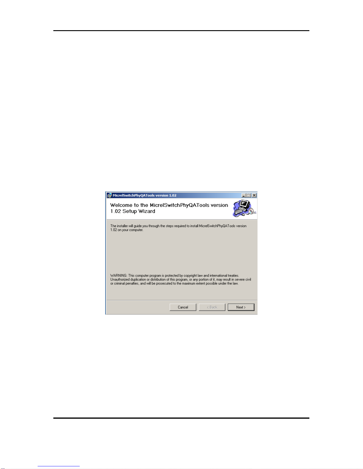
To unpack the MicrelSwitchPhyQATools_x.xx.msi file and start the installation, double click on
the file name from Windows Explorer, and proceed with the following steps:
1. At the “Welcome” screen, press the Next> button.
KSZ9031RNX-EVAL Board User’s Guide
Micrel, Inc. August 17, 2012
Rev. 1.1
14/22
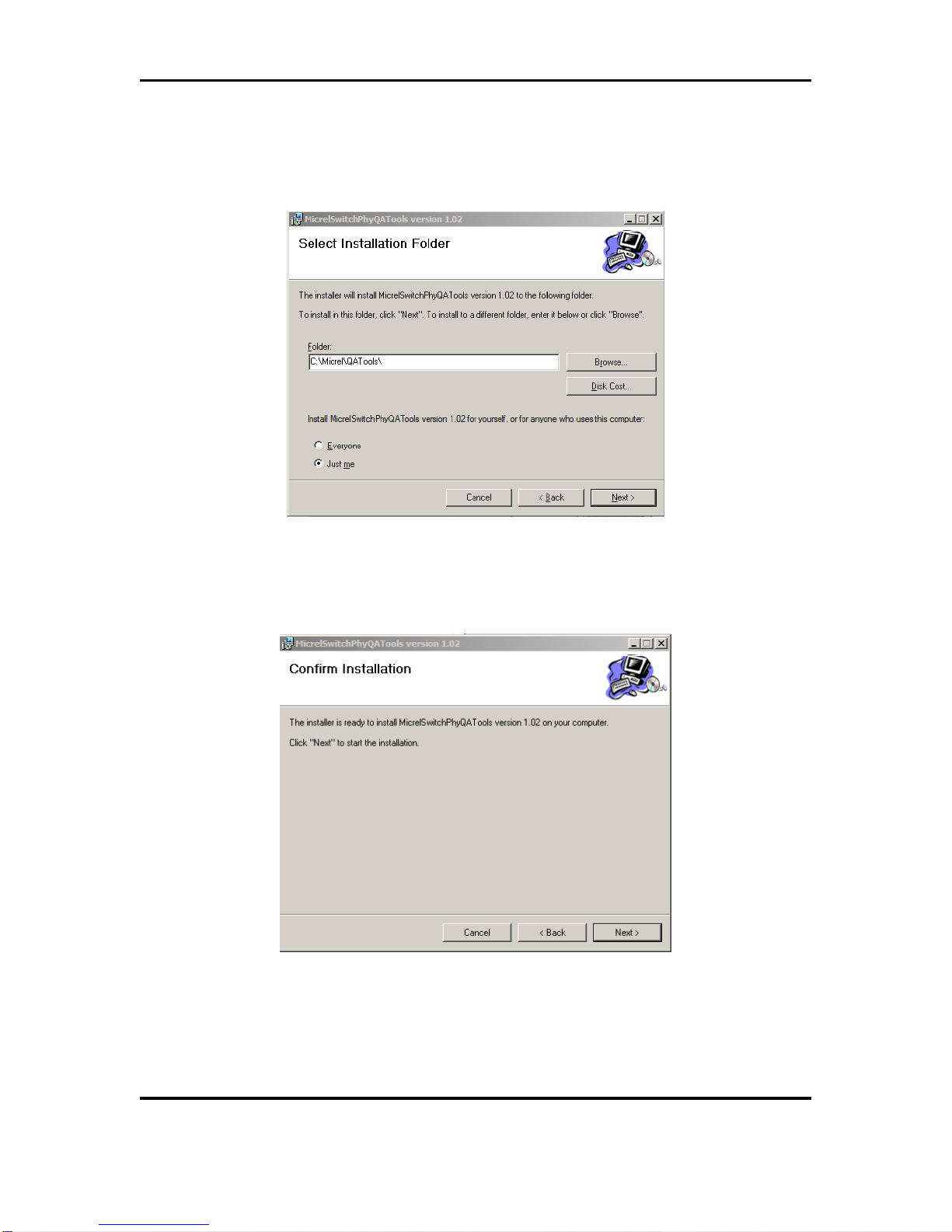
2. At the “Select Installation Folder” screen,
a. Select the folder for the software installation (c:\Micrel\QATools\ is the default
installation folder).
b. Press the Next> button.
3. At the “Confirm Installation” screen,
a. Press the Next> button for the installation to proceed.
b. Wait a few seconds for the installation to finish.

KSZ9031RNX-EVAL Board User’s Guide
Micrel, Inc. August 17, 2012
Rev. 1.1
15/22
4. When the installation is finished, the “Installation Complete” screen is returned. Press
the Close> button to exit.
After the MicrelSwitchPhyQATools installation, an installation folder (c:\Micrel\QATools\ is the
default installation folder) is created containing the mdioConfig application program and software
drivers for the KSZ9031RNX-EVAL board’s USB port.
KSZ9031RNX-EVAL Board User’s Guide
Micrel, Inc. August 17, 2012
Rev. 1.1
16/22
5.2 USB Driver Installation
Before installing the USB driver, complete the MicrelSwitchPhyQATools software installation in
the previous section to extract the USB driver from the MicrelSwitchPhyQATools_x.xx.msi
installation file and have it copied to the created installation folder.
Power-up the KSZ9031RNX-EVAL Board and connect USB cable from board to PC/NOTEBOOK
with the Windows XP or 7 Operating System to initiate the USB driver installation, and proceed
with the following steps:
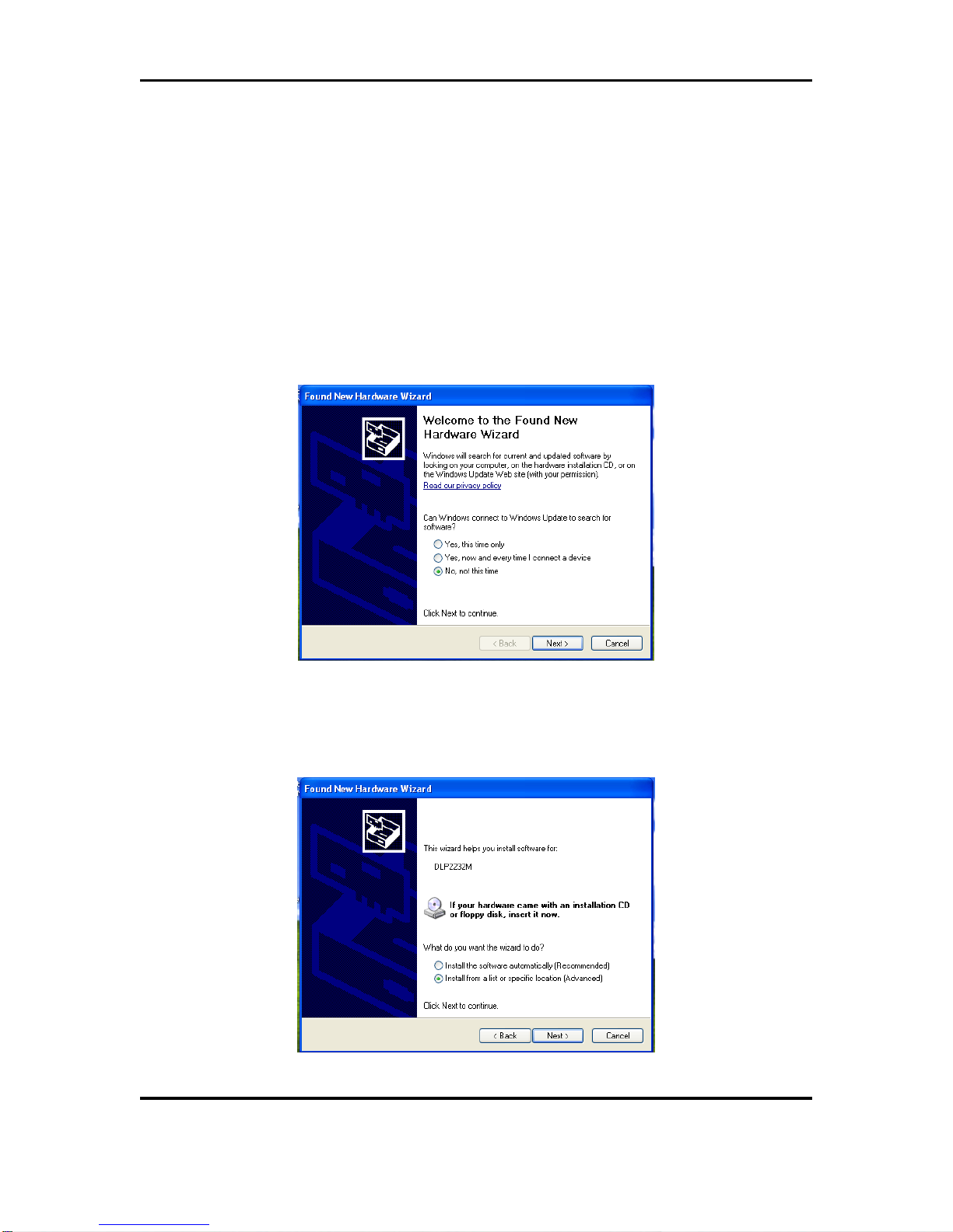
1. Windows XP detects the KSZ9031RNX-EVAL board’s USB device. At the “Welcome to
the Found New Hardware Wizard” screen,
a. Select “No, not this time”.
b. Press the Next> button.
2. At the “… install software for:” screen,
a. Select “Install from a list or specific location (Advanced)”.
b. Press the Next> button.
KSZ9031RNX-EVAL Board User’s Guide
Micrel, Inc. August 17, 2012
Rev. 1.1
17/22
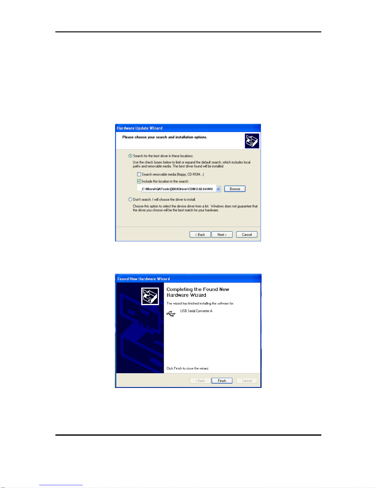
3. At the “Please choose your search and installation options” screen,
a. Select “Include this location in the search:”
b. Press the Browse button and navigate to and select the USB driver directory
(C:\Micrel\QATools\D2XXDriver\CDM 2.02.04 WHQL Certified is the USB
driver directory for the default installation folder).
c. Press the Next> button for the USB driver installation to proceed.
d. Wait for the USB driver installation to finish.
4. At the “Completing the Found New Hardware Wizard” screen, press the Finish button
to close the wizard and exit.

KSZ9031RNX-EVAL Board User’s Guide
Micrel, Inc. August 17, 2012
Rev. 1.1
18/22
5. After the USB driver installation, verify the USB driver is installed.
a. Go to the Windows System Properties box (select the System icon under
Windows Start Menu -> Settings -> Control Panel).
b. Press the Device Manager button
c. Scroll down to the end of Universal Serial Bus controllers to verify “USB Serial
Converter A” and “USB Serial Converter B” are installed.
KSZ9031RNX-EVAL Board User’s Guide
Micrel, Inc. August 17, 2012
Rev. 1.1
19/22
6.0 Micrel MdioConfig Software – Application Program
The Micrel MdioConfig application program resides in the software installation folder created in
the previous section (c:\Micrel\QATools\ is the default installation folder). The following
application program in the folder will be used to provide read/write access to the KSZ9031RNX
PHY registers.
•mdioConfig.exe // Windows Command Prompt program
6.1 Windows Command Prompt – Command Line program
The mdioConfig.exe program is a command line interface program.
6.1.1 Running the program
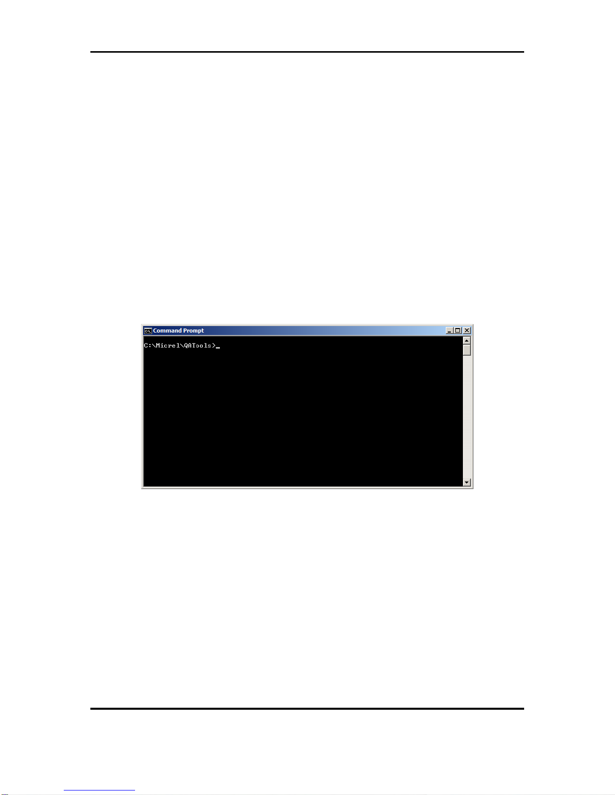
The mdioConfig.exe program is executed from a Windows Command Prompt. Open a Windows
Command Prompt (select the Command Prompt under Windows Start Menu -> Programs ->
Accessories) and go to the mdioConfig.exe program directory (c:\Micrel\QATools\ is the program
directory for the default installation folder), as shown in the following figure.
mdioConfig.exe Program – Windows Command Prompt
The mdioConfig.exe program is started by typing the mdioConfig.exe program name at the
Windows Command Prompt and pressing the <ENTER> key.
KSZ9031RNX-EVAL Board User’s Guide
Micrel, Inc. August 17, 2012
Rev. 1.1
20/22
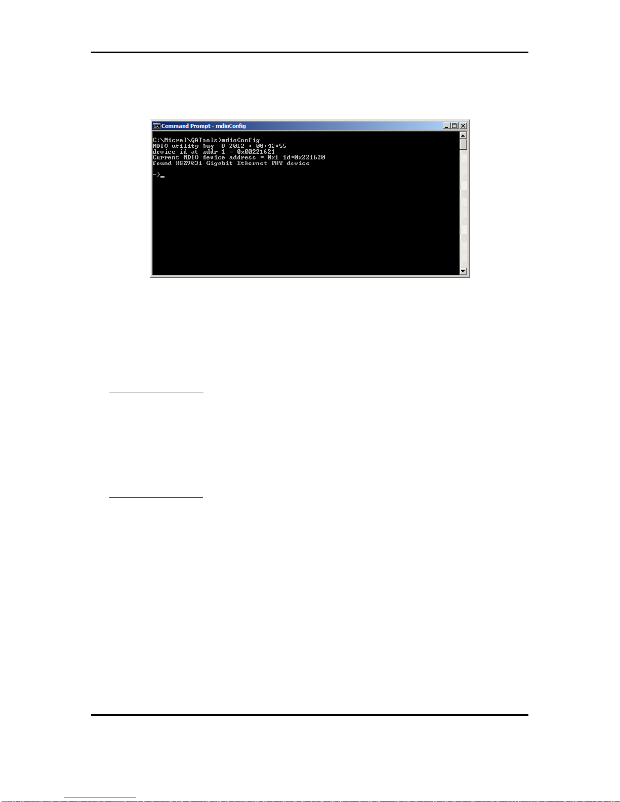
After pressing the <ENTER> key at the previous screen, the program will automatically detect
and set the KSZ9031RNX PHY address for the programming session, and then display the
command line prompt, “->”, as shown in the following figure.
mdioConfig.exe Program – Command Line Prompt
6.1.2 Read/Write access to KSZ9031RNX PHY registers
Direct register read and direct register write can be used to check and/or update individual PHY
register setting, as needed. The following are the commands and parameters:
Direct Register Read
r [register address (hex)]
r 0 // Read PHY register 0h
r 1 // Read PHY register 1h
r 2 // Read PHY register 2h
r 3 // Read PHY register 3h
Direct Register Write
w [register address (hex)] [written value (hex)]
w 0 8000 // Write PHY register 0h with value 0x8000h
w 0 2500 // Write PHY register 0h with value 0x2500h
This manual suits for next models
1
Table of contents
Other Micrel Transceiver manuals


