MICRO-AIR EasyTouch 357 User manual

1
©2021 Micro-Air Corp October 13, 2021; revision 1.7
EasyTouch
357
Operating Manual
Revision 1.7

2
©2021 Micro-Air Corp October 13, 2021; revision 1.7
Contents
Special note on temperature sensors used in the system............................................................................3
Installing the thermostat ..............................................................................................................................4
Removing the old thermostat...................................................................................................................4
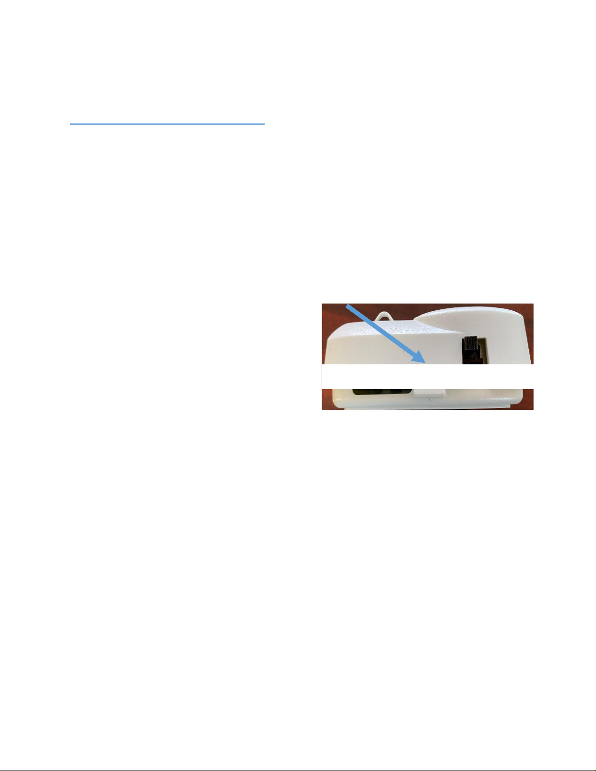
Wiring the thermostat ..............................................................................................................................4
Mounting the thermostat .........................................................................................................................5
Initial setup instructions ...............................................................................................................................6
Available modes........................................................................................................................................6
Connecting remotely.................................................................................................................................6
Indoor temperature measurement ..............................................................................................................6
Improving measurement ..........................................................................................................................6
Operating the thermostat.............................................................................................................................7
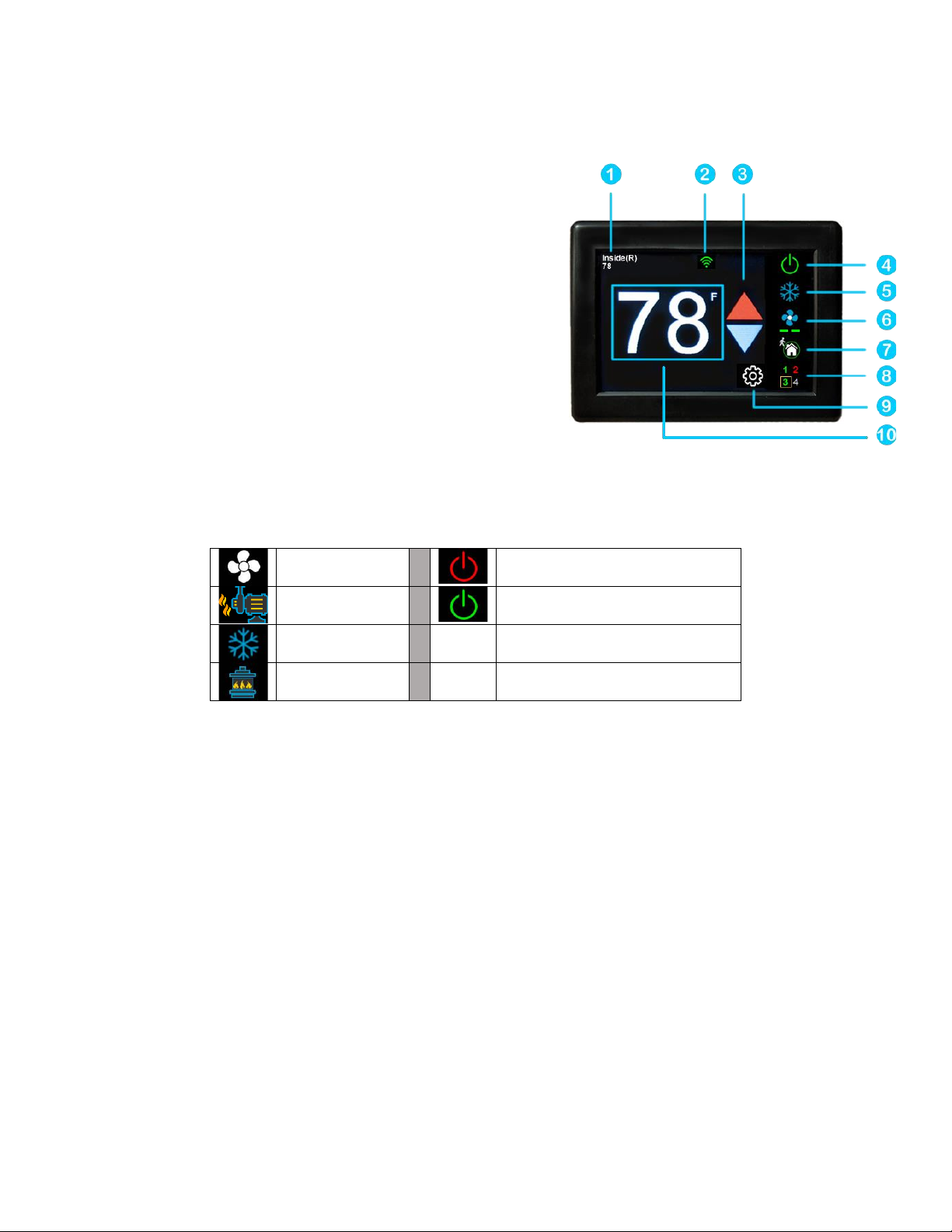
Main screen...............................................................................................................................................7
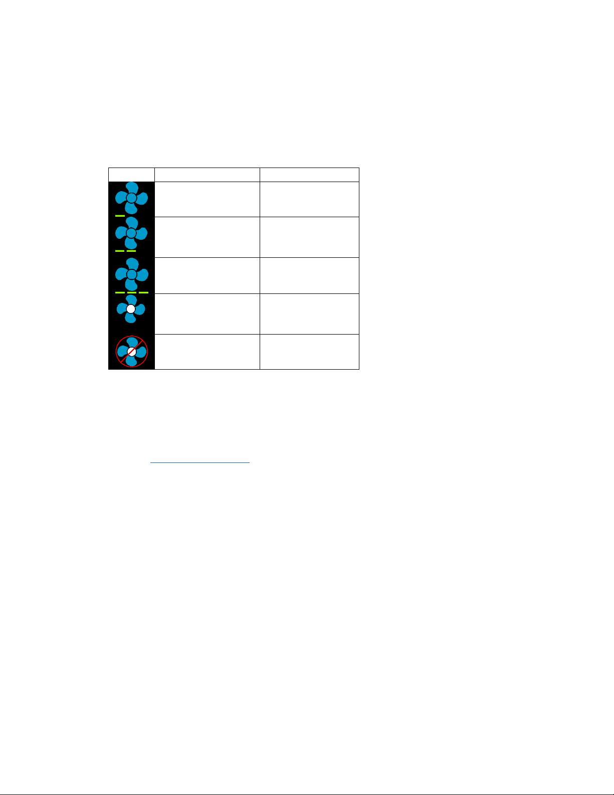
Additional indications on main screen .................................................................................................8
Schedule screen ........................................................................................................................................9
Setting a change event..........................................................................................................................9
12- or 24-hour format...........................................................................................................................9
Setting the time ....................................................................................................................................9
Enabling the schedule...........................................................................................................................9
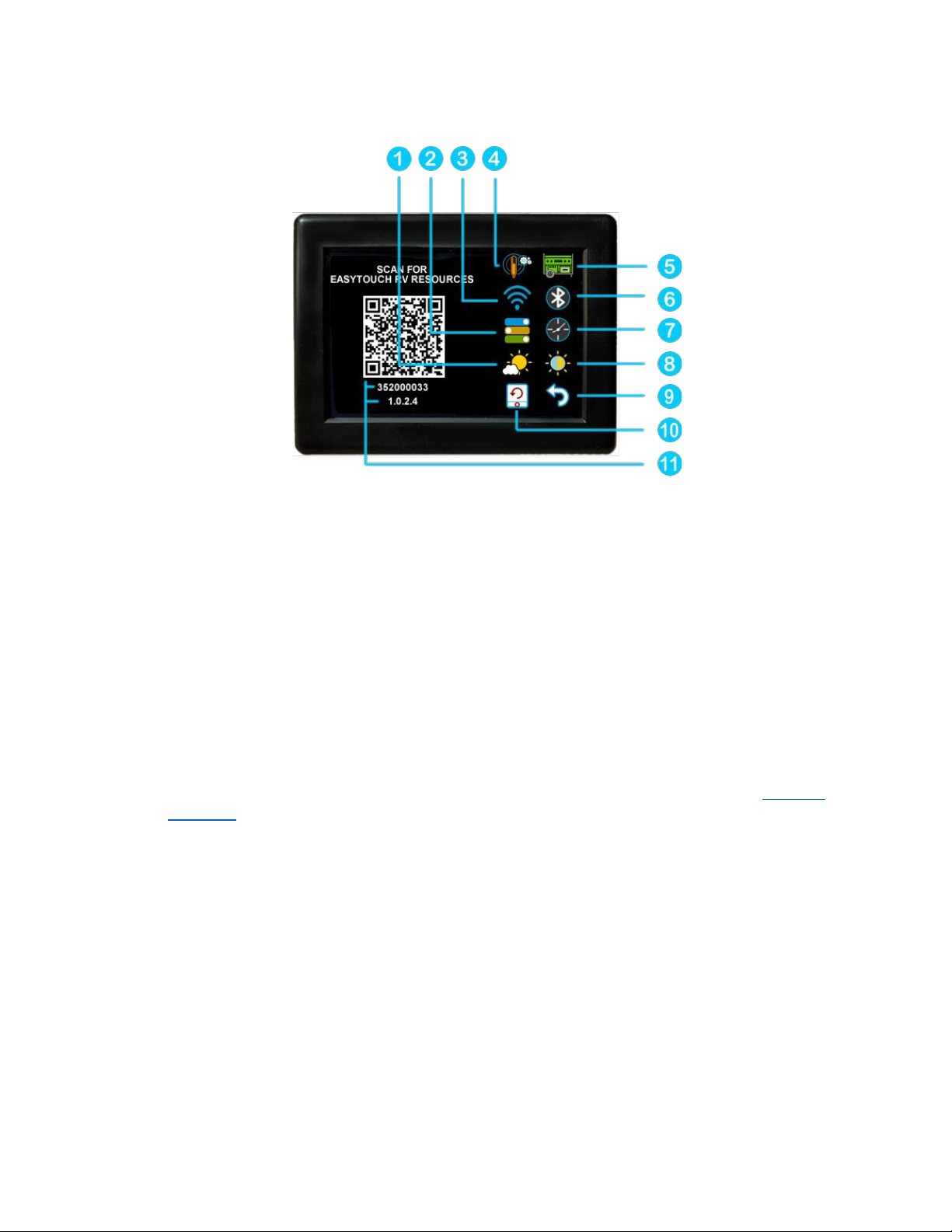
Settings Screen............................................................................................................................................10
Gas Heat Override...................................................................................................................................11
Smart device application only features ......................................................................................................11
Reset device............................................................................................................................................11
Calibrate Touchscreen ............................................................................................................................11
Check for updates ...................................................................................................................................11
Notifications............................................................................................................................................11
Appendix A: Installation Troubleshooting ..................................................................................................12
Appendix B: WIFI Troubleshooting .............................................................................................................12
No WIFI Icon............................................................................................................................................12
Red WIFI Icon ..........................................................................................................................................12
Appendix C: Connecting remotely ..............................................................................................................13
First connection steps.............................................................................................................................13
Adding a control......................................................................................................................................13

3
©2021 Micro-Air Corp October 13, 2021; revision 1.7
Connecting to a new WIFI network ........................................................................................................13
Updating the thermostat ........................................................................................................................13
Special note on temperature sensors used in the system
The EasyTouch thermostat operates in tandem with the control board in the air conditioner. The
Dometic CCC1 control boards used in the air conditioning system do not report the local temperature at
the air conditioner down to the thermostat. As a result, the EasyTouch RV 357 thermostat will report
only the inside temperature derived from sensor inside the thermostat. This temperature will be the
same for all zones regardless of location.
The air conditioner control boards use their own sensor for measuring temperature and
determining when to turn on heating or cooling. These sensors can be found in any number of locations
in the RV, including INSIDE duct work! They are not always accurate so there can be a disparity between
the temperature shown on the display and the action of heating and cooling. If your system appears to
have a significant variation between the set point and the reported inside temperature and/or the
actual room temperature in a zone, it may indicate a defective or poorly placed air sensor.
Alerts to your EasyTouch smart device application issued by the EasyTouch RV 357 thermostat
are based on the temperature measured at the faceplate of the EasyTouch RV thermostat. The
thermostat location controls that report. You may need to make some adjustments in the environment
where the thermostat is located in order for it to report a similar temperature to that of the remote
sensors of the air conditioners. The thermostat should be mounted in a location that gives it a good
chance of reading accurate room temperature.

4
©2021 Micro-Air Corp October 13, 2021; revision 1.7
The EasyTouch 357 model thermostat was designed to replace certain Dometic™multi-zone
capable thermostats. Original thermostats replaced by this model are a five-button configuration with a
display alongside the buttons. If your thermostat is not of this style, please contact Micro-Air
https://www.micro-air.com/SupportRequest to verify the thermostat you received is correct for your
application.
Note: To replace the older four button displays with this thermostat, all air conditioning control
boards must be replaced with the CCC control boards compatible with five button controls.
Installing the thermostat
There are three steps to installing the thermostat. First remove your old thermostat. Next
disconnect and reconnect the wiring. Finally install the mounting pins to the wall and mount your new
thermostat.
Removing the old thermostat
Locate the tab on the center bottom of the thermostat as shown in figure 1. Insert a small screw
driver from the side of the thermostat under the tab and lift the thermostat off from the bottom.
Unplug the thermostat from the cable by pressing the
release tab on the connector. Remove the four back
plate screws and remove the back plate from the wall.
Wiring the thermostat
All models feature a simple telephone style
modular jack. This is a six-pin version of a common
Ethernet connector with a press tab for removing the connector. Press the tab to remove the connector
from the old thermostat and insert it into the new thermostat.
Figure 1

5
©2021 Micro-Air Corp October 13, 2021; revision 1.7
Mounting the thermostat
Step 1: Locate the mounting buttons
horizontally across the hole with the smaller
diameter against the wall.
Step 2: Screw in one screw and level the
buttons so the display will be straight when
installed.
Step 3: Screw in second screw making sure the
two buttons remain level.
Step 4: Remove mounting tab before mounting
on the wall.
Step 5: Aligning the buttons with the holes in
the back of the display. Press the display against
the wall and gently slide the display down to
lock it in place.

6
©2021 Micro-Air Corp October 13, 2021; revision 1.7
Initial setup instructions
Available modes
Switches on the control boards typically located in the air conditioners are used to configure the
system. These switches determine if the system has a furnace, heat pump, generator or other features.
Operating modes available will reflect the setting of these switches. No thermostat setup is required.
Connecting remotely
This thermostat may be operated remotely using either Bluetooth or WIFI. Apps may be loaded
from the Google Play store or Apple App store. The first time the app is opened, it will ask to create an
account. A WIFI connection on your smart device is necessary for this step. Create your account and
follow the prompts to connect your thermostat.
If a second user is going to use the thermostat remotely, they can use the same account and
password as the first user. Each thermostat can only be assigned to a single account.
Indoor temperature measurement
The original Dometic five button display did not display temperatures for each zone. This is
because the control board does not pass the temperature information down to the thermostat.
EasyTouch displays temperatures for all zones based on the temperature measured at the faceplate.
Adjusting the temperature offset in settings may be necessary to compensate for any deviation.
The notification feature is based on the temperature measured at the faceplate for this model.
The thermostat should be mounted in a location that gives good temperature results for accurate
notifications.
Improving measurement
Control boards for the five-button control can be replaced by the 10-12 button control system
boards (Dometic™3312227.000 or 3312022.000). These boards send temperature data for each zone
and the outside sensor as well greatly improving control. All control boards in the system would need to
be changed and EasyTouch would need to be re-flashed to new firmware. Re-flashing can be done by
sending the thermostat to Micro-Air for an upgrade to our 350-thermostat firmware.

7
©2021 Micro-Air Corp October 13, 2021; revision 1.7
Operating the thermostat
Main screen
1. Inside temperature shows the ambient temperature of
the room.
2. WIFI indicator shows the state of the WIFI connection.
Green indicates WIFI is connected properly, Red
indicates connection to router only, bars indicate signal
strength, and no symbol indicates no connection.
3. Raise and lower the temperature set point using the
red and blue arrows.
4. Use the power button to turn the system on or off.
Button is red for off and green for on.
5. Pressing the mode icon changes from cooling or
heating modes depending on what is available in your system. See table 2 for a list of all possible
modes.
Table 1
Fan only
Zone off
Heat pump
Zone on
Cool Only
Furnace

8
©2021 Micro-Air Corp October 13, 2021; revision 1.7
6. Pressing the fan icon selects between manual (always on) fan speeds and automatic fan speeds.
Automatic will turn the fan off after the heating or cooling cycle is completed. See table 3 for
available fan speeds.
Table 2
Indication
Action
Fan low
Fan runs
continually on low
Fan Medium(1)
Fan runs
continually on
medium
fan high
Fan runs
continually on high
Auto fan (2)
Fan cycles with
compressor or
electric element
Fan off
No Fan
Note (1): Availability of medium speed depends on the options set on the control board.
Note (2): Auto fan changes fan speed with temperature. It also turns off the fan when a cycle is complete.
7. Home-schedule icon. This is an indicator of which mode you are in. Home mode is the normal
operating mode using a single set point for temperature control. Schedule mode allows
changing set points throughout the day programmatically. You can turn on and off the schedule
from the enable/disable button on the schedule screen.
8. The zone selection button will show a zone in green when it is turned on. The zone number will
show in gray if the zone is not available and in red if there is a fault with the zone.
9. Pressing the gear will change the settings screen to allow additional setup functions.
10. Pressing the set point will change the system units from °F to °C and back. The set point is also
used as an indicator of system operation. A red set point indicates a heating cycle is in process.
A blue set point indicates a cooling cycle is in process. A white icon indicates no cycle is in
process.
Additional indications on main screen
If the system is a staged system with more than one compressor per zone, a staging message
will appear on the screen. Press the stage message to turn on or off the second stage for this zone.

9
©2021 Micro-Air Corp October 13, 2021; revision 1.7
Schedule screen
Set points may be changed on a time-based schedule. The mode used will be the heating or
cooling mode set on the main screen.
Setting a change event
1. Events will show --:-- when the event is disabled. Press the hour’s position to set the hours. A
flashing bar will appear under the hours along with up and down adjustment selectors. Use the
adjustment selectors to change the hours.
Press the minutes to move the flashing bar under the minutes and allow ¼ hour adjustments.
Use the up and down adjustment selectors to make changes.
Press the temperature to change the desired temperature set point. This is the temperature the
system will try to achieve after the time that was set.
12- or 24-hour format
2. Press the time in the upper right to change 12 and 24-hour time formats.
Setting the time
3. Time zone is set and saved whenever the thermostat connects using Bluetooth. Time is set on
power up through the internet connection, or whenever a connection is made on either Bluetooth or
WIFI.
Enabling the schedule
4. Press the enabled/disabled button to enable the schedule. The schedule will be active and
make set point changes anytime the schedule is selected on the main screen. The Home/Schedule icon
on the main screen will show if you are in Home mode or Schedule mode
5. Press the round arrow to return to the regular settings screen.

10
©2021 Micro-Air Corp October 13, 2021; revision 1.7
Settings Screen
1. Day/Night mode. Day mode (shown above) will dim the display down to the screen saver set
point after 30 seconds. Night mode (moon icon) will turn off the back light after 30 seconds. The
display will brighten again once the touch screen is pressed. See (7) to set brightness.
2. The DIP switches icon is used to view the modes set on the control board dip switches.
3. WIFI is used to view your WIFI settings and MAC address. Changes to the WIFI connection must
be made using the smart device application.
4. Temperature adjustment is used to adjust the inside temperature with an offset. This will only
apply to zone 1.
5. The generator icon is only available if your RV is equipped with the remote gen start system.
Pressing it turns it on or off.
6. Bluetooth is used to reset the Bluetooth password. This password is saved from your account
password. Only one account at a time may access the thermostat. Reset the password whenever
you change your account password.
7. Schedule is used to change the set point automatically at a pre-determined time. See Schedule
operation for more details.
8. Brightness settings allow dimming the normal brightness and setting the screen saver
brightness.
9. The back icon will return the display to the operating screen.
10. Reset all will reset the thermostat to factory settings including all set points, schedule events,
and other settings.
11. The QR code will bring you to the Micro-Air EasyTouch page when selected using a QR
compatible phone app. Below the QR code is the serial number for the thermostat and the
firmware revision for the thermostat. Firmware updates can be checked for in the smart device
application.

11
©2021 Micro-Air Corp October 13, 2021; revision 1.7
Gas Heat Override
This function is handled by the control board and not the thermostat. It will activate when the
outside temperature falls below the minimum heat pump operating temperature.
Smart device application only features
Reset device
This Bluetooth only feature allows resetting the display just as if you removed and restored
power.
Calibrate Touchscreen
It is normally not necessary to recalibrate the touchscreen. This selection prompts the user to
press the four corners of the display then test the calibration using three diagonal marks. This feature is
only available from Bluetooth since being at the thermostat is required.
Check for updates
Checks to see if any updates are available for the thermostat. The smart device application must
have internet and the thermostat must be connected to WIFI with a green WIFI symbol. Tap Check for
Updates and follow the prompts.
Notifications
Notifications provide a way for the thermostat to communicate back to a smart device like a
tablet or phone. These notifications are indications of the temperature exceeding a set limit. Limits are
set by connecting to the thermostat in the app, selecting the settings gear, and then selecting
notifications. A minimum and maximum allowed temperature can be set. Table 4 shows an example of
operation with an 80°F maximum temperature set. Notification will be sent for each degree it rises
above the maximum temperature. If temperature drops, no notification will be sent unless the
temperature exceeds the last maximum temperature again (82 in the example). If the temperature
drops two degrees below the set maximum, (78 in the example) it will again alert for each degree above
the set maximum. This behavior helps avoids nuisance notifications to your smart device.
Table 3
Temperature °F
Action
80
Send first notification
81
Send another notification
82
Send another notification
81…79
Temperature drops, no
notification
78
Max temp resets

12
©2021 Micro-Air Corp October 13, 2021; revision 1.7
Appendix A: Installation Troubleshooting
The most common problem is not knowing the thermostat operation. If the system is running a
heating or cooling cycle, the set point will turn red for heating and blue for cooling. When the
thermostat turns white, the heat pump, heat strip and furnace should all be off. The fan may continue to
run for a while after the cycle completes. If a fan is left in a manual mode, it will not shut off.
Appendix B: WIFI Troubleshooting
No WIFI Icon
•SSID (Network name) and password are both case sensitive.
•Be sure you are connecting to a 2.4 GHz network and not a 5GHz or 6GHz network.
•Set the security to WPA2 and TKIP+AES if you are having trouble.
•The thermostat has a limit of 31 characters for the SSID and 50 for the password.
•The number of devices limit for the network is not full.
•The WIFI source is not out of range or metal partitions blocking the signal
•Reset the router to renew the DHCP lease.
•If you are in a metal enclosure, try moving the router or thermostat a few inches (even if
temporary) and trying again.
•If using MAC filtering, add the thermostat to the allowed devices list.
•Be sure your router or hotspot is not set to hide your SSID.
Red WIFI Icon
•The router must have an internet connection
•Server may be down, check back at a later time
•Be sure there is no firewall in the router blocking the incoming messages (port 443, HTTPS).

13
©2021 Micro-Air Corp October 13, 2021; revision 1.7
Appendix C: Connecting remotely
First connection steps
1. This thermostat uses BLE which is a special implementation of Bluetooth. It is not necessary to
“Pair” the thermostat with the phone but an account must be created for operation.
2. Start the app on your smart device. The app will open and if you have not entered your account
information, it will ask you to create an account. Enter your name, email and a password at the
prompts. The system will send a confirmation email to your inbox. Enter the number in the
confirmation email when asked.
3. Once the account is created, the application may ask to add a device. If your device is powered
it will show in the list to be added to your account. Select the control and enter a name or
location for the control.
4. If you added a control, the app will ask if you want to connect to WIFI now. Enter your SSID
(network name) and password in the boxes.
Adding a control
Follow the next steps if the account process does not add a control or a second thermostat is to
be added.
1. Press “Add” on the top of the selection screen (Apple) or press the settings gear and “Add
Device” (Android).
2. The second thermostat should be listed in the new selection window. Select the device and
enter a name for the device.
3. Press OK and the screen will return to the settings menu (Android) or the selection screen
(Apple). Android users should press the back button to get to the selection screen.
4. Select the device name to open the thermostat screen.
Connecting to a new WIFI network
1. Connect to the thermostat in Bluetooth (Apple) and press the settings gear.
2. Select WIFI Setup from the settings window.
3. Enter the SSID (network name) and password (Both case sensitive).
4. Press OK and the screen will return to the selection screen. The thermostat will reset and a
green WIFI symbol will appear on the thermostat screen if the connection was successful.
Updating the thermostat
Ensuring you have the latest thermostat software is key to having all the latest features.
1. Ensure the thermostat is connected to WIFI with a green WIFI symbol.
2. Connect to the thermostat and press the settings gear, then tap Check for Updates.
3. Follow the prompts to update the thermostat or ensure that you already have the latest
software.
This manual suits for next models
1
Table of contents
Other MICRO-AIR Thermostat manuals

MICRO-AIR
MICRO-AIR EasyTouch 354 User manual

MICRO-AIR
MICRO-AIR EasyTouch RV User manual

MICRO-AIR
MICRO-AIR EasyTouch 355 User manual

MICRO-AIR
MICRO-AIR EasyTouch 350 User manual

MICRO-AIR
MICRO-AIR EasyTouch 351 User manual

MICRO-AIR
MICRO-AIR EasyTouch RV 356 User manual

MICRO-AIR
MICRO-AIR EasyTouch 352 User manual

MICRO-AIR
MICRO-AIR EasyTouch ASY-352 User manual