manuals.online logo
Brands
  1. Home
  2. •
  3. Brands
  4. •
  5. Amana
  6. •
  7. Thermostat
  8. •
  9. Amana DSA01NM User manual

Amana DSA01NM User manual

PTAC
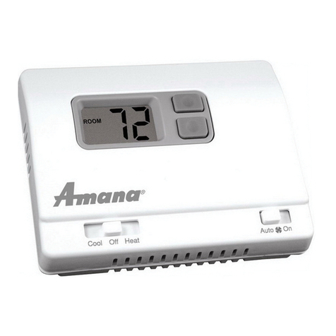
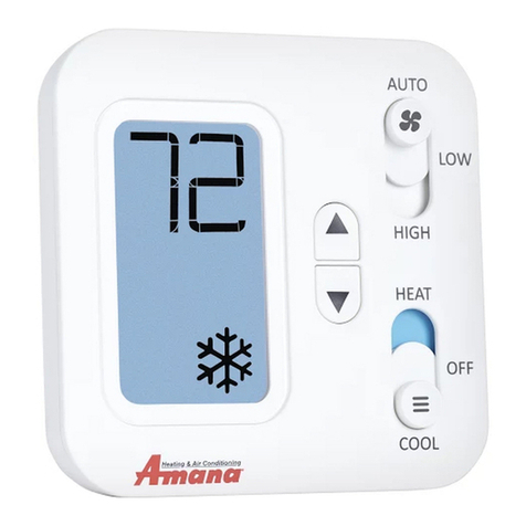
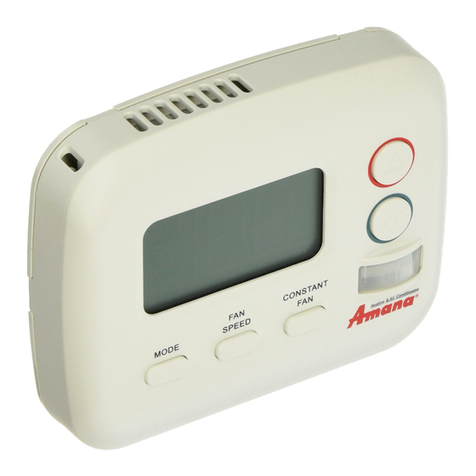
WIRELESS THERMOSTAT KIT (DSA01NM)
INSTALLATION INSTRUCTIONS
9/2015
IO-908A
Thermostat
Due to policy of continued product improvement, the right is reserved to change specifications and design without notice.
Heat in
g
& Air Co ndit io nin
g
®
A
5151 San Felipe, Suite 500 • Houston, TX 77056
www.amana-ptac.com
© Copyright 2015 Go o d m an Co m pan y, L. P.
is a registered trademark of Maytag Corporation or its related companies and is used
under license to Goodman Company, L.P., Houston, TX, USA. All rights reserved.
ATTENTION INSTALLING PERSONNEL
As a professional installer you have an obligation to know the
product better than the customer. This includes all safety
precautions and related items.
Prior to actual installation, thoroughly familiarize yourself
with this Instruction Manual. Pay special attention to all
safety warnings. Often during installation or repair it is
possible to place yourself in a position which is more
hazardous than when the unit is in operation.
Remember, it is your responsibility to install the product
safely and to know it well enough to be able to instruct a
customer in its safe use.
Safety is a matter of common sense...a matter of thinking
before acting. Most dealers have a list of specific good
safety practices...follow them.
The precautions listed in this Installation Manual are in-
tended as supplemental to existing practices. However, if
there is a direct conflict between existing practices and the
content of this manual, the precautions listed here take
precedence.
RECOGN I ZE THI S SYM BOL
AS A SAFETY PRECAUTI ON.
The following installation instructions are for a typical
installation.
Please contact your PTAC salesperson for additional assis-
tance and explanation prior to ordering materials or cutting
openings.
1. ANTENNA INSTALLATION FOR DSA01NM KIT
An antenna must be installed on the digital PTAC to allow
operation of the DSA01NM remote RF thermostat.
PREPARATION
1. Disconnect power to the unit by unplugging the power
cord at the wall outlet or subbase, or disconnect power
at the fuse box or circuit breaker.
2. If the cabinet front is screwed to the chassis, remove
the 1/4” screw (or screws). See following figure.
Radio - Non Mesh
Antenna
2
Front Mounting Screw
accessed
through louvers.
3. Remove cabinet front from chassis by tilting the bot-
tom of the front forward, lifting slightly up and for-
ward.
4. Mount the antenna as high up on the control panel as
possible and as far to the right as possible in a location
that will not interfere with the reinstallation of the PTAC
polymer room front. Mark holes for screw location. Re-
move antenna housing and drill two 1/8” holes where
marked. Some units may have the holes already pre-
drilled in the correct location.
Wire
ANTENNA Mounting
5. Remove antenna cable and route cable through open-
ing in bottom of antenna housing.
6. Mount antenna housing with two screws as shown in
figure. (NOTE: The Amana®brand logo should be in
the lower right hand corner).
7. Plug wire harness from antenna into the white connec-
tor housing on the control board to the right of the
master switch, being careful not to bend and/or break
the wires when you connect the cable to the PTAC.
Gently push the connector into place by pushing on the
edge of the connector with your thumb nails. Avoid
pushing directly on the wires. The wire has a small
clasp that must be oriented to the front to slide into
the white housing properly.
8. Restore power to the PTAC unit.
9. Reinstall the polymer room cover.
NOTE: The LED must be oriented at the top o f t h e a n t e n n a
housing (the Amana®b r a n d l o g o w i l l b e o n t h e l o w e r r i g h t )
for proper unit operation.
2. THERMOSTAT INSTALLATION FOR DSA01NM
KIT
NOTE: An antenna must be installed on the digital PTAC
unit for the DSA01NM thermostat to be operable.
1. Select thermostat mounting location about five feet
above the floor, on an inside wall, out of direct sun-
light, away from sources of radiant heat (lamps, fire-
places, heating and air conditioning equipment, etc.),
away from windows or door to the outside, and avoid
areas with poor air circulation.
Ensure location is out of the path of foot traffic where
a person might accidentally bump into the thermostat
and damage the device but is visible and convenient
for the room guests to locate and operate.
2. Remove thermostat from mounting plate by pulling
apart at the bottom of the thermostat about 1”, and
slide thermostat up to release from the top of the
mounting plate.
3. Place thermostat mounting plate against the wall at
desired location and mark placement of mounting
holes. Make sure the UP arrow is pointing up on the
mounting plate.
4. When mounting, drill a 3/16” hole and tap plastic an-
chor into wall.
5. Screw mounting plate to the wall.
6. Install four (4) AA batteries (included) into the back of
the thermostat. Terminals are marked “+” and “-” for
polarity.
7. Prior to attaching the thermostat body to the wall plate,
follow the steps on page 3 of this document for bind-
ing the thermostat to the antenna. When these steps
are completed and the thermostat has been bound,
continue with verifying the unit’s operation.
8. Once the binding process has been completed and the
operation process has been verified, install the
DSA01NM thermostat to the wall plate by aligning the
top two tabs of the thermostat to the top two slots on
the mounting plate. Once the two tabs are aligned
with the two slots, press slightly downward so the tabs
fall into the slots. Press the bottom of the thermostat
toward the mounting plate until the bottom fasteners
snap securely into place.
NOTE: Do not install the thermostat on the wall plate until
the binding process has been completed and the operation
has been verified.
3
NOTE: The DSA01NM antenna is not designed to function
with an occupancy sensor (DD01x) or in an RF mesh. If you
require an energy management system or web based moni-
toring, you must install a DT01G RF wireless antenna (sold
separately).
3. BINDING OF RF DEVICE
RF TRANSMITS THROUGH WALLS.
The wireless device, DSA01NM, must be bound to the PTAC
for proper in-room communication. Ensure the PTAC unit is
powered but in the OFF position.
1. Press and hold OFF button on the PTAC until appears.
2. Press and then immediately release the white tactile
button on the back of the DSA01NM thermostat.
should now be displayed on the PTAC LED display. If
does not show on the display in 1-2 seconds, then press
and release the white button a second time. When
appears, press the OFF button on the PTAC to exit the
binding mode.
After the PTAC has finished a diagnostic review and
the LED display is back to a blank screen, proceed to
test the thermostat operation. See the following
DSA01NM GENERAL FUNCTIONS.
WHITE
TACTILE
BUTTON
DSA01NM GENERAL FUNCTIONS
The MODE button, located in the far left corner of the
thermostat, allows the user to choose between off cool and
heat positions.
1. The first push on any button on the thermostat turns
the backlight on.
2. The second push of the MODE button will then allow
the user to cycle through the modes of desired opera-
tion: OFF, COOL or HEAT.
NOTE: What you change on one device will update to the
other.
3. If the thermostat is functioning properly, mount the
thermostat body on the previously installed wall
plate.
4. CONFIGURATION
The PTAC control will automatically self-configure to work
with the wall thermostat (DSA01NM Kit) if installed and
bound.
4
NOTE: This equipment has been tested and found to comply with
the limits for a Class B digital device, pursuant to Part 15 of the
FCC Rules. These limits are designed to provide reasonable
protection against harmful interference in a residential
installation. This equipment generates, uses and can radiate
radio frequency energy and, if not installed and used in
accordance with the instructions, may cause harmful
interference to radio communications. However, there is no
guarantee that interference will occur in a particular installation.
If this equipment does cause harmful interference to radio or
television reception, which can be determined by turning the
equipment off and on, the user is encouraged to try to correct
the interference by one or more of the following measures:
- Reorient or relocate the receiving antenna.
- Increase the separation between the equipment and
receiver.
- Connect the equipment into an outlet on a circuit
different from that to which the receiver is connected.
- Consult the dealer or an experienced radio/TV technician
for help.
NOTE: To comply with FCC RF exposure requirements in section
1.1307, a minimum separation distance of 20cm (8 inches) is
required between the equipment and all persons.
This equipment is authorized for use under the United States
Federal Communication Commission Rules and Regulations,
Code of Federal Regulations Chapter 47 part 15 and must be
installed in accordance with the instructions provided in
this document. Failure to install or operate this equipment as
instructed in this document could void the user’s authority
to operate the equipment. This equipment contains no user
serviceable parts. Any modification or repairs to the inter-
nal components or to the antenna configuration of the equip-
ment without the express written consent of Everex Com-
munications, Inc., could void the user’s authority to oper-
ate the equipment.
Due to policy of continued product improvement, the right is reserved to change specifications and design without notice.
5151 San Felipe, Suite 500 • Houst on, TX 77056
www.amana-ptac.com
© Copyright 2015 Goodman Company, L.P.
is a registered trademark of Maytag Corporation or its related companies and is used
under license to Goodman Company, L.P., Houston, TX, USA. All rights reserved.

Other Amana Thermostat manuals

Amana 2246002 General instructions

Amana

Amana 2246002 General instructions

Amana 2246003 General instructions

Amana

Amana 2246003 General instructions

Amana 2246008 User manual

Amana

Amana 2246008 User manual

Amana DT01* User manual

Amana

Amana DT01* User manual

Amana MMW-2 User manual

Amana

Amana MMW-2 User manual

Amana TSTATA4271GT User manual

Amana

Amana TSTATA4271GT User manual

Amana 2246007 General instructions

Amana

Amana 2246007 General instructions

Amana PTAC DS02G-H User manual

Amana

Amana PTAC DS02G-H User manual

Amana DS01E User manual

Amana

Amana DS01E User manual

Amana PHWT-A200 User manual

Amana

Amana PHWT-A200 User manual

Amana 2246008 General instructions

Amana

Amana 2246008 General instructions

Amana PHWT-A100C User manual

Amana

Amana PHWT-A100C User manual

Amana DT01* User manual

Amana

Amana DT01* User manual

Amana 2246007 User manual

Amana

Amana 2246007 User manual

Amana PHWT-A150H User manual

Amana

Amana PHWT-A150H User manual

Popular Thermostat manuals by other brands

Conrad Electronic 61 06 29 operating instructions

Conrad Electronic

Conrad Electronic 61 06 29 operating instructions

Riello Hi, Comfort 100 installer and user manual

Riello

Riello Hi, Comfort 100 installer and user manual

Robertshaw 9615 user manual

Robertshaw

Robertshaw 9615 user manual

HOTOWELL HTW-WF01-FC Series manual

HOTOWELL

HOTOWELL HTW-WF01-FC Series manual

OEM BYC07HE user manual

OEM

OEM BYC07HE user manual

aldes ALD-5404 Installation, specification and settings

aldes

aldes ALD-5404 Installation, specification and settings

TXU Energy iThermostat user manual

TXU Energy

TXU Energy iThermostat user manual

PNI CT25PE user manual

PNI

PNI CT25PE user manual

DAY Useful Everyday 73365 instruction manual

DAY Useful Everyday

DAY Useful Everyday 73365 instruction manual

Honeywell CM900 installation guide

Honeywell

Honeywell CM900 installation guide

TCS SuperSTAT Series Configuration guide

TCS

TCS SuperSTAT Series Configuration guide

Grasslin thermio essential H Brf operating manual

Grasslin

Grasslin thermio essential H Brf operating manual

Siemens RDS120 manual

Siemens

Siemens RDS120 manual

HAI Omnistat RC-120 installation manual

HAI

HAI Omnistat RC-120 installation manual

Rollei Smartes 45000 manual

Rollei

Rollei Smartes 45000 manual

ESI ES2247B User and installation instructions

ESI

ESI ES2247B User and installation instructions

HOTOWELL HTW-MT06 Series Installation and operation manual

HOTOWELL

HOTOWELL HTW-MT06 Series Installation and operation manual

Blaufoss Smartbox SOFTLINE installation guide

Blaufoss

Blaufoss Smartbox SOFTLINE installation guide

manuals.online logo
manuals.online logoBrands
  • About & Mission
  • Contact us
  • Privacy Policy
  • Terms and Conditions

Copyright 2025 Manuals.Online. All Rights Reserved.