microbike KT-LCD3 User manual
KT-LCD3 eBike Display User Manual V1.0
Dear customer, please read this manual before you use KT-LCD3 instrument. The manual will guide you use the
instrument correctly to achieve a variety of vehicle control and vehicle status display.
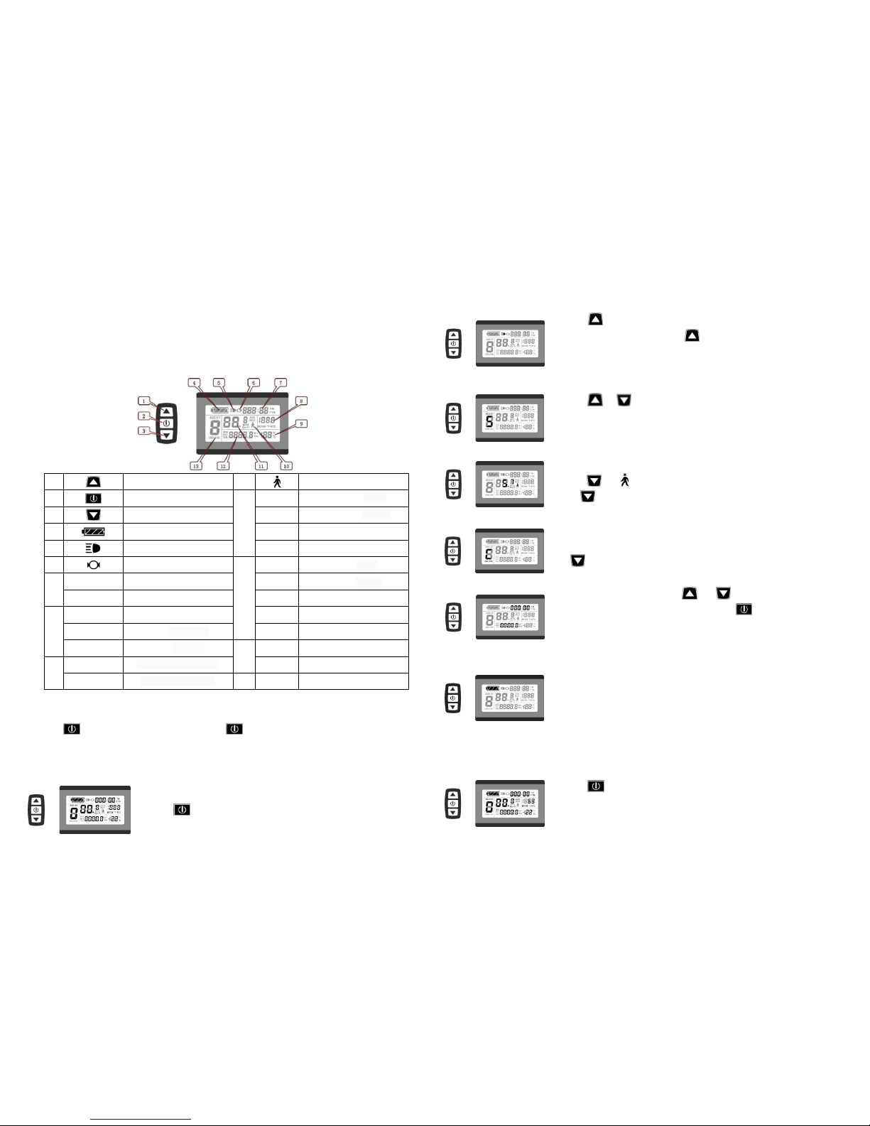
Functions and Display
Instruments using the structure form of instrument body portion and the operation buttons are designed separately.
1
UP Button
10
6Km/H push power assist
2
SW Button
11
Km/H
Riding speed(metric)
3
DOWN Button
MPH
Riding speed (imperial)
4
Battery capacity indicator
MXS
Single maximum speed
5
Backlight and headlights
AVS
Single average speed
6
The brake display
12
Km
Distance(metric)
7
TM
Single trip time
Mil
Distance (imperial)
TTM
Total trip time
DST
Trip distance
8
MOTOR W
Power display
ODO
Total distance
MOTOR ℃
Motor temperature
VOL
Battery voltage
MOTOR ℉
Motor fahrenheit
13
ASSIST
Pas level
9
℃
Environment temperature
CRUISE
Cruise
℉
Environment fahrenheit
Operation
1. ON/OFF
Hold button long to turn on the power, and hold long for a second time to turn off the power. When the
motor stops driving and when the e-bike is not used for a consecutive 5 minutes, it will automatically shut down and turn off
the motor power supply.
2. Display 1
Hold button to start up and enter display 1.
2.1 Turn on backlight and headlights
Hold long to turn on backlight and headlights (the controller should have
headlight drive output function); hold long again to turn off the backlight and
headlights.
2.2 Assist ratio gear (ASSIST) switch
Hold or shortly to switch 1-5 file gear. Gear 1 is for the minimum power,
gear 5 is for the highest power. Each startup will automatically restore the gear shutdown
last time(the user can set randomly). Gear 0 is without booster function.
2.3 6Km/H assist promotion function
Hold and flashes,the vehicle drives at the speed not more than 6Km /h.
Release button,the function is invalid.
2.4 Cruise function
After the cruise function is turned on, the trip riding speed is greater than 7km/ h,
hold long and enter cruise, the CRUISE lit. Brake or hold any button to cancel.
2.5 Display and delete of single Data
After power on for 5 seconds, hold and at the same time, single trip
riding time (TM) and single trip distance (DST) flash, hold button shortly, the
content of both is cleared. If failed holding the button within 5 seconds, it will
automatically return the display interface after 5 seconds, original content is preserved.
2.6 Battery capacity indicator display
The meter can automatically identify 24V, 36V, 48V battery capacities when it is
supporting use with the specified controller. When the battery capacity is over 70%, the
four power displays of the meter are lit, when the battery capacities drop, the four power
displays are off in order, when the power capacity is less than 15%, the four power
displays are totally turned off. When the controller is power off due to voltage shortage, the power display frame flashes,
indicating the vehicle has been in voltage shortage and waiting for shutdown currently.
3. Display 2
Hold button shortly in display 1 to enter display 2. Toal trip time (TTM) and
total distance (ODO), single average speed (AVS), motor operating temperature

(MOTOR ℃)are shown on display 2.
In the riding mode after 5 seconds, display 2 automatically returns to display 1, and the originalmotor power (MOTOR W)
display is replaced with motor operating temperature display (MOTOR ℃) display (the internal motor should be equipped
with the temperature sensor and the output of temperature detection signal).
4. Display 3
Hold button shortly in display 2 to enter display 3. Single maximum speed
(MXS), Real-time Voltage (VOL) are shown on display 3.
In the riding condition, 5 seconds later, a single maximum speed (MXS) display
automatically returns to the real riding speed (Km/H).
5. In display 3, hold button shortly and the display will re-enter display 1.
6. Hold button to turn off the display and the power supply of controller.
7. Automatically prompt interface
7.1 Error Code display Error Code Definition
01_info Throttle Abnormality
03_info Motor Hall Signal Abnormality
04_info Torque sensor Signal Abnormality
05_info Axis speed sensor Abnormality(only applied to torque Sensor)
06_info Motor or controller has short circuit Abnormality
Electronic control system failure will display (flashing) fault code. Once the fault was removed, it automatically exits
from the fault code display interface.
7.2 Motor temperature alarm
When the motor temperature (the internal motor should be equipped with the temperature sensor and the output of
temperature detection signal) is over the warning value, MOTOR ℃(℉) flashes to alarm at any display, meanwhile the
motor controller will offer the appropriate protection to motor.
General Project Setting
1. Set maximum riding speed
After power on for 5 seconds, hold and at the same time, maximum
riding speed Km/H and MXS flash, hold or shortly to set the maximum riding
speed (default 25Km/H). Hold button shortly and go to the next parameter
settings.
2. Wheel diameter setting
The wheel diameter will be set after finishing setting the maximum riding speed,
wheel diameter specifications flashes. Hold or shortly to set the specifications of wheel diameter. Select the
range 6,8,10,12,14,16,18,20,22,24,26,700c and 28 inches. Hold button shortly and go to the next parameter settings.
3. Set the metric units
The metric units will be set after finishing setting wheel diameter, Km/H and Km flash.
Hold or shortly and select the three metric units of speed, mileage, and
ambient temperature in synchronization.
Display
Metric
Imperial
Riding speed
Km/H
MPH
Total distance
Km
Mil
Environment temperature
℃temperature
℉fahrenheit
4. Km/H and Km stop flash after metric unit setting is completed. Hold button shortly again to re-enter the
maximum riding speed setting interface; or hold button long to exit from setting environment of routine projects and
save the setting values, returning to display 1.
5. Exit from routine project setting
All three routine project settings can exit from the setting environment and return to the display if hold button
long after each setting is completed, meanwhile the setting values are saved.
Under each setting interface, if the button failed holding for more than 1 minute, it will automatically return to display 1,
and the setting value is invalid.
Outline Drawings and Dimensions
1. Dimensions of main instrument body 2. Mounting dimensions of double brackets
3. Dimensions of button box 4. Wiring diagram
Prepared by Suzhou Kunteng Electronics Co., Ltd.


