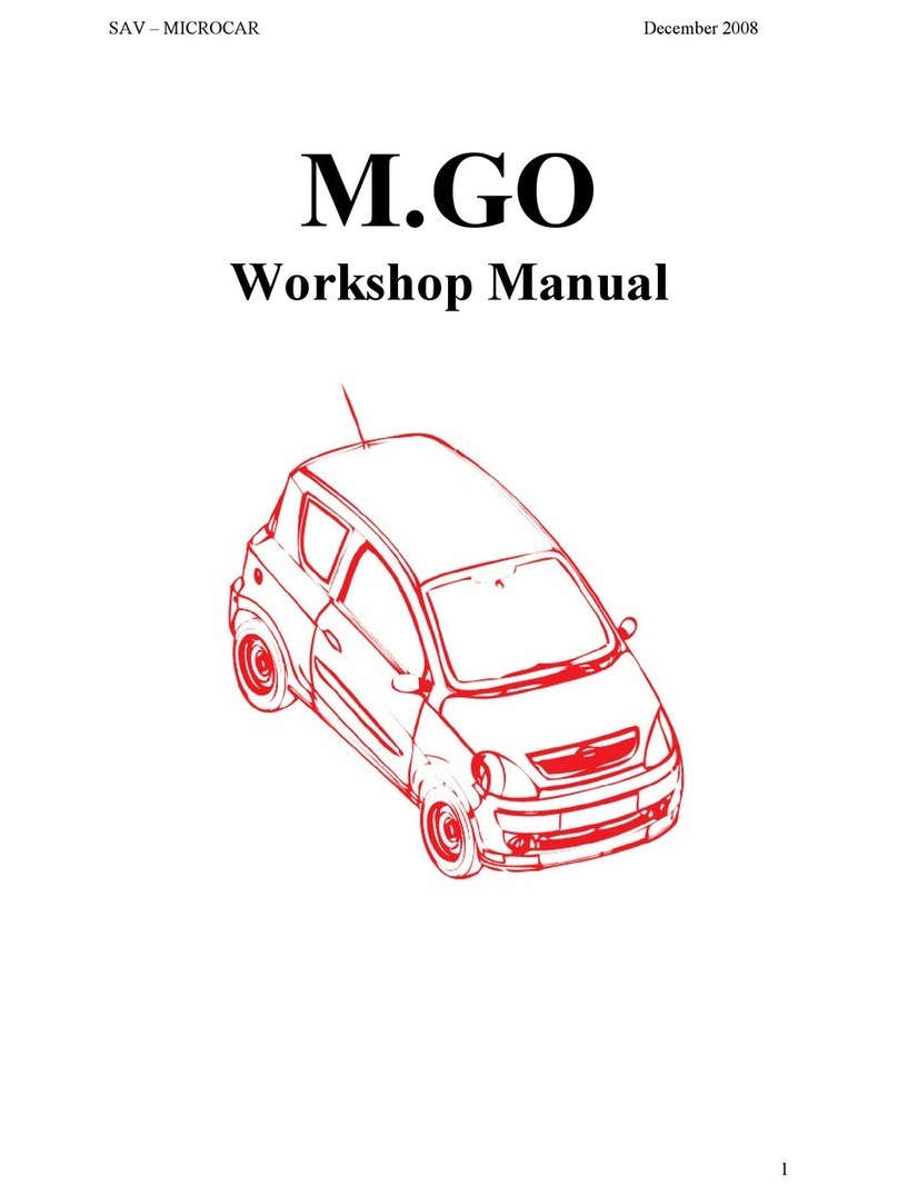
Microcar MC1 User manual

MICROCAR
WORKSHOP TECHNICAL MANUAL

2
INTRODUCTION
This manual has been made to help you in the repairing and maintenance
operations. It contains all the details about the car and the indications for the fitting
and unfitting.
We advice you to read very carefully the paragraphes linked to your interventions.
Our After Sales department stays at your disposal for any further information.
With the aim of improving its models, MICROCAR specifies this whole brochure is not contractual
and keeps the right to change (without warning) its car specifications.
Concept / ATTRAITS GRAPHIC 05 49 71 20 62

3
SUMMARY
Pages
SUPPLYING .................................................... 4
IDENTIFICATION ............................................ 5
LIFTING ...........................................................5
TECHNICAL CHARACTERISTICS ........... ......6
D...OOR REMOVAL..............................................8
INTERIOR DOOR MAINTENANCE ................... 9
REAR DOOR ......................................... ..........14
FRONT BUMPERS REMOVAL.................. ......19
FRONT WINGS REMOVAL..............................20
DOOR HINGES REMOVAL............................. 22
BONNET REMOVAL ...................................... 22
OPTI.C LIGHTS REMOVAL............................ 22
BACK BUMPERS REMOVAL ........................ 23
HATCHBACK OPENING SWITCH REMOVAL.24
INTERIORTRIM REMOVAL........................... 25
SAFETY BELT RETRACTOR REMOVAL..... 27
TR.IM ROOF CHANGING............................... 27
D.ASHBOARD REMOVAL............................... 29
REVERSER LEVER REMOVAL.................... .35
R.EAR QUARTER PANEL REMOVAL........... 36
BACK WING REMOVAL ................................ 37
WINDSCREEN REMOVAL...............................42
ROOF REMOVAL ........................................... 44
B..ODY SIDE REMOVAL................................. 46
SOU..NDPROOFING FLOOR KIT GLUING.... 50
SOUNDPROOFING KIT APRON GLUING.....51
ABS REPAIRING............................................. 52
ALUMINIUM REPAIRING ............................. 53
FLOOR REPAIRING ...................................... 54
CARPET REPAIRING .................................... 55
Pages
P.AINTING COMPONENTS AND REPAIRING...... ..56
SOUNDPROOFING ENGINE PANEL REMOVAL... 58
TRANSMISSION REMOVAL.................................... 60
TRANSMISSSION GAITER CHANGING................................ 61
VARIATOR REMOVAL ............................................ 62
RECEPTOR PULLEY REMOVAL............................. 66
RE.VERSER DRIVE AXLE REMOVAL....................... 68
RE..VERSER DRIVE AXLE BOX REMOVAL............... 71
STARTER REMOVAL .............................................. 74
ENGINE REMOVAL ................................................. 75
ENGINE CRADLE REMOVAL................................. 76
ENGINE.CRADLE EQUIPEMEMENT...................... 78
BR.AKE PAD REPLACING....................................... 88
FRONT HUB BEARING REPLACING ..................................90
FRON T HUB BEARING REPLACING .................................94
STEERING............................................................... 96
BRAKING SYSTEM BLEEDING ....................... ......99
PARKING BRAKE REGULATING ....................... 100
BACK EXHAUST ................................................... 101
ELECTRIC SYSTEM ............................................ 102
FUSES ................................................................... 103
LOAD VOLTAGE CONTROL ................................ 104
FRONT WINDSCREEN ......................................... 105
INSTRUMENT ADJUSTMENT .........................107
VENTILATION CONNECTING .............................. 108
ENCLOSED ........................................................... 109
ELECTRIC PLANS
TECHNICAL INFORMATION N°247
TECHNICAL INFORMATION N° 249

4
SUPPLYING
Engine oil
Box oil
Brake liquid
Coolant
liquid
Windscreen washer
QUANTITIES
1,50 liter
0,50 liter
3 liters
The level in the
radiator must be 1cm
above the radiator fins
1 liter
SUPPLYING TYPE
CERAMIC SYMBOL 5W40
TRANS EPA 80W90
DOT 4 blue ribbon
TRANSFLUID
Windscreen washer IGOL

5
LIFTING
CAR IDENTIFICATION
With a workshop jack, use only the lifting points as shown below.
NOTA : Take care to insert
a wood block between the
jack and the car.
FRONT :
Under the carcase of the body
BACK
Under the carcase of the body
Constructor plate
The constructor plate is situated inside the car
on the front right pillar (under the instrument
panel below the passenger seat). 1-Vin number
2-Homologation number
3-Painting reference number
vin number
The vin number is put on the right side member
near the passenger seat.
1 2 3

6
Engine
Brand ............................................................................ LOMBARDINI
Type ................................................................................ LDW 502/M3
Cycle ............................................................................... Diesel (4 times)
Cubic capacity......................................................................... 505 cm3
Cylinders ............................................................................. 2in lines
Coolant ........................................................................... Liquid
Used fuel ......................................................................... Diesel
Feed type ........................................................................ Injection (electric pump)
Fuel tank capacity ........................................................... 16 liters
Electric feed ................................................................... Alternator
Movement transmission
Gearbox with continual variation automatic transmission with reverse and forward gear.
Automatic centrifugal clutch.
Maximum speed authorized.
Suspension
Double action, hydraulic shock absorbers with front and back helical springs
Direction
Direction type : rack (without maintenance)
Steering diameter :8.20m
Braking
Service brake : hydraulic double circuit which acts on front and back wheels
Parking brake : mechanical, it acts on the 2 back wheels
Wheels
Sizes : 145/60R13 65S
Wheels pressure:Front = 1,6 bar.
Back = 1,8 bar.
Body
Carcase in aluminium mechanical soldered profiles
Floor and apron in SANDWIFORM cellular composite panels
ABS trim
Weight and size
Discharged weight : 348 kg.
Running weight : 400 kg.
Total athorized loaded weight : 620 kg.
TECHNICAL CHARACTERISTICS

7
SIZES : (in mm)

8
To take out the door, open the bonnet and unplug
the battery using the red speed disconnecting cable terminal
(+).
Take off the ducts of the body pillar, take out and unplug
the 2 connectors of the window winder beam and central locking
✱.
✱It depends on the version
DOOR REMOVAL
Hold the door with the handle and put the 2 fixing screws
of the hinges.
(Set screw 7 N/m)
The fitting of the door is made at the reverse from the
removal operations.
Before intervening on any components of the
electric setting, unplug the positive cable (red)
of the battery.

9
Take the fixing screw out of the interior door opening
switch.
INTERVENTIONS
ON THE INTERIOR DOOR
EQUIPEMENTS
Take out the cap of the handle.
With a screwdriver, unclip the opening tip on the
handle.
Take out the command.
Take off the trim starting in a conner
(fixed with a VELCRO strip)
We advice you to hold the sticker VELCRO
to avoid that it comes undone.

10
Take out the interior and exterior lock.
With a cuciform screwdriver, unscrew the fixing screw and take off
the plastic handle.
Take out the 2 fixing screws of the exterior lock
(key 6 sections).
LOCK AND CYLINDER LOCK DOORS
NOTA:to make the following operations easier, we advice
you to take the door out.
(see chapter "door removal" page 8)
Take out the central locking rod inside the door.
Take out the cylinder lock,pulling up its fixing fork and taking
off thecylinder lock from its place.

11
CENTRAL LOCKING ENGINE
Thanks to a drilling machine (drill Ø 5) take out the 2 rivets of
the fixing of the central locking engine mounting plate.
Take out the plate and engine and unplug the electric
beam.
Take off the 2 enginefixing screws.
DOOR POCKET
Withe a screwdriver, take off the 3 black plastic rivets
and take out the door pocket.
DOOR WINDOW
Take out the 4 fixing screws of the door frame, 2 screws at the front
and 2 at the back.
To take out the door window, it is better that it goes up
at the maximum.

12
Lean slightly the window of the interior of the door
to take it out of the fixing axle.
Take out the window pulling it up.
Take off the joints.
Take out the door frame pulling it up.
Undo the fixing axle of the window.

13
ELECTRIC WINDOW WINDER
Take out the inferior fixing screw of the
window winder runner.
Take out the superior fixing screw of the window winder runner.
Take off the 2 screws of the window winder engine.
Unplug the electric beam and take out the window winder
of the interior door.
HINGE REINFORCEMENT PLATE
With a drilling machine (drill Ø 5) take out the 2 fixing rivets
of the hinge reinforcement plate.
Take off the beam and take out the plate.
All the reassembly operations of the interior door elements are made at the
reverse from the removal operations.

14
REAR DOOR
REAR DOOR REMOVAL
Unplug the battery using the red speed disconnecting cable
terminal (+).
Remove the ball joints of the 2 gas compass.
Take off the hatchback.
The fitting of the hatchback has to be made at the reverse from
the removal operations.
3rd PARKING LIGHT
After having unplugged the battery, take out the 2 fixing screws
of the hatch of the rear window.
Open the hatchback.
Unplug the hatchback electric beam, behind the right side
trim and take it out of the trim.
Hold the hatchback and take off the 2 fixing screws of the
hinges on the body.
Nota: When fitting again, for a perfect waterproofness, put some
silicone joint in the places of the hinges fixing screws.

15
Take off the hatch.
Unplug the beam of the 3d parking light.
Take out the 2 fixing screws of 3d parking light.
Take off the 3d parking light.
After having taken out the 3d parking light, you will be able to
reach the defrosting back window beam.
NOTA: The electric beam inside the hatchback can't be dismantled,
it is assembled first in the factory.

16
BACK WINDSCREEN WIPER
After having unplugged the battery and taken out the hatch of
the back window (see paragraph "3d parking light" page 14)
take out the fixing nut of the wiper arm under the nut cover.
Take out the wiper arm and the nut cap.
Take out the M16 fixing nut of the windscreen wiper engine.
Take out the spacer and washer.
Take out the windscreen wiper engine from inside the
hatchback and unplug its beam.
The fitting is made at the reverse from the removal operations

17
PLATE LIGHT
After having unplugged the battery, thanks to a screwdriver,
undo the plate light and take it out from its place.
Unplug the beam from the light plate.
HATCHBACK HINGE
After having taken out the hatchback (see paragraph hatchback
removal), take off the fixing nut and take out the hinge.
(set screw 6N/m)
REAR DOOR BOX STABLE
Take out the 2 fixing screws from the box stable.
REAR DOOR
After having made all these operations, take out the glass section.
.

18
Loosen the 2 compass ball joints.
(Set screw when fitting again 4,2 N/m).
Take out the 2 ball joints with nuts and washers.
Unglue the window from the hatchback.
Use the piano rope given in the gluing window kit
(réf. 0 700 200).
Make the cable slided between the window and the hatchback
on all length.
Use the gluing kit (ref 0700200) taking care of cleaning the
surfaces which must be glued.
Apply the primary of the kit on all the length of the window
Apply the primary (réf. 1 002 818) on the ABS of the hatchback.
Take out all the wastes of the
previous gluing.
Be carefull not to damage the ABS of the hatchback.
The reassembly of the rear door is made at the reverse
from the removal operations.
It is necessary to put the primary on all the parts
which must be glued (windows and body).
Put a line of glue on the primary.
Fit again the window on the hatchback and fix it with
2 ball joints + washers + nuts (set screw 4,2 N/m)
Let dry during 6 hours before doing new manipulations
Some primaries can damage the ABS.
It is necessary to apply the primary 5 minutes
before gluing. This one keeps its efficiency during
72 hours at the maximum.

19
FRONT BUMPER REMOVAL
Open the bonnet and take out the superior soundproofing.
Thanks to a screwdriver, take out the 2 black plastic rivets
inferior fixing.
Take out the 2 black plastic rivets from the wings
Fall over the bumper to the front and make it turn around its
superior fixing pegs on the sealed beam units.
Take the bumper out of the superior fixing pegs.
Use the flexibility of the ABS bumper to make this operation.
Do not force or break the centring pegs of the
sealed beam units.
The fitting of the bumper is made at the reverse from
the removal operations.

20
FRONT WINGS REMOVAL
Take out the door.
Take out the front bumper (voir page 19).
Take off the gaiter nut cover which fixes the door mirror.
With a combination pliers, take out the plastic nut from the
door mirror fixing.
Take out the door mirror.
With a screwdriver, take out the black plastic rivet of the superior
fixing from the pillar wing.
Take out the black plastic inferior fixing rivet.
Table of contents
Other Microcar Automobile manuals
