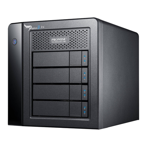
Microcomputer Systems MSC-9800H User manual

6/30/81-0P47-26
M~CROCOMPUTER
SYSTEMS
CORPORATION
MSC-98OOH
WiNCHESTER
DISC
STORAGE
SUBSYSTEM
USER'S
MANUAL
JUNE
1981
PRELIMINARY
104221
All manuals and user guides at all-guides.com
all-guides.com

SECTION
I
2
3
6/30/SI-0P47-27
TABLE
OF
CONTENTS
TITLE
GENERAL INFORMATION
1.1
Introduction
1.2
Description
INSTALLATION
2.1
Introduction
2.2 Unpacking and Inspection
2.3 Installation
Procedures
2.3.1
Setting
Line Voltage
2.3.2 Selecting Proper Fuse
2.3.3 Power Cord
2.4 Disc Drive Setup
2.4.1 Connecting
to
the
HP-85
2.4.2
Select
Code Switch
2.4.3 Device Address Switches
2.4.4 Installing Mass
Storage
ROM
OPERATING THE DISC DRIVE
3.1
Introduction
3.2 Overview
3.3
Controls
and Indicators
3.4 Power On
3.5
Usi
ng
the
Disc Drive
3.5.1 Accessing
the
Disc Drive
3.5.2 Working With Files
3.5.2.1
Create
Command
3.5.2.2
Cat
Command
3.5.2.3 Mass
Storage
Is
Command
3.5.2.4
Rename
Command
3.5.2.5 Copy Command
3.5.2.6 Purge Command
PAGE
3
3
3
3
5
8
9
9
9
9
12
14
14
14
14
16
16
17
17
i7
18
19
19
21
All manuals and user guides at all-guides.com

SECTION TITLE PAGE
4 SERVICE INFORMATION
4.1
How to Obtain Repair Service
21
4.2 General Shipping Instructions
21
4.3 Repair
Policy
21
APPENDICES
A ACCESSORIES 23
B ENVIRONMENTAL SPECIFICATIONS 24
C
LIMITED
90-DAY
WARRANTY
25
6/30/81-0P47-28
All manuals and user guides at all-guides.com

TABLE
2-1
2-2
6/30/81-0P47-29
TABLES
TITLE
FUSE
SELECTION
DEVICE
ADDRESS
SWITCH
PAGE
8
II
All manuals and user guides at all-guides.com

1.1
INTRODUCTION
SECTION I
GENERAL INFORMATION
The
MSC-
9800H Winchester
Disc
Storage System
(Figure
1-
I)
provides mass
storage
capabilities
for
the
HP-85
Computer.
The disc
drive
connects
directly
to
the
HP-85
and requires
only
the
Mass Storage
ROM.
The
ROM
provides
all
the
necessary
interface
control
so
that
the
disc
drive
and
the
HP-85
can
communicate.
This manual contains
all
the
information
that
the
user needs
in
order
to
install
and use
the
disc
drive.
For
a
detailed
description
of
the
Mass Storage
ROM
consult
the
following
HP
manual:
Mass Storage
ROM
Manual
HP
Number:
00085-90447
1.2
DESrnlPTION
The
MSC-
9800H has a
total
formatted
capacity
of
4.6 megabytes,
divided
into
four
sections. The
capacity
of
each
section
is
the
equivalent
of
the
capacity
of
an
8-inch,
double-sided
flexible
diskette.
From
the
user's
point
of
view,
the
MSC-9800H
operates
as
four
separate
flexible
disc
drives
controlled
by one
controller.
The
controller
addresses each
of
the
four
sections
of
the
disc
drive
as
a separate
flexible
disc
drive.
6/30/81-0P47
-1-
All manuals and user guides at all-guides.com

FIGURE
I-I
HP9800H
6/30/81-0P47
-2-
All manuals and user guides at all-guides.com
all-guides.com

SECTION 2
INST
ALLATION
2.1
INTRODUCTION
This
section
contains
the
information
that
is
necessary
in
order
to
prepare
the 9800H disc
drive
for
operation.
2.2 UNPACKING AND INSPECTION
The disc
drive
was
carefully
inspected,
both
electrically
and
mechanically,
before
the
factory
shipped
it.
Remove
the
drive
from
the
shipping
carton
and
carefully
inspect
the
unit
for
any physical damage
that
may
have
occurred
during
shipment.
If
you
find
any damage,
notify
your dealer
immediately
and,
also,
file
a
claim
with
the
carrier
involved.
Save
the
shipping
container
in
case
the
unit
must
be
returned
for
service
or
shipped
to
a new
location.
NOTE: THE MSC-9800H is a precision
device.
It
has been
built
to
withstand
normal handling.
Care must be
taken
not
to
drop
it
or
bump
it
hard. Evidence
of
excessive shock
wi
II
void
the
warranty.
2.3
INST
ALLATION PROCEDLRES
The
installation
procedures consist
of
the
following:.
setting
the
proper
line
voltage,
setting
the
device
address, and
connecting
the
HP-IB
cable.
2.3.1
Setting
Line
Voltage
7/7/8I-OP47
The
factory
configures
the
MSC-9800H
to
operate
at
a
line
voltage
of
120
volts
a.c.
at
a
frequency
in
the
range
of
47
to
63
Hertz.
If
the
current
installation
has
another
voltage,
then
the
line
voltage
setting
of
9800H
must
be
changed. The procedure
to
change
the
line
voltage
follows.
-3-
All manuals and user guides at all-guides.com

WARNING
Remove
the
a.c.
power cord from
the
service
outlet.
A sliding,
clear-plastic
cover above
the
a.c.
connector
on
the
rear
paneI serves
as a
safety
mechanism. Even
though
there
is
a
safety
mechanism
on
the
rear,
it
is
safer
to unplug
the
line cord.
I.
Remove
the
a.c.
power cord from
the
service
outlet
and from
the
rear
of
the
disc drive. See Figure
2-1.
2.
Slide
the
plastic
cover
at
the
side
of
the
line plug
connector
down all
the
way
so
that
the
cover
is over
the
line plug
connector.
3. Look
at
the
small
wafer
at
the
top
of
the
a.c.
line
connector.
The wafer
shows one
of
the
following numbers: 100,
120,
200, or 240; this number
is
the
voltage for which
the
disc drive
is
configured.
4.
If
the
number on
the
wafer
differs
from
the
voltage
available
at
the
installation,
remove
the
wafer
from
its
slot.
See
Figure
2-2.
5. The
wafer
has
the
numbers 100, 120, 200 and 240
on
both sides. Observe
the
number
that
corresponds
to
the
voltage
at
the
current
installation.
6. Position
the
wafer
so
that
the
number
that
corresponds
to
the
voltage
at
the
current
installation is visible and right side
up
at
the
left
side of
the
wafer.
7.Re-insert
the
wafer
in
its
slot,
making
certain
that
the
selected
number on
the
wafer
is still visible from
the
inserted
position.
I'KlTE
The disc drive is now configured
to
operate
at
the
voltage
at
the
current
installation.
No
frequency
conversion
is
necessary.
8. Slide
the
plastic
cover back over
the
wafer.
7/7/81-0P47
-4-
All manuals and user guides at all-guides.com

9.
Plug
the
a.c.
power
cord
into
the
a.c.
connector
at
the
rear
of
the
disc
drive.
This
completes
the
setting
of
the
line
voltage.
2.3.2
Selecting
Proper
Fuse
7/7/81-0P47
The
factory
ships
the
disc
drive
with
the
correct
fuse
for
120
volts.
For
operation
at
other
I
ine
voltages,
the
u~er
must
install
the
proper
fuse.
See
Figure
2-3
for
fuse
replacement.
FIGURE
2-1
REAR
PANEL
OF
MSC-9800t-t
DISC
DRIVE
-5-
All manuals and user guides at all-guides.com

FIGURE
2-2
VOLTAGE-SETTING
WAFER
6/30/81-0P47
-6-
All manuals and user guides at all-guides.com

FIGURE
2-3
REMOVING FUSE
6/30/81-0P47
-7-
All manuals and user guides at all-guides.com
all-guides.com

The fuse
receptacle
is
on
the
rear panel
of
the
disc
drive.
Table 2-1
lists
the
voltage
settings
and
the
proper fuse
ratings
for
the
voltage
settings.
TABLE
2-1
FUSE
SELECTION
LINE
VOLTAGE
SETTING
100
to
120
vac
220
to
240
vac
FUSE
RATING
(250V)
2 amperes
1ampere
To
install
or
replace
the
fuse,
first
disconnect
the
power
cord
from
the power
outlet.
I.
Remove the fuse by
pulling
out
the
fuse
lever.
2.
Push
the
proper fuse
into
the
clips
(see
Figure
2-3).
2.3.3 Power Cord
6/30/81-0P47
The power cord
that
the
factory
supplies
must
match
the
plug
requirements
of
your
areaLJf
the
.disc
drive
has
the
wrong
power
cord,
get
in
touch
with
your
local
dealer
or
sales
representative.
WARNING
Use
only
the
power
cord
specified
by
Microcomputer
Systems
for
your area.
If
it
is necessary
to
replace
the
power
cord,
the
replacement
must have
the
same
polarity
as
the
original.
This
warning must be observed;
otherwise,
a
safety
hazard
from
electrical
shock can
exist.
Also,
using
the
wrong
cord
can damage
the
disk
drive.
-8-
All manuals and user guides at all-guides.com

2.4 DISC DRIVE SETUP
After
the
power
requirements
have been taken
care
of,
the
disc
drive
is
ready
for
connection
to
the
HP-85.
The
following
paragraphs describe
the
necessary connections and
settings.
2.4.1 Connecting
to
the
HP-85
The user
must
use
an
HP-IB
Interface
Module, model
HP
82937
A,
in
order
to
connect
the
disc
drive
to
the
HP-85
computer.
Hewlett-Packard
supplies
the
Interface
Module. The
following
procedure shows how
to
connect
the
disc
drive
to
the
HP-85
computer.
I.
Turn
off
the
power
on
both
the
disc
drive
and
the
HP-85
computer.
2.
Plug
the
HP-IB
Interface
Module
into
an
I/O
port
at
the
rear
of
the
HP-85.
3.
Refer
to
Figure
2-4
and plug
the
connector
of
the
HP-IB
Interface
Module
into
the
mating
HP-IB
connector
at
the
rear
of
the
disc
drive.
2.4.2 Select Code
Switch
The
Hewlett-Packard
factory
sets
the
select
code
of
the
HP-IB
Interface
Module.
If
you
must
change
the
setting
of
the
select
code, consult
the
manual
for
the
HP-IB
Interface
Module.
2.4.3
Device
Address Switches
6/30/81-0P47
Each
device
that
connects
to
the
HP-85
through
the
HP-85
Interface
Module has an address
that
identifies
it.
The
Interface
Module can
accept
up
to
eight
devices, each
of
which
must
have a
separate address. On
the
disc
drive,
the
device
address is
set
using
the
DEVICE
ADDRESS switches on
the
rear
panel
of
the
disc
drive.
Table
2-2
lists
the
settings
of
the
DEVICE
ADDRESS
switches.
-9-
All manuals and user guides at all-guides.com

FIGURE
2-4
CONNECTING
HP-IB
6/30/81-0P47
-10-
All manuals and user guides at all-guides.com

6
Open
Open
Open
Open
Clsd
Clsd
Clsd
Cisd
NOTE
Only
switches 6, 7 and 8
of
the
device address
are
used.
Switches I through 5 must
be
set
to
the
OPEN position
at
all
times.
TABLE
2-2
DEVICE
ADDRESS
SWITCH
SWITCH NUMBER
7 8
Open Open
Open Clsd
Clsd Open
Clsd Clsd
Open Open
Open Clsd
Clsd Open
Clsd Clsd
Value
0
I
2
3
4
5
6
7
Before
shipping
the
disc
drive,
the
factory
sets
the
device
address
to
3.
If
you need
to
change the
device
address,
turn
off
the
power
to
the
drive
by
setting
the
power
switch
on
the
rear
panel
to
OFF.
It
is
very
important
that
you
turn
off
the
power
before
changing
the
address switches.
6/30/81-0P47 -11-
All manuals and user guides at all-guides.com

Set a
switch
section
to
OPEN by Jsing a
pointed
object
to
press
the
lower
portion
of
the
rocker
to
OPEN. Set a
switch
section
to
CLOSED by pressing
the
upper
portion
of
the
rocker
to
CLOSED.
In
the
table
CLOSED is
indicated
by CLSD (see
Figure
2-5).
2.4.4
Installing
Mass Storage
ROM
6/30/81-0P47
In order
to
use
the
9800H disc
drive
with
the
l
HP-85
computer,
the
HP-85
Mass Storage
ROM
must be
installed
in
the
HP-85
computer.
You
must
first
install
the
ROM
in
the
ROM
Drawer.
Then you
must
install
the
ROM
Drawer
in one
of
the
four
I/O
ports
of
the
HP-85
computer.
For
instructions
in
installing
the
ROM
and
the
ROM
Drawer,
consult
the
HP 82936A
Rom
Drawer
Instruction
Sheet and
the
HP-85
Owner's Manual and
Programming
Guide. The
HP-85
Mass Storage
ROM
Manual
contains
complete
instructions
for
using
the
ROM
with
disc
drives.
-12-
All manuals and user guides at all-guides.com
all-guides.com

FIGURE
2-5
SETTING
DEVICE
ADDRESS
SWITCHES
6/30/81-0P47
-13-
All manuals and user guides at all-guides.com

3.1
INlRODUCTION
SECTION
3
OPERATING
THE
DISC
DRIVE
This section discusses
the
operation
of
the
MSC-9800H Winchester
Disc
Storage System,
referred
to
as
the
disc
drive.
Before
reaching
this
point,
the
user should have
installed
the disc
drive
as
described in Section
2.
3.2
OVERVIEW
The storage
capacity'
of
the
disc
drive
is 4.6 megabytes;
the
HP-85
computer
sees
this
capacity
as
four
separate storage
capacities
of
approximately
1.15
megabytes,
the
equivalent
of
an
eight-inch,
double-sided
flexible
disc.
These
separate storage
capacities
are designated volumes in
the
same manner
that
individual
flexible
disc drives
are;
these volumes
initially
have
the
factory-assigned
labels
of
DO,
0 I,
02
and
03,
and each has
its
own
directory.
All
volumes,
however,
have
the
same
HP-IB
(device) address.
3.3 CONlROLS
AND
II'DICA
TORS
The disc
drive
has
two
controls
and one
indicator
that
the
user
must
be aware
of.
The
two
controls,
located
on
the
rear
panel,
are
the
power
switch
and
the
device-address
switch.
Both
of
these
controls
are
discussed in Section 2.
The
indicator,
the
drive
accessed
light,
is on
the
front
panel;
it
lights
whenever a
volume
is accessed (see
Figure
3-1).
3.4 POWERON
Before
turning
on
the
disc
drive,
make
certain
that
all
connections have been
made.
Refer
to
Section 2,
Installation
if
necessary.
Locate
the
power
switch
on
the
rear
panel and set
it
to
the
ON
position.
The
disc
drive
requires
about
20
seconds
after
the
application
of
power
before
it
is ready
for
operation.
Turn
the
disc
drive
on
before
applying power
to
the
HP-85.
7/7/81-0P47 -14-
All manuals and user guides at all-guides.com

FIGURE
3-1
DRIVE
ACCESSED
LIGHT
6/30/81-0P47 -15-
All manuals and user guides at all-guides.com

3.5
USING
THE
DISC
DRIVE
The manual
for
the
Mass Storage
ROM
contains
all
the
information
that
the
user needs
to
operate
the
disc
drive.
In
that
manual,
all
references
that
are
made
to
individual
flexible
disc
drives
are
applicable
to
an
individual
volume
on
the
MSC-9800H
disc
drive.
The
following
paragraphs in
this
section
give
exarnples
of
some
of
the
ways you can use
the
disc
drive.
NOTE
Some commands
like
COpy
and
PACK
can
take
several
minutes
to
complete.
Do
not
press RESET
during
the
execution'
of
these
commands:
data
will
be
lost.
3.5.1 Accessing
the
Disc
Drive
7/7/81-0P47
The user can access
the
disc
drive
in
one
of
two
ways: using
the
mass
storage
unit
specifier
(msus)
or
the
volume
label
for
a
specific
volume.
These
specify
the
exact
location
on
the
disc
drive
where
information
is
to
be
either
stored
or
retrieved
from.
The
form
of
the
msus is
as
follows:
":0
interface-select-code
device-address
drive-unit-number"
The
four
volumes
on
the
disc
drive
leave
the
factory
initialized
as
volumes
"DO",
"0
I",
"02" and
"03".
When using
volume
labels
to
specify
a
volume,
the
HP-85
must
search
for
a
match.
The search begins
with
the
low
HP-IB
addresses and checks each
unit
on
attached
drives.
Therefore,
if
2
or
more
MSC-9800 disc subsystems
are
attached
on
the
same
HP-IB
interface,
the one
with
the
higher
device
address
cannot
be
accessed
with
the
factory
supplied
volume
labels
since
the
HP-85
-16-
All manuals and user guides at all-guides.com
Table of contents

