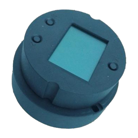
Microcyber MS0110 User manual

MS0110
HART Piezoresistance Silicon Pressure Module set
User Manual
Microcyber Corporation

Caution
1.Please don’t take off/install temperature board set at random.
2.Please check if the power of temperature board set meets the power request in the User Manual.
Version
V1.0
Disclaimer of Liability
We have reviewed the contents of this publication to ensure consistency with the hardware and
software described. Since variance cannot be precluded entirely, we cannot guarantee full
consistency. However, the information in this publication is reviewed regularly and any necessary
corrections are included in subsequent editions.
Microcyber Corporation 2015
The technical data may change at any time.

I
Table of Contents
Section 1 Overview.......................................................................................................................................... 1
Section 2 Instruction of piezoresistance Silicon pressure module set............................................................. 2
2.1 Dimension.......................................................................................................................................................... 2
2.2 Hardware interface........................................................................................................................................... 2
2.3 Failure warning and configuration protection dial switch............................................................................ 2
2.4 Bus Power Interface......................................................................................................................................... 3
2.5 Sensor Wiring.................................................................................................................................................... 3
2.6 System connection........................................................................................................................................... 4
Section 3 Working principle............................................................................................................................. 5
3.1 Working principle instruction........................................................................................................................... 5
Section 4 Pressure board set setting............................................................................................................... 7
4.1 Topology Connection....................................................................................................................................... 7
4.2 Function Configuration..................................................................................................................................... 8
4.2.1 Configuration Environment......................................................................................................................... 8
4.2.2 Basic Information Configuration................................................................................................................. 8
4.2.3 Configuration Information Setting.............................................................................................................. 9
4.2.4 Current Calibration..................................................................................................................................... 10
4.2.5 Variable Monitoring.................................................................................................................................... 12
4.2.6 Special Commands.................................................................................................................................... 13
Section 5 Adjustment in the Field.................................................................................................................. 14
5.1 LCD and Button Instruction........................................................................................................................... 14
5.2 General Adjustment Method......................................................................................................................... 14
5.3 List Function Items......................................................................................................................................... 15
5.4 Description for Special Symbols................................................................................................................... 17
Section 6 Maintenance .................................................................................................................................. 18
Section 7 Technical Specifications................................................................................................................ 19
7.1 Basic Parameters........................................................................................................................................... 19

II
Table of Figures
Figure 1 Pressure module set dimension.............................................................................................................. 2
Figure 2 Hardware interface instruction................................................................................................................. 2
Figure 3 Schematic diagram of silicon pressure module set.............................................................................. 3
Figure 4 Sensor power supply mode dial switch selection ................................................................................. 4
Figure 5 System connection schematic diagram.................................................................................................. 4
Figure 6 Product schematic diagram...................................................................................................................... 5
Figure 7 Silicon pressure sensor schematic diagram.......................................................................................... 5
Figure 8 (4~20) mA Compatible Mode................................................................................................................... 7
Figure 9 HART networking mode............................................................................................................................ 7
Figure 10 Basic Information..................................................................................................................................... 9
Figure 11 Configuration Information..................................................................................................................... 10
Figure 12 Current Calibration................................................................................................................................ 12
Figure 13 Variable Monitoring ............................................................................................................................... 12
Figure 14 Special commands................................................................................................................................ 13
Figure 15 Function Switch ..................................................................................................................................... 16

www.microcyber-fieldbus.com
1
Section 1 Overview
HART piezoresistance silicon pressure module set MS0110, using the fieldbus technology, is a new
generation of smart temperature module and it is an indispensable field device for process control. It
can be widely used in the petroleum, chemicals, electricity, and metallurgical industries, etc.
HART piezoresistance silicon pressure module set uses digital technology and it shall match multiple
thermal resistance and thermocouples sensors. It has wide range and simple interface between field
and control room, which reduces the expense of installation, operation and maintenance.

www.microcyber-fieldbus.com
2
Section 2 Instruction of piezoresistance Silicon
pressure module set
2.1 Dimension
35
3Φ
22
03
06
65
S Z
M
mm:tinU
Figure 1 Pressure module set dimension
2.2 Hardware interface
The whole hardware interface of HART piezoresistance silicon pressure module set is showed as
figure 2:
hctiwslaidedom erusserp/tnerruc tnatsnoC
eludom
noitaci nummoC
hctiws laidPWdnaLA
ecafretnirosnes erusserpnocilis3J
ecafretnirewop subTRAH5J
Figure 2 Hardware interface instruction
HART piezoresistance silicon pressure module set has four main interfaces:
Alarm setting(AL)and configuration protection setting(WP)hardware dial switch;
J5,HART bus power interface;
J3,silicon pressure sensor connection interface;
Constant current/pressure mode dial switch;
2.3 Failure warning and configuration protection dial switch
Dial switch with “AL” is for failure warning current setting and “WP” is for configuration protection
setting.

www.microcyber-fieldbus.com
3
Failure warning setting
HART piezoresistance silicon pressure module set has self-diagnosis function. Once the failure is
tested, such as sensor open circuit, sensor short circuit or AD failure, the board set shall output alarm
current automatically. The alarm current methods depend on the failure alarm current DIP switch
setting of the communication board. When AL DIP switch at OFF position is high alarm, the alarm
current is ≥21.75mA. When AL DIP switch at ON position is low alarm, the alarm current is ≤3.7mA.
Configuration Protection Setting
HART piezoresistance silicon pressure module set provides configuration protection DIP switch
setting. When it is (DIP switch at ON position) configuration protection, the board set is not allowed to
do any device configuration operation modification. When it is (DIP switch at OFF position)
configuration protection, the board set is allowed to do device configuration operation modification.
2.4 Bus Power Interface
MS0110 HART piezoresistance silicon pressure module set power and bus share the same a pair of
cable and it is called bus cable. The specific fieldbus cable recommended by IEC61158-2 is
suggested.
Bus cable should not share the same wiring pipe or wiring slot with other devices, and it shall be
away from high-power devices. The bus ends shall be grounded.
There is HART bus power interface for the communication board of HART piezoresistance silicon
pressure module set, and it can be used directly. And there is a terminal board to protect
communication board, shown as Figure 2, to protect bus power interface.
Please refer to Section 7.1 “Basic Parameter” for HART bus power voltage and requested matching
resistance in serial.
2.5 Sensor Wiring
htraE
edoidtnemerusaemerutarepmet lanretnirosnestcennoc
rosneS
tupnievitagenNI- tuptuoevitagenTUO-
tuptuoevitisopTUO+
tupnievitisopNI+
-T+T-V-A+A+V
3J
5J
+TRAH
-TRAH
Figure 3 Schematic diagram of silicon pressure module set

www.microcyber-fieldbus.com
4
HART silicon pressure module set supports constant voltage and constant current pressure sensor.
The connection for the two drive mode is as showed as figure 3. If pressure sensor internal doesn’t
have temperature measurement diode, silicon pressure module set will take A/D internal
temperature sensor for temperature compensation by default. Constant current and constant
pressure mode is controlled by dial switch. CC represents constant current and CV represents
constant pressure. Please refer to the figure below:
erusserp
tnatsnoC
6543
NO
21
VC
CC
VC
CC
VC
CC
6543
NO
21
VC
CC
VC
CC
VC
CC
tnerruc
tnatsnoC
Figure 4 Sensor power supply mode dial switch selection
2.6 System connection
noitarugifnoc TPMtraHnurCP ecnatsiserΩ052 teseludom erusserp nocilisTRAH
medomTRAH
CDV42rewoP
Figure 5 System connection schematic diagram

www.microcyber-fieldbus.com
5
Section 3 Working principle
The principle of pressure measurement for Silicon pressure module set is based on silicon pressure
sensor, using advanced microcontroller and sensor digitization measuring technique, high accuracy
algorithm to ensure pressure signal’s high precision measurement. The communication interface of
intelligent instrument uses advanced HART technology.
Silicon pressure module set is the same on logical construction, consisting of two parts, namely
communication module ( including acquisition circuit) and LCD module. Please refer to figure 6.
teseludoM
elbacsuB
eludom DCL
eludom noitacinummoC
rosneS
Figure 6 Product schematic diagram
3.1 Working principle instruction
Silicon pressure module set uses Piezoresistive silicon pressure sensor. When working, working
pressure make the isolation diaphragm skewed and transmit the pressure to resistance bridge
(semiconductor technology) via filling liquid. In this way, pressure-related bridge circuit output
pressure changes, which will be measured and further dealt.
Figure 7 Silicon pressure sensor schematic diagram
Communication module will not only be responsible for real-time collection pressure original AD
value, but also combination of AD vaule and calibration parameter for pressure value calculations,
which will pass on upper device via HART protocol. The communication module of HART silicon
pressure can also control D/A output by calculated pressure value, to realize the control of analog

www.microcyber-fieldbus.com
6
current signal. It also take charge of LCD module, intuitively show pressure module set’s current
state and tested pressure value.

www.microcyber-fieldbus.com
7
Section 4 Pressure board set setting
4.1 Topology Connection
The connection modes of smart transmitter with HART piezoresistance silicon pressure module set
can be divided into 4~20mA compatible mode and networking mode.
4~20mA Compatible Mode(refer to figure 8)
Figure 8 (4~20) mA Compatible Mode
Feature:
1)Connect to upper control system via AI module and HART communication device;
2)Use digital and analog communication;
3)Device address is 0.
Networking Mode (Refer to figure 9)
Figure 9 HART networking mode
Feature:
1)Connect to upper control system via HART communication device;
2)Use digital function only and the current is fixed 4mA;

www.microcyber-fieldbus.com
8
3)Under short address format, it supports at ost 15 equipment networking.
4.2 Function Configuration
HART piezoresistance silicon pressure module set supports Microcyber’s HartMPT Configuration
Software for configuration debugging. Following is an example for HartMPT Configuration Software,
including functions below:
1)Basic information configuration: configure the basic information of device online, including tag,
address, date, assemble number and so on;
2)Configuration information configuration: configure the configuration information of device online,
including PV range, damp and so on;
3)Current calibration: Can calibrate 4~20mA current of online device, also can set fixed current
output;
4)Variable monitoring: refresh all dynamic variable of selected online device timely and display trend
curve of present device primary value.
4.2.1 Configuration Environment
1)PC with serial port, Windows 2000/Windows XP;
2)HART Modem and serial wire;
3)Matching resistance 230Ω~550Ω.
4.2.2 Basic Information Configuration
Through basic information dialog, the basic information of the smart transmitter can be read or
modified, including device address, information, description, date, assembly number, alarm, write
protection, manufacturer ID, manufacture, device type, device ID, long address and version info,
shown as Figure 10.

www.microcyber-fieldbus.com
9
Figure 10 Basic Information
After information modification, click the “Apply” button to download it into device.
1)The address selection range is 0~15;
2)Information can be input 32 characters at most;
3)The maximum length of the description is 16 defined characters;
4)The maximum length of the tag is 8 defined characters;
5)Date range is from the year 1900 to 2155.
6)Assembly number is 6 defined characters at most.
4.2.3 Configuration Information Setting
Through configuration information dialog, the configuration information of smart transmitter can be
read or modified, including displayed device output variable (primary variable, cold end temperature
value, current value and percentage), primary variable info setting (damp value, unit, upper limit and
lower limit) and range calibration, etc., shown as Figure 11.

www.microcyber-fieldbus.com
10
Figure 11 Configuration Information
Damp: range 0~32s
Unit: PV unit modification affects variables related to unit,
such as the upper or lower limit for the range or for the sensor. When you modify the unit, you can’t
modify upper or lower limit for the primary variable range, instead, you should modify them
separately.
The unit can be set as:inH2O, inHg, ftH2O, mmH2O, mmHg, psi, bar, mbar, g/cm2, kg/cm2, Pa,
kPa, MPa, torr, atm, inH2O@4degC, mmH2O@4degC。
Upper limit of the range: Corresponding to PV value of 20mA output current.
Lower limit of the range: Corresponding to PV value of 4mA output current.
You should press “Apply” to download it into device after the modification.
Set “upper limit of range” with present value: Set the PV as the upper limit of primary variable
range, and keep the lower limit of range the same as previously.
Set “lower limit of range” with present value: Set the PV as the lower limit of primary variable range,
it may probably modify upper limit at the same time.
Set “primary variable zero point” with present value: Set the PV as the primary variable zero point
when the pressure is 0.
4.2.4 Current Calibration
The steps of current calibration are shown as following:
1)Connect the loop, an ammeter with the 5 1/2 digit precision should be series-wounded in the
device output loop.

www.microcyber-fieldbus.com
11
2)Set device rolling address as 0, please refer to basic info configuration. If rolling address is 0
already, this step can be skipped.
3)Enter current calibration option TAB.
4)Select “current value” as 4mA, when the ammeter is stable, input the value in ammeter to
“adjustment value”, and then click “Apply”.
5)Select “current value” as 20mA, when the ammeter is stable, input the value in ammeter to
“adjustment value”, and then click “Apply”.
6)Select “current value” as blank, makes the device output current as PV value.
Notes: When the present output current value is high alarm current, the user cannot calibrate 4mA.
When the present output current value is low alarm current, the user cannot calibrate 20mA.
Configure Current Fixed Output
The user may set fixed current output in current calibration tab. Input the value of the current the
smart transmitter will be fixed on, to “fixed current value”, and click the button “enter/exit fixed current
mode” to enter or exit the mode of fixed current output. The text of the button can display “exit fixed
current mode” and “enter fixed current mode” in turn, to tell users what to do.
In the run of the HART smart transmitter, compare the value of the primary variable and range
upper/lower limit of the primary variable continuously. When the value of the primary variable
exceeds the range of the primary variable, the smart transmitter will output fixed current to indicate
that the value of the primary variable is exceeded. When it is over the upper limit, the smart
transmitter output fixed current 20.8mA;When it is less than the lower limit, output is 3.8mA.

www.microcyber-fieldbus.com
12
Figure 12 Current Calibration
Note: Calibration current and fixed current output functions are only in the moment when the polling
address is 0. It will be at absolute digital communication mode at other polling addresses, the failure
info is “Command Execution Failure”.
4.2.5 Variable Monitoring
The user is able to refresh all the dynamic variables of the selected device and display trend curve of
present device primary variable via variable monitoring tab. The present refreshing variables are: PV
value, current value, percentage and SV value.
Figure 13 Variable Monitoring

www.microcyber-fieldbus.com
13
4.2.6 Special Commands
The user is able to configure LCD type, small signal cut parameter, and is able to operate data
restore and save via special command optional tab. Shown in Figure 14:
Figure 14 Special commands

www.microcyber-fieldbus.com
14
Section 5 Adjustment in the Field
5.1 LCD and Button Instruction
HART piezoresistance silicon pressure module set has lattice LCD and local button adjustment
function, and the user can do parameter adjustment in local for HART piezoresistance silicon
pressure module set.
There are 3 buttons, 【M】,【S】and【Z】. 【M】is mode button, in charge of “function option”, “cursor
move” and “confirm”. 【S】and 【Z】are input adjustment buttons, in charge of “list front/back turn”
and “data add and subtract”.
5.2 General Adjustment Method
List scan
In measurement display mode, press 【M】for lone, to enter function list tab, and then press 【S】
or【Z】to scan the whole function list tab.
Password input
Press 【S】or【Z】to adjust list as “Fun 01”, and the list is password function, so the user shall only
operate other function if the input password is right. And then the user shall press 【M】to enter
password input status, and the password is “00005”. Press 【S】or【Z】to adjust the value, and then
press 【M】to adjust cursor position, after that, press 【M】to confirm, and then the system shall be
return automatically to list scan mode.
Function setting
In list scan mode, press 【S】or【Z】to choose function to adjust, and press 【M】to enter function
adjustment, after that, press 【M】to confirm and return to list scan mode, and then go on to adjust
following functions.
Data save
After finishing the function setting, in list scan mode, press 【S】or【Z】to adjust list as “Fun 99”, and
this list is data save confirm function. Press 【M】to enter, 【S】or【Z】to choose “SAVE”, and then
press 【M】to confirm to save.
Now the local adjustment functions are finished, the user shall adjust many function items once, and
then adjust to “Fun 99” to save all the data once.

www.microcyber-fieldbus.com
15
5.3 List Function Items
Here is the introduction for HART piezoresistance silicon pressure module set’s local button
operations. With field adjustment, the user shall adjust PV unit, PV upper limit, PV lower limit, LCD
display type etc. The supported functions are shown as following
No.
Parameter
Remarks
01
PASSWORD
Local adjustment, input password: 00005
Save as factory value, input password: 62259
Recover as factory value, input password: 25917
It shall execute as soon as input password for “Save as factory value” and
“Recover as factory”.
03
LOWER
Set current value as PV range lower limit. System will auto-save it after
setting, not necessary to switch to “Fun 99” for manual saving.
04
UPPER
Set current value as PV range upper limit. System will auto-save it after
setting, not necessary to switch to “Fun 99” for manual saving.
05
DAMP
0~32 Set damping time 0~32s
06
LRV
Passive setting for PV lower limit
07
URV
Passive setting for PV upper limit
08
ZERO
User present value to set PV zero point
10
FUNCT
Choose PV output function
11
DISPLAY
Set LCD display content
12
UNIT
Set PV unit
99
SAVE
After the above functions, the user shall execute SAVE function to finish
local adjustment.
Note:
The user shall execute “Fun 99” data save function. All the function adjustments shall be finished.

www.microcyber-fieldbus.com
16
Figure 15 Function Switch
Table of contents
Other Microcyber Measuring Instrument manuals
Popular Measuring Instrument manuals by other brands
BRUEL & KJAER
BRUEL & KJAER 2225 instruction manual
Sierra
Sierra 760S Series instruction manual

Fluke
Fluke T5-600 Service information
EUTECH INSTRUMENTS
EUTECH INSTRUMENTS CYBERSCAN PC 5000 PHCONDUCTIVITY METER instruction manual
Major tech
Major tech MT95 instruction manual
Myron L
Myron L 512T2 Operation instructions
