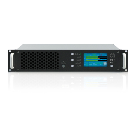
Microcyber CS-TT106H-V2.0 User manual

NCS-TT106H-V2.0 Intelligent
HART Temperature Transmitter
User Manual

http://www.microcyber-fieldbus.com
Warning
1. It is forbidden for users to disassemble the temperature
module by themselves.
2. Please check if the supply voltage of temperature transmitter
meets the power supply voltage requirements in the manual.

http://www.microcyber-fieldbus.com
Company Introduction
Microcyber Corporation,established as a high-tech enterprise
by the Shenyang Institute of Automation Chinese Academy of
Sciences, mainly engages in advanced industrial control systems,
equipments, instruments and chips for industrial process automation
control solutions in the research, development, production and
application. Microcyber undertakes a number of national scientific
and technical key task and “863” project, and has Liaoning
Province networked control systems engineering research
center. The company successfully developed the FF H1 fieldbus
protocol stack which is number one to be approved
internationally in China, and the Industrial Ethernet
Protocol(HSE) which is number one to be approved in China, and the
domestic first fieldbus instrument which has a function of
national-level intrinsically safe explosion--proof and safety barrier.
Also Microcyber participated in the drafting of the domestic first
Ethernet-based industrial automation protocol standards (Ethernet
for Plant Automation, EPA). As a result, serial products are
composed of configuration, control software, embedded software,
control system, instrument chip to the
OEM board, and make Microcyber be an industrial automation
products provider in full range, and also further Microcyber‟s
leading position in the field of fieldbus technology.
Microcyber is the FF member, the HART member and the
Profibus National Organization (PNO) member.

http://www.microcyber-fieldbus.com
Microcyber passes the Authentication of ISO 9001 Quality
System, and has an outstanding innovative R&D team, plentiful
practical experiences of design of the Automatic engineering, a
leading product series, a huge market network, a strict quality
management system and an excellent enterprise culture. All these
further a solid foundation of entrepreneurship and sustainable
development for Microcyber.
Carrying the ideals of employees, creating customer value and
promoting enterprise development.
Microcyber is making progress with China.

http://www.microcyber-fieldbus.com
Catalogue
1. BRIEF INTRODUCTION.........................................................................................1
2. INSTALLATION......................................................................................................2
2.1 DIMENSION......................................................................................................2
2.2 INSTALLATION................................................................................................... 3
2.3 WIRING...........................................................................................................3
3. HART TEMPERATURE TRANSMIITER CONFIGURATION....................................... 5
3.1TOPOLOGY CONNECTION..................................................................................... 5
3.2 FUNCTIONAL CONFIGURATION............................................................................. 6
4 MAINTENANCE................................................................................................... 18
5 TECHNICAL SPECIFICATION.................................................................................20
1.1 BASIC PARAMETER...........................................................................................20
1.2 RTD PARAMETER............................................................................................ 21
1.3 THERMOCOUPLE............................................................................................. 21
1.4 PHYSICAL PARAMETER...................................................................................... 22

Temperature Transmitter | NCS TT106 | Page
Email | fang.siqi@microcyber.cn
http://www.microcyber-fieldbus.com
1
NCS-TT106H-V2.0 fieldbus temperature transmitter, using the
fieldbus technology, is a new generation of smart fieldbus
temperature transmitter and it is an indispensable field device for
process control. NCS-TT106H-V2.0 integrates abundant function
blocks and realizes not only general measurement function but also
complicated control strategy.
NCS-TT106H-V2.0 uses digital technology, so it can connect with
many types of thermocouple and thermo resistive sensors. It has
wide range and simple interface between field and control room,
which reduces the expense of installation, operation and
maintenance.
NCS-TT106H-V2.0 fieldbus temperature transmitter supports
HART, FF, and PA protocols. It can be widely used in the petroleum,
chemicals, electricity, and metallurgical industries, etc.
1. BRIEF INTRODUCTION

Temperature Transmitter | NCS TT106 | Page
Email | fang.siqi@microcyber.cn
http://www.microcyber-fieldbus.com
2
2.1 Dimension
Figure 2.1 Dimension of Temperature Transmitter (Unit: mm)
2. INSTALLATION

Temperature Transmitter | NCS TT106 | Page
Email | fang.siqi@microcyber.cn
http://www.microcyber-fieldbus.com
3
2.2 Installation
Via positioning hole, use two screws to install the temperature
module to temperature housing or rail.
Figure 2.2 Installation
2.3 Wiring
Figure 2.3 Wiring
Fieldbus temperature transmitter power and bus signal share a
pair of cable, and it is called bus cable. It is suggested the user use

Temperature Transmitter | NCS TT106 | Page
Email | fang.siqi@microcyber.cn
http://www.microcyber-fieldbus.com
4
fieldbus special cable recommended by IEC61158-2.
The signal cable and bus cable cannot share wires or wire slot
with other device power wire, and they shall be away from device
with high power.
The shielded wires of bus ends shall be connected to the
ground.

Temperature Transmitter | NCS TT106 | Page
Email | fang.siqi@microcyber.cn
http://www.microcyber-fieldbus.com
5
3.1Topology Connection
The connection mode of HART smart transmitter can be divided
into 4~20mA compatible mode and networking mode.
4~20mA compatibility mode (as shown in Figure 3.1)
第一主设备:
控制系统或其他主
机应用程序
模拟仪表
手持器 TT106 HART模块
HART接口
设备
电源
数字通讯(每秒更
新2~3次)
Figure 3.14~20mA compatible mode
Features:
1) Access to the upper level control system through the AI
module and HART communication device;
2) Mixed use of analog and digital communication methods;
3) The device address is 0.
3. HART TEMPERATURE TRANSMIITER
CONFIGURATION

Temperature Transmitter | NCS TT106 | Page
Email | fang.siqi@microcyber.cn
http://www.microcyber-fieldbus.com
6
Networking mode (as shown in Figure 3.2)
手持器
控制系统或其它主站
输入/输出系统
H A R T T T 1 0 6 H A R T T T 1 0 6 H A R T T T 1 0 6
Figure 3.2 HART Networking mode
Features:
1) Access to the upper level control system through the HART
communication device;
2) Using only the digital function of the HART system, the
current on the line is fixed at 4 mA;
3) Supports up to 64 device networking in short address format.
3.2 Functional configuration
The intelligent temperature transmitter supports Microcyber
Corporation's HartMPT configuration software, HART FCG's SDC625
and other general HART configuration software for configuration
debugging. The following is an example of Microcyber's HartMPT
configuration software to introduce the configuration method of the
intelligent temperature transmitter. It mainly includes the following
functions:
1) Basic information configuration: configure the basic
information of the online device, including the label, address, date,

Temperature Transmitter | NCS TT106 | Page
Email | fang.siqi@microcyber.cn
http://www.microcyber-fieldbus.com
7
assembly number and other information;
2) Configuration information configuration: configure the
configuration information of the online device, including the main
variable range, damping and other information;
3) Sensor information configuration: configure sensor
information of the online device, including type, line system and
other information;
4) Current calibration: It can calibrate the 4~20mA current of
the online device, and can also set the fixed current output;
5) Variable monitoring: It can periodically refresh all dynamic
variables of the selected online device and display the trend curve of
the current device host variable.
Configuration environment
1) PC with serial port, operating system is Windows
2000\Windows XP;
2) HART Modem and serial cable;
3) Matching resistance is 250Ω~550Ω.
Basic information configuration
The basic information tab allows you to read or modify the basic
information of the smart transmitter, including device address,
message, description, label, date, assembly number, alarm, write
protection, manufacturer ID, manufacturer, device type, device ID. ,
long address and version information, as shown in Figure 3.3.

Temperature Transmitter | NCS TT106 | Page
Email | fang.siqi@microcyber.cn
http://www.microcyber-fieldbus.com
8
Figure 3.3 Basic Information
After the information is modified, you can download it to the
device by pressing the “Apply” button.
1) The selection range of the address is 0 to 63;
2) The message can be entered up to 32 characters;
3) Description can input up to 16 specified characters;
4) The maximum length of the label is 8 specified characters;
5) The date range is from 1900 to 2155;
6) The maximum length of the assembly number is 6 specified
characters.
Configuration information configuration

Temperature Transmitter | NCS TT106 | Page
Email | fang.siqi@microcyber.cn
http://www.microcyber-fieldbus.com
9
The smart transmitter configuration information can be read or
modified via the configuration information tab.
Including display device output variables (main variable, cold
junction temperature value, current value, percentage), setting of
main variable information (damping value, unit, range upper limit,
range lower limit), calibration of range and alarm current Settings,
etc., as shown in Figure 3.4。
Figure 3.4 Configuration information
Damping: Range 0 to 32 seconds.
Unit: The change of PV unit directly affects the variables
associated with the unit, such as the upper and lower

Temperature Transmitter | NCS TT106 | Page
Email | fang.siqi@microcyber.cn
http://www.microcyber-fieldbus.com
10
limits of the range, the upper and lower limits of the
sensor, and so on. When modifying the unit, you cannot
modify the upper and lower limits of the main variable
range at the same time, and should be modified
separately.
The unit can be set to: ゚C, ゚F, ゚R, K, mV, Ohm.
Upper range: PV value corresponding to 20mA output
current.
Lower range: PV value corresponding to 4mA output current.
Alarm type: high alarm and low alarm.
Alarm value: When the alarm type is high alarm, it can be
21.75mA to 23.00mA
The alarm current is set within the range; when the alarm type
is low alarm, the alarm current can be set within the range of
3.50mA to 3.75mA.
After the information is modified, you can download it to the
device by pressing the “Apply” button.
Set the “Range Upper Limit” button with the current value:
set the current PV value of the device to the upper limit of
the main variable range, and the lower limit of the range.
Set the “Lower Limit” button with the current value: Set the
current PV value of the device to the lower limit of the
main variable range, which may change the upper limit at
the same time.
Set the “Main Variable Zero” button with the current value:
Use the current PV value of the device as the main variable

Temperature Transmitter | NCS TT106 | Page
Email | fang.siqi@microcyber.cn
http://www.microcyber-fieldbus.com
11
zero.
Sensor configuration
The sensor information tab allows you to view the currently
configured sensor information (upper, lower, and minimum spans)
and to configure each sensor type, line, and other information. As
shown in Figure 3.5.
Figure 3.5 Sensor configuration
Sensor type:supported sensor models are as below:
Sensor type
Description
0_500R
Resistance,0 ~ 500Ω
0_4000R
Resistance,0 ~ 4000Ω

Temperature Transmitter | NCS TT106 | Page
Email | fang.siqi@microcyber.cn
http://www.microcyber-fieldbus.com
12
CU50
Cu50
CU100
Cu100
PT100
PT100
PT1000
PT1000
100MV
mV voltage signal, range:-100 ~ 100 mV
B_TC
B thermocouple
E_TC
E thermocouple
J_TC
J thermocouple
K_TC
K thermocouple
N_TC
N thermocouple
R_TC
R thermocouple
S_TC
S thermocouple
T_TC
T thermocouple
Wiring system:It can be set to 2-wire system, 3-wire system
and 4-wire system, only effective for RTD.
Cold-end temperature compensation: it can be set to prohibit,
internal measurement and external measurement. When
the cold-end temperature compensation is prohibited, the
transmitter will not carry out the cold-end temperature
compensation; when the cold-end temperature
compensation is enabled to measure internally, the value
of the cold-end temperature compensation is measured by
the internal temperature measuring chip; when the
cold-end temperature compensation is enabled to measure
externally, the external two-wire system Pt100 is used, and

Temperature Transmitter | NCS TT106 | Page
Email | fang.siqi@microcyber.cn
http://www.microcyber-fieldbus.com
13
then the value of the cold-end temperature compensation
is measured by the external Pt100.
Channel status: Display sensor channel status (open circuit,
short circuit & etc.).
Sensor channel value: Display the original value of sensor
channel.
Cold end temperature: Display the current cold end
temperature.
R0 Correction Factor: Correction of the error of the sensor
itself (range 0.9-1.1).
Two-wire zero calibration: When the temperature
transmitter is connected to RTD in 2-wire mode,to avoid
the error caused by the resistance on the cable, the sensor
end can be short connected, and then the zero calibration
button can be executed to eliminate the error caused by
the resistance on the cable.
TC Calibration: Calibration of various thermocouple ranges of
transmitters is carried out in the factory (only applicable to
manufacturer-level users).
RTD calibration: All kinds of resistance ranges of transmitter
are calibrated out of the factory (only for
manufacturer-level users).。
Restore factory default value: Click this button, all data will
be restored to the default factory status.
Save as factory value: Click this button to save the current
configuration as factory value. When you click the “Restore

Temperature Transmitter | NCS TT106 | Page
Email | fang.siqi@microcyber.cn
http://www.microcyber-fieldbus.com
14
factory settings” button again, the saved configuration will
be restored.
Restore factory settings: Click this button to restore data to
factory status. If the user has saved the factory value, the
configuration saved by the user will be restored; otherwise,
the default factory status will be restored.
Current Calibration
The current calibration steps are as follow:
1) To connect the circuit, more than five and a half bits
ammeter should be connected in series in the output circuit of the
equipment.
2) Set the polling address of the device to be 0. Refer to the
basic information configuration. If the polling address is 0, you can
skip this step.
3) Enter the current calibration tab;
4) Select the current value as 4mA. After the ammeter is
stable, input the ammeter reading in the text box of “Adjustment
Value” and click the “Application” button.
5) Select the “current value” of 20 mA. After the ammeter is
stabilized, enter the ammeter reading in the “adjustment value” text
box and click the “application” button.
6) Select "current value" as blank, so that the output current
of the equipment is calculated according to PV value.
Configuration current fixed output:
Users can configure a fixed current output in the current

Temperature Transmitter | NCS TT106 | Page
Email | fang.siqi@microcyber.cn
http://www.microcyber-fieldbus.com
15
calibration tab, click the given fixed current value or “Manual Send”
and fill in the fixed current value to be output, click “Enter/Exit Fixed
Current Mode” to enter or exit the fixed current output mode. The
title of the button alternately displays “Enter Fixed Current Mode”
and “Exit Fixed Current Mode” to prompt the user to operate.
HART intelligent transmitter continuously compares main
variable value with the upper and lower limit value. When main
variable value exceeds the upper and lower limit, the module
outputs fixed current, indicating that the main variable exceeds the
range. When the main variable is higher than the upper limit, the
output is fixed at 20.8 mA. When it’s lower than the lower limit, the
output is fixed at 3.8 mA.
Table of contents
Other Microcyber Transmitter manuals
