5. Active channels setting
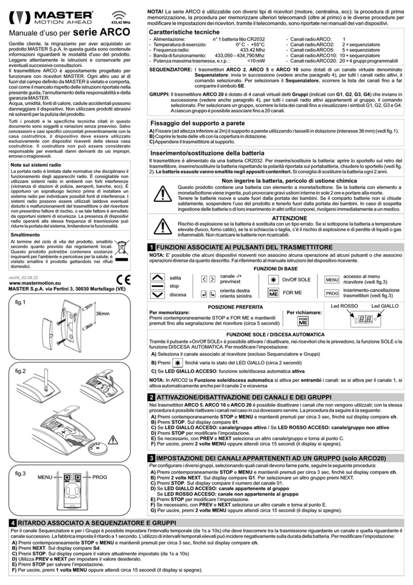
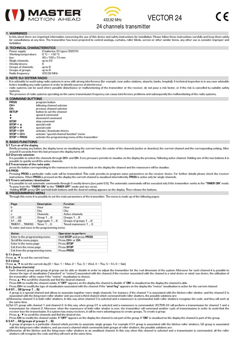
If the transmitter radio channel numbers are above the needful, is possible deactivate the radio channel in excess. Anyway it will be possible in every moment active again this radio
channel.
To ena le or disa le the radio channels:
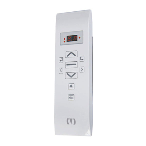
-Keep press PREV and also press NEXT and keep hold both buttons for about 10 sec, until on the display llightning the symbol 01.
-Using PREV or NEXT to select the channel to be enable or disable.
-If on the right of the channel number the point is turn on, it indicates that the channel is actually enable.
-To change the setting press STOP.
-Repeate for all channels to change the settings.
-Completed all settings waiting that the display switches off (about 10 sec) or press shortly PROG.
-If the operation is correctly performed, using PREV and NEXT will scroll on the display only the keep activate channel.
6. Virtual Channels
6.1 Sequence program (VECTOR 5 – VECTOR 10)
The VECTOR 5 and VECTOR 10 transmitters have both a virtual channel (sequence program). The sequence program is indicate on the display with symbol “SE”. If is select the sequence
program channel and order a supported command (up, stop, down, stop+up, stop+down), this command will be send to all active radio channels.
6.2 Groups (VECTOR 20)
The VECTOR 0 transmitter has 4 programmable virtual channel (groups). Groups will be indicated on display with symbols “G1” … “G4”. If a group is select and order a supported
command (up, stop, down, stop+up, stop+down), this command will be send in series to all active radio channels member of the group.
6.2.1 Setting of groups
-Keep hold down STOP hold also PROG and keep hold both buttons for about sec, until on the display shows the symbol G1.
-Using PREV or NEXT to select the group to set up.
-Press STOP. On display lighting the symbol 01.
-If on the right of channel number the point is turn on, it indicates that the channel belongs to the group.
-To change setting press STOP.
-Using PREV or NEXT to scroll the channel and STOP to change setting.
-Completed all settings waiting (about 10 sec) or press shortly PROG. The display stops to lighting and appares the group symbol just setting.
-Repeate for all groups to change setting.
-Completed all group setting waiting that display switching off (about 10 sec), or press shortly PROG.
Note:
If a group is active but anyone belong to the group, the command of this group cannot be follow and the display visualize symbol Er (Error).
7. “Sun” Function / ”Automatic Downward” Function
If the receiver device has “Sun” function or “Automatic Downward” function, is possible activate or deactivate the function directly form the transmitter. The factory sets up this function as
“inactive”. If the point on the right of the channel number is turn on, it indicates that for that channel “sun”/”automatic downward” function is active.
To change this setting:
-Usinig PREV or NEXT to select the channel.
-Keep hold STOP, hold also NEXT and keep hold both for about sec, until the point on the right of the channel number change condition (if switching off it switches on, if switching on
it switches off).
-Execute a transmission to communicate the change to receiver control tuned to the channel.
8. “Anemometric Test”function / ”Delay with insertion on general command” Function
If the receiver device has “Anemometric Test” function or “Delay with insertion on general command” function, is possible activate or deactivate this function directly from the transmitter.
The factory sets up this function as “inactive”. If the point between the two codes of the channel number is turn on, it indicates that for that channel “Anemometric Test ”/” Delay with
insertion on general command” function is active.
To change this setting:
-Using PREV or NEXT to select the channel.
-Keep hold STOP hold also PREV and keep hold both for about sec, until the point between the two codes of the channel number change condition (if switching off it switches on, if
switching on it switches off ).
-Execute a transmission to communicate the change to receiver control tuned to the channel.
9. Indication attery loading condition
To verify the battery loading condition, keep hold PREV hold also NEXT. The display indicates H (battery high) if the battery is load, L (battery low) if the load battery level is not enough
to assure full capacity of the transmitter (the transmission capacity will be reduced gradually until to be necessary battery replacement).
10. Battery Replacement
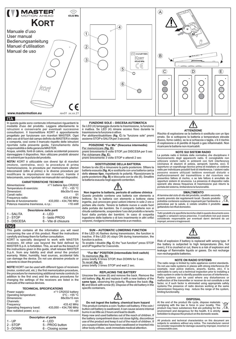
This transmitter is powered by 3 Volts Battery type CR 03 . To replace the batteries, open the unscrew, the back of the transmitter and slip off the expired battery, replacing with a new
ones, pay attention with the polarity. Reintegrate the unscrew in its special side.
WARNING: explosion danger if the attery is replaced with an unsuitta le one. The expired attery must e disposed in the special containers
11. Expired
At the end of the cycle of the product, dispose as provided by local regulation. This product can be contain polluting substance for the environment and dangerous for
health, is forbidden dispose the product with the domestic waste.
-All the products and the specific techicals contained in this document are subjected to variations without any warning.
-Only in case of concessions and specific case preaviusly agreement with the head office the device has to be used only with received device from the same head office.
-The manufacturer can not be considerated responsable for eventual damage caused by inappropriate, wrong or unreasonable use.
-MASTE declares that the device is accordance with the principal requirement and the other arrangement provided by directive 1999/5/CE. The declaration of conformity is available in this site http://www.mastermotion.eu.it-
IT/download.


