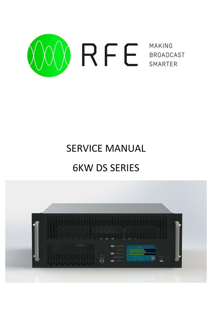
RFE DS Series User manual

1
USER MANUAL - TRANSMITTER DS SERIES - 30 - 50 - 100 - 500 - 1000W
Rev 1.3
USER MANUAL
TRANSMITTERS DS SERIES
30|50|100|300|500|1000W

Rev 1.3
USER MANUAL - TRANSMITTER DS SERIES - 30 - 50 - 100 - 300 - 500 - 1000W
2
Index
Indice ................................................................................................... 2
Introduction & general information structure ...................................................... 4
Hazardous Voltage Warning ............................................................................. 4
General Safety Recommendations .................................................................... 5
Document structure ........................................................................................ 6
Scope of the document ................................................................................... 6
Introduction ................................................................................................... 7
Features ........................................................................................................ 10
Diagram block ................................................................................................ 11
Technical Specifications .................................................................................. 12
Installation and Use ........................................................................................ 13
Front panel .................................................................................................... 13
Rear panel ..................................................................................................... 14
Operating instructions ..................................................................................... 15
RF On/Off Switching .................................................................................... 16
Fault/Reset Key ........................................................................................... 17
Installation .................................................................................................... 18
Unpacking .................................................................................................. 18
First power-on and setup .............................................................................. 18
Quick start .................................................................................................... 19
Menu .............................................................................................................. 20
Menu - Frequency ........................................................................................ 21
Menu - Power .............................................................................................. 22
Menu - Audio Settings .................................................................................. 22
Menu - Settings ........................................................................................... 25
Lan configuration ...................................................................................... 26
Date/Time Settings .................................................................................... 28
DB25 Settings .......................................................................................... 29
Address port RS485 .................................................................................. 30
19kHz Output Amplitude/Dev Amplitude/Dev Ph ........................................... 30
Power Reduction Settings ............................................................................. 31
Set FSK/ID-Code Settings .............................................................................. 32
AES/EBU Settings ........................................................................................ 32
Audio C.O./Reserve audio source ................................................................... 33
Options Status ............................................................................................. 33
Preset - Settings ............................................................................................ 34
Alarms/Log Event ........................................................................................... 36

3
USER MANUAL - TRANSMITTER DS SERIES - 30 - 50 - 100 - 500 - 1000W
Rev 1.3
DB25 and DB9 pinout ..................................................................................... Appendix A
Touch screen calibration ................................................................................. Appendix B
Upgrade Firmware .......................................................................................... Appendix C
Log-event and Alarms list ................................................................................ Appendix D
Web Page Control-SNMP ................................................................................. Appendix E
Support system .............................................................................................. Appendix F

Rev 1.3
USER MANUAL - TRANSMITTER DS SERIES - 30 - 50 - 100 - 300 - 500 - 1000W
4
Introduction & general information structure
This manual contains all informa on for installa on and maintenance of DS
transmi ers and is divided into two parts: the fi rst concerning operator that has to
use equipment, the other concerning maintenance technicians. The two sec ons are
separated by one blue page to quickly iden fy them.
The operator who normally has experience in using the equipment should not try
to perform any ac on which has been classifi ed as belonging to the maintenance
technician. Any incorrect opera on may cause damage to equipment electronics
and can be also poten ally dangerous for operator’s safety.
The RF power amplifi er has been designed for con nuous wave (CW) modes.
Technological cu ng-edge solu ons and latest genera on materials (such as sixth
genera on LDMOS) ensure a high standard of quality and robustness.
Hazardous Voltage Warning
WARNING:
Voltage within equipment is high enough to endanger life!
Do not remove external and internal covers!
this opera on is to be done by qualifi ed and authorized
personnel only!
HAZARDOUS
VOLTAGE

5
USER MANUAL - TRANSMITTER DS SERIES - 30 - 50 - 100 - 500 - 1000W
Rev 1.3
General Safety Recommendations
All work on transmi er system as well as installed units, e-g- the VHF/FM transmi er,
may only be carried out by trained personnel capable of iden fying dangerous
situa ons or condi ons. Take note of the following:
• Before working on a transmi er system, that is even before removing the VHF/
FM transmi er ensure that the correponding system documenta on is consulted.
• Before workign on an open unit ensure that the fuse ahead of the unit is
disengaged or the power cable to the unit is disconnected.
• Note that when service work is carried out, e.g. measurements or se ngs are
made during transmi er opera on, voltage carrying parts are not always secured
against touching.
• All work is to be carried out with great cau on.
CAUTION!
The VHF/FM transmi er does not possed a mains switch. Even when the transmi er
system is in the “OFF” state, voltages are s ll present at the assemblies of the VHF/FM
transmi er, e.g. mains power at the input of the power supply module is live and the
fan is in opera on.
Assemblies with components incorpora ng toxic substances are labelled as follows:
A warning sign as shown in the adjacent fi gure is glued to a component incorpora ng
a Toxic substance of glued in the vicinity of the component.
Warnung
Dieses Bauelement enthält Beryllium-Oxid, das in fein verteilter
Form giftig ist. Bei bestimmungsgerechter Verwendung des
Bauelementes entstehen keine Gefahren.
Gegebenenfalls sind entsprechende Sicherheits- und Umwelt-
vorschriften zu beachten.
Identifi cation of Toxic Substances
B e r y l l i u m o x i d

Rev 1.3
USER MANUAL - TRANSMITTER DS SERIES - 30 - 50 - 100 - 300 - 500 - 1000W
6
Warning notices in this Manual
This label is used in the manual to indicated where incorrect
or non-compliance with direc ons or with procedures
relevant to electrical safety could easily lead to injury or fatal
Transmi er systems and equipment of RFE Broadcast S.r.l. are built exclusively
for use as in the terms of contract. Any other use is not in accordance with the
manufacturers s pultaions. The manufacturer is not liable for damage resul ng from
such use; the risk is carried alone by the customer.
Use according to s pula on includes opera ng, maintenance and servicing
procedures as directed by manufacturer. The transmi er system of RFE Broadcast
S.r.l. may only be operated, maintened and serviced by qualifi ed technical personnel
familiar with the relevant safety precau ons.
RFE Broadcast S.r.l. shall not be liable for any damages caused by unauthorised
modifi ca ons carried out by the customer on the transmi er systems or equipment
of RFE Broadcast S.r.l. or unauthorised modifi ca ons at interfaces to the equipment
of RFE Broadcast S.r.l.
Original parts and accessories are specially design for our products. Parts and
accessories not delivered by us have not been tested nor approved for use in our
equipment. Fi ng and/or use of suck items may alter the given characteris cs of
out products in an adverse manner such that ac ve and/or passive safety may be
impaired. We assume no obliga on or liability for damages cause by parts and
accessories not delivered by us.
A en on must be paid to important no ces contained in this manual. They are
labelled as follows:
W
A
R
N
I
N
G
!
This label is used in the manual to indicated where incorrect
or non-compliance with direc ons or with procedures
relevant to electrical safety could easily lead to damage to
C
A
U
T
I
O
N
!
Use according to stipulation

7
USER MANUAL - TRANSMITTER DS SERIES - 30 - 50 - 100 - 500 - 1000W
Rev 1.3
First aid

Rev 1.3
USER MANUAL - TRANSMITTER DS SERIES - 30 - 50 - 100 - 300 - 500 - 1000W
8
Document structure
This document contains all the technical informa on rela ng to the transmi ers of
Series DS.
In the fi rst part we have all the technical specifi ca ons, followed by direc ons for
the fi rst installa on of the transmi er.
In the middle there is the explana on of the menu and func ons of the transmi er,
such as color display touch screen.
There are explanatory photos of the various components of the transmi er.
Finally, follow the wiring diagrams and layouts.
Scope of the document
Purpose of this document is to provide a comprehensive descrip on of the
func onali es of the DS TRANSMITTER and to provide opera ng informa on on the
so ware elements of the system.
DS TRANSMITTER User Manual provides so ware setup informa on.

9
USER MANUAL - TRANSMITTER DS SERIES - 30 - 50 - 100 - 500 - 1000W
Rev 1.3
Introduction
The transmi er DS is designed with all the latest technologies, such as high effi ciency
using the latest genera on LDMOS transistor and high effi ciency power supplies. We
used a modern interface and performance using a color display with touch screen,
with easy management so ware and easy to use. Each transmi er DS is equipped
with a LAN interface with the possibility of remote control completely the transmi er
opera on.
The transmi er DS is equipped with all audio inputs including Audio IP (as op on),
Fig. 1: Front View of the VHF/FM Transmi er DS30-50-100-300-500-1000
The VHF/FM transmi er DS30-50-100-300-500-1000 is intended for the transmission
of frequency modulated broadcasts in mono or stereo. It works with broadband
characteris cs in the VHF frequency range from 87.5~108 MHz and can be operated
with any frequency in this range without alignment.
The transmi er output power is variable between 10 W and 30 W. The transmi er is
available with diff erent remote control ports. It can store up to six broadcast programs
including program specifi c parameters such as frequency, RF output power, modula on
type, RDS, AF level and devia on limi ng. DS30 transmi er is equipped with a LAN
interface that permits the complete remote control of the transmi er opera on via
SNMP or Web Server.

Rev 1.3
USER MANUAL - TRANSMITTER DS SERIES - 30 - 50 - 100 - 300 - 500 - 1000W
10
Features
• State of the art performance
• LCD color display with touch screen for easy se ng and reading parameters
• Extremely low distor on: THD, IMD & TIM (Transient Intermodula on Distor on)
specifi ed
• Highest stereo performance: typ. 60 dB
• L,/R, RDS / SCA, AUX, MPX, AES-EBU XLR & Op cal, Audio IP
• Audio change over built-in
• Six Memory (frequency, sensi vity, power, etc. ) which can be stored diff erent
se ng. Ready for N+1 system
• Completely broadband
• Remote control for telemetry LAN, RS485
• RF amplifi ers using the latest genera on of semiconductors RF Power LDMOS
• Automa c Power Control (APC) maintaining stable pre-set RF power 1.5:1 VSWR.
Higher VSWR value causes power reduc on
• Nominal RF output level 30/50/100/300/500/1000W. Con nuously adjustable
power output
• Built-in RF harmonics fi lter and true wa meter
• High spectral purity
• CCIR & FCC compilant
The transmi er is accommodated in a 19“ chassis, 2-HU height. All opera on and
display elements are arranged on the front panel. The opera ng values are read from
the LCD colour display with touch screen. All connec ons to the components of a
transmi er system are arranged at the back of the unit.
VHF/FM Transmi er
Type Iden fi ca on: DS30
Reference Number: ATF00130-R

Rev 1.3
USER MANUAL - TRANSMITTER DS SERIES - 30 - 50 - 100 - 300 - 500 - 1000W
12
Technical Specifi cations
GENERAL
Power Output: 50W (typ. 55W), 100W (typ. 110W), 300W
(typ. 330), 500W (typ. 550W), 1000W (typ. 1100W),
adjustable from front panel.
RF Output Impedance: 50 ohm.
RF Output Connector: “N”(50-300W), “7/16”(500-
1000W) type.
Monitor RF: BNC connector.
Frequency Range: 87.5 ÷ 108.00 MHz, only for analog
on request 66 ÷ 74 MHz ( OIRT), 76 ÷ 90 MHz (JPN)
Programmable in 10 kHz steps.
Frequency Stability: ±1 ppm from -5 to 45°C.
Off Lock A enua on: ≥ -80 dBc.
Modula on Capability: ±150 KHz.
Limiter built in
Power Good Detector: adjustable from20÷90% of the
power.
Audio Presence Detector: adjustable me from front
panel.
External AGC: Automa c, with fi ne ADJ from front panel.
Modula on Mode: Mono, Stereo, Mul plex, SCA, RDS,
Aux.
Preemphasis: Flat/50/75µs selectable from front panel.
Asynchronous AM S/N Ra o: -70 dB.
Synchronous AM S/N Ra o: -65 dB .
RF Harmonics: Exceeds EBU/CCIR/FCC requirements.
RF Spurious: Exceeds EBU/CCIR/FCC requirements.
MONAURAL OPERATION
Audio Input Impedance: 600 ohm - ≥10 Kohm balanced.
Audio Input Level: DS series -6 to +12 dBm
Input Connector: XLR female.
Audio Frequency Response: ±0.1 dB, 30 Hz to 15 KHz.
Total HarmonicDistor on + Noise: 0.1% @ 400 Hz.
Intermodula on Distor on: 0.1%, 1 KHz/1.3 KHz, 1:1
ra o.
Transient Intermodula on Distor on: 0.1% 2.96KHz
square wave and 14 KHz sine wave.
Distor on: 0.1% 2.96KHz square wave and 14 KHz sine
wave.
FM S/N Ra o: -85 dB rms detector,-80 dB below ±75 KHz
devia on.
STEREO OPERATION
Audio Input Impedance: 600 ohm - ≥10 Kohm balanced.
Audio Input Level: DS series -6 to +12 dBm
Input Connector: XLR female.
Audio Frequency Response: ±0.1 dB, 30 Hz to 15 KHz.
Total HarmonicDistor on + Noise: 0.1% @ 400 Hz.
Intermodula on Distor on: 0.1%, 1 KHz/1.3 KHz, 1:1
ra o.
Transient Intermodula on Distor on: 0,1% 2.96KHz
square wave and 14 KHz sine wave.
FM S/N Ra o: -85 dB rms detector, -80 dB below ±75 KHz
devia on.
Stereo Separa on: analog -45 dB@30Hz ≥ -60dB@ Freq
≥ 100 Hz
Crosstalk a enua on: digital Main to Sub -70 dB 30 Hz to
15 KHz, analog ≥ 45 dB@15kHz.
38 KHz Suppression: ≥ -85 dB.
Pilot Frequency: 19 KHz ± 1 Hz
Output Pilot: DP series 1 Vpp. BNC female, analog 2Vpp
adjustable from front panel
MULTIPLEX OPERATION
Composite Input Impedance: 2 Kohm unbalanced.
Composite Input Level: DS series -6 to +18 dBm
Input Connector: BNC female.
Composite Amplitude Response: ±0.1 dB, 30 Hz to 100
KHz.
Total Harmonic Distor on + Noise: 0.1% @ 400 Hz.
Intermodula on Distor on: 0.1%, 1 KHz/1.3 KHz, 1:1
ra o.
Transient Intermodula on Distor on: 0.1% 2.96KHz
square wave and 14 KHz sine wave.
FM S/N Ra o: -85 dB rms detector, -80 dB below ±75 KHz
devia on
AES/EBU OPERATION
Input Connector: XLR female, op cal TOS-LINK.
Data Format: S/PDF,AES/EBU, IEC958, EIAJCP340/1201.
D/A Converter: 24 bit.
Sampling Frequency: from 32 to 96 KHz.
AUDIO IP (op onal)
Lan: Audio IP and Web interface to control and confi gure
Transport protocol: RTP over UDP;
Protocols: RFE Codec: Alaw,OGG VORBIS, MP3, AAC
SHOUTCAST/ICECAST Codec : TX MP3, RX AAC, AAC+,
MP3, OGG(icecast 2.x)
SCA, RDS, AUX OPERATION
Input Impedance: ≥ 2 Kohm.
Input Level: -6 to +12 dBm.
Frequency Response: ±0.1 dB, 50 KHz to 100 KHz.
Input Connector: BNC female.
AUXILIARY CONNECTIONS
RS485: DB9 connector back panel.
CAN BUS (op onal): DB9 connector back pane
Telemetry Interface: connector DB25 back panel.
LAN: RJ45 connector back panel
MPX OUT: connector BNC back panel.
OPTIONS
RDS/RBDS Programmable Coder via PC.
OIRT or JPN version.
SNMP v2c
Audio Over IP
AES/EBU (only analog)
ELECTRICAL
AC Input Power: 90÷260 VAC 50/60 HZ single phase.
AC Apparent Power Consump on: 100VA @ 50W, 200VA
@ 100W, 450VA @ 300W, 750VA @ 500W, 1400VA @
1000W.
Cos: Ф> 0.98.
Cooling: Forced air.
Acous c noise:< -56 dBa @ 1 meter.
ENVIRONMENTAL
Opera ng temperature: -5°C to +50°C.
Max Opera ng Al tude: 3000 mt.
Rela ve Humidity Range: 0 to 90%.
PHYSICAL DIMENSION
Moun ng: Standard 19” chassis 2 U rack.
Size: W x 483 mm. D x 470 mm. H x 88 mm.
Weight: ~ 6,0 Kg. (50-100w), 10Kg. (300-1000W)

13
USER MANUAL - TRANSMITTER DS SERIES - 30 - 50 - 100 - 500 - 1000W
Rev 1.3
Installation and Use
Front panel
The front panel has fi ve LEDs that indicate the status of the transmi er, and are:
1 ON/ST.BY LED green/yellow
2 LOCK LED green
3 LOCAL LED yellow
4 INTLK LED yellow
5 FAULT LED red
There are also four keys for the func ons of:
6 ON
7 LOCAL
8 RESET
9 BACK
These LEDs and its bu ons, integrate the capabili es of the LCD, to understand the
status of the transmi er more clearly without access to the naviga on menu.
Moreover on the front panel there is also a “RF monitor” (A) output.
The output level is 0dBm @ nominal output power.
Fig. 2: DS30-50-100-300-500-1000 Front view

Rev 1.3
USER MANUAL - TRANSMITTER DS SERIES - 30 - 50 - 100 - 300 - 500 - 1000W
14
Rear panel
On the rear panel connectors are located as follows:
A Input Mains with power switch
B RF out N or 7/16 connector
C L/R audio input XLR connector
D MPX audio input BNC connector
E MPX audio output BNC connector
F AUX input BNC connector
G SCA/RDS input BNC connector
H 19kHz in/out BNC connector
I AES/EBU input XLR/TOS-LINK connector
(op onal for DS Series)
L AUDIO IP input RJ45 connector
M 10MHz input SMA connector (op onal
only for DP Series)
N 1 PPS input SMA connector (op onal
only for DP Series)
O GSM Antenna SMA connector (op onal)
P RDS/RS232 DB9 connector (op onal)
Q TLC/TLS DB25 connector (refer
to appendix X for the pin
descrip on)
R RS485 DB9 connector (refer
to appendix X for the pin
descrip on)
S LAN RJ45 connector
T USB USB connector
Fig. 3: DS30-50-100-300-500-1000 Rear view

15
USER MANUAL - TRANSMITTER DS SERIES - 30 - 50 - 100 - 500 - 1000W
Rev 1.3
Operating instructions
Fig. 4: DS30-50-100-300-500-1000 Transmi er Front Panel
Local opera on of the DS30-50-100-300-500-1000 transmi er is actuated via 4
front panel keys and 5 led.
led Status
On/ST-BY Green --> RF On
Yellow --> RF Off
LOCK Not Used
LOCAL Yellow --> TX in Local Mode
Off --> TX in Remote Mode
INTLK Yellow --> TX Externally Locked
Off --> TX Not Externally Locked
FAULT Off --> TX in Normal Opera on
Red Fixed --> Alarm Mode – TX Off
Red Blinking --> Prealarm Mode - TX On but some parameters
are abnormal. Check temperatures, unbalance, refl ected
power etc.
CAUTION!
All the changes to the Transmi er must be done in Local mode.
In this mode the Transmi er is completely manually controlled.
All se ngs are under menu control from LCD colour display with touch screen
except for transmi er “ON/ST-BY” switching and local/remote switch-over.
The current opera ng status is displayed on the LCD colour display with touch
screen. During an opera ng procedure the individual menus, the set func ons and
parameters as well as the polled measured values are shown. LED’s on the front
panel give a status indica on of important opera ng parameters.
In remote control mode, the front panel keys and the LCD colour display with
touch screen are inhibited. In local mode, no se ngs are possible via the remote
control equipment.

Rev 1.3
USER MANUAL - TRANSMITTER DS SERIES - 30 - 50 - 100 - 300 - 500 - 1000W
16
RF On/Off Switching
RF Off
The ON/ST.BY LED is yellow and the RF output is inhibited.
RF On
The ON/ST.BY LED is green and the RF output is enabled.
“ON/ST-BY” Key LED RF Output Status
Green ON
Yellow OFF
Local/Remote Mode
Local Mode
The Local yellow LED is on. The keys and the LCD display are enabled. All manual
se ngs via the menu are enabled. Remote mode is inhibited.
Remote Mode
The Local yellow LED is off . The keys and the LCD display are inhibited. The
transmi er can only be operated through the remote control interface. The menu
system does not allow changes in se ngs. If an a empt is made to operate the
transmi er via the menu system the following text is displayed:
“Local” Key LED Local/Remote Status
Off TX in “REMOTE” Mode
Yellow TX in “LOCAL” Mode
This informa on is shown for 3-4 seconds.
All these Led and bu ons, integrate the capabili es of the LCD, to understand the
status of the transmi er more clearly without access to the naviga on menu.
Aside from the opera ng and display elements, the front panel also incorporates
an RF Monitor on a BNC connector, that can be used to a ach a power meter,
spectrum analyser or another measurement instrument.

17
USER MANUAL - TRANSMITTER DS SERIES - 30 - 50 - 100 - 500 - 1000W
Rev 1.3
“Fault” Key LED Alarm Status
Off TX in Normal Opera on
Red fi xed Alarm Mode - TX is “Off ”
mode
Red blinking Prealarm Mode - TX is On
but some problem occurs
Fault/Reset key
Fault LED
If a failure in the device occurs, the red Fault LED is on or blinking.
Reset key
For clear a failure, push the Fault/Reset key and the LED will be off . If the LED
remain On or blinking the alarm persist. In each case it is advisable check the Log
Event.
Home/Back key
Back key
Ac vate the blanked LCD Display or Return from submenus on the LCD Display.

Rev 1.3
USER MANUAL - TRANSMITTER DS SERIES - 30 - 50 - 100 - 300 - 500 - 1000W
18
Installation
The package contains:
• 1 DS Transmi er
• 1 CD-ROM with the User Manual
• 1 Mains power cable
• Accessories and spare parts (screws/front panel handles)
Unpacking
First power-on and setup
Unpack the transmi er and perform a visual inspec on to determine that no
apparent transport damages has been incurred. Ensure that all connectors are in
perfect condi on.
Connect the RF OUT of the transmi er to the antenna cable or a dummy load
capable of dissipa ng the output power.
WARNING!
Electric shock hazard! Never handle the RF output connector
when the equipment is powered on and no load is connected.
Injury or death may result.
Ensure that the POWER switch on the rear panel is set to OFF.
Connect the mains power cable to the MAINS connector on the rear panel.

19
USER MANUAL - TRANSMITTER DS SERIES - 30 - 50 - 100 - 500 - 1000W
Rev 1.3
Quick start
Before power on the transmi er, make sure that the it is connected to the antenna
or to an adeguate power dummy load; connect the mains plug and turn on the
transmi er. If you want to turn on the transmi er with the lowest possible power,
keep pressed the Home/Back and turn on the transmi er
The display will show some informa ons of the transmi er se ngs, such as:
• Frequency
• Forward Power
• Refl ected Power
• L/R Modula on
• Devia on Modula on
• Limiter Status (On/Off )
• Input Mode
• RDS
• Input Impedance
• Preemphasis
• Modula on Mode
• Memory
• Lan IP Address & Subnet Mask
•
•
Fig. 5:Power-on transmi er display/Start page

Rev 1.3
USER MANUAL - TRANSMITTER DS SERIES - 30 - 50 - 100 - 300 - 500 - 1000W
20
Menu
Display and programming of the transmi er is through the LDC display touch screen.
From the fi rst screen at power, as previously explained, can be accessed through the
menu bu on to the submenu of the Audio, Frequency, Power, Se ng, Memories and
Alarm.
Touching a symbol on the display is accessed directly from the menu chosen and you
can implement all the changes you want. Each menu is simple and intui ve without
the need for any manual so that all changes following what appears on the display.
Following are the main screens that allows the display.
That related to memories need an explana on, the transmi er can store six diff erent
se ngs in six memories, these can be called either remotely or locally; This is used in
systems n + 1 in the case of transmi ers reserve. The storing of data, frequency, power,
etc. are possible with the transmi er on the air, without interrup ng transmission.
When storing the display shows “SETTING MEMORIES”, at the end the display will
show all the data chosen.
In the se ngs menu you will fi nd all the possible confi gura ons of the date and
me, external interlock, LAN confi gura on, se ng a general machine and all measures
concerning the voltages and currents in the transmi er.
Fig. 6: Main menu

21
USER MANUAL - TRANSMITTER DS SERIES - 30 - 50 - 100 - 500 - 1000W
Rev 1.3
Menu - Frequency
By pressing the key frequency it accesses the rela ve panel for the se ng of the
transmission frequency of the transmi er.
Fig. 7: Set frequency menu
In sec on On-Air is visible the frequency currently set on the transmi er.
From the keypad will be possible to type the new frequency, which must be confi rmed
by pressing on the key “ENTER”. In the case of error delete the typed value by pressing
on the key “Delete”. The system will confi rm the change made, you must confi rm the
change by answering “Yes”.
This manual suits for next models
6
Table of contents
Other RFE Transmitter manuals
Popular Transmitter manuals by other brands

Air Monitor
Air Monitor VELTRON III quick start guide

FlowLine
FlowLine FloaTek LV55 Series manual

sielco
sielco EXC19 User and maintenance manual

Minebea
Minebea CSA-591 instruction manual

Invonics
Invonics EN1501-EXT installation instructions

Nice
Nice MYGO4 Instructions and warnings for installation and use

CYP
CYP CPLUS-12FTX Operation manual

SMAR
SMAR LD303 Operation and maintenance instruction manual

Safe Fleet
Safe Fleet TB-100 Hardware installation guide

Becker
Becker CentronicPLUS EC541A PLUS Assembly and operating instructions

Varec
Varec Network Adapter 4000 Installation and operation manual

Endress+Hauser
Endress+Hauser cerabar S operating instructions