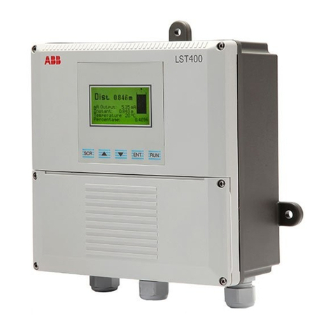
Microcyber FOUNDATION FIELDBUS NCS-TT106F User manual

NCS-TT106F
FOUNDATION FIELDBUS series
Intelligent Temperature Transmitter
User Manual

http://www.microcyber.cn/en
~ I ~
Waring
1. It is forbidden for users to disassemble the temperature module by themselves.
2. Please check if the supply voltage of temperature transmitter meets the power supply voltage requirements in
the manual.
Version
:
V1.0
Disclaimer
The contents of this manual have been checked to confirm the consistency of the hardware and software described.
Since errors cannot be completely ruled out, absolute consistency cannot be guaranteed. However, we will regularly
check the data in this manual and make necessary corrections in subsequent versions. Any suggestions for
improvement are welcome.
Microcyber Corporation 2020
Technical data is subject to change.

http://www.microcyber.cn/en
~ II ~
Company Introduction
Microcyber Corporation,established as a high-tech enterprise by the Shenyang Institute of Automation Chinese
Academy of Sciences, mainly engages in advanced industrial control systems, equipments, instruments and chips
for industrial process automation control solutions in the research, development, production and application.
Microcyber undertakes a number of national scientific and technical key task and “863” project, and has Liaoning
Province networked control systems engineering research center.
Microcyber successfully developed the FF H1 fieldbus protocol stack which is number one to be approved
internationally in China, and the Industrial Ethernet Protocol(HSE) which is number one to be approved in China,
and the domestic first fieldbus instrument which has a function of national-level intrinsically safe explosion--proof
and safety barrier. Also Microcyber participated in the drafting of the domestic first Ethernet-based industrial
automation protocol standards (Ethernet for Plant Automation, EPA). As a result, serial products are composed of
configuration, control software, embedded software, control system, instrument chip to the OEM board, and make
Microcyber be an industrial automation products provider in full range, and also further Microcyber‟s leading
position in the field of fieldbus technology.
Microcyber is the member of FieldComm Group(FCG) and Profibus National Organization (PNO) .
Microcyber passes the Authentication of ISO 9001 Quality System, and has an outstanding innovative R&D team,
plentiful practical experiences of design of the Automatic engineering, a leading product series, a huge market
network, a strict quality management system and an excellent enterprise culture. All these further a solid
foundation of entrepreneurship and sustainable development for Microcyber.
Carrying the ideals of employees, creating customer value and promoting enterprise development.

http://www.microcyber.cn/en
~ III ~
CATALOGUE
1 OVERVIEW ........................................................................................................................................................... 1
2 TEMPERATURE TRANSMITTER INSTALLATION ..................................................................................................... 2
2.1 DIMENSIONS ............................................................................................................................................................ 2
2.2 INSTALLATION ........................................................................................................................................................... 2
2.3 WIRING .................................................................................................................................................................. 4
3 FOUNDATION FIELDBUS PROTOCOL TEMPERATURE TRANSMITTER CONFIGURATION ....................................... 5
3.1 TOPOLOGY CONNECTION ............................................................................................................................................ 5
3.2 FUNCTION BLOCK ...................................................................................................................................................... 6
3.3 TRANSDUCER BLOCK CONFIGURATION EXAMPLE .............................................................................................................. 6
3.3.1 Connecting a resistance sensor ................................................................................................................... 6
3.3.2 Connect RTD thermal resistance sensor ...................................................................................................... 7
3.3.3 Connect-/ + 100mV signal sensor ................................................................................................................ 7
3.3.4 Connect TC Thermocouple Sensor .............................................................................................................. 7
3.3.5 Custom TC thermocouple sensor ................................................................................................................ 7
3.3.6 Custom RTD thermal resistance sensor ....................................................................................................... 8
3.4 FUNCTION CONFIGURATION ........................................................................................................................................ 8
3.4.1 Setting up the configuration environment .................................................................................................. 9
3.4.2 Import DD file .............................................................................................................................................. 9
3.4.3 Device online detection ............................................................................................................................. 10
3.4.4 Sensor configuration .................................................................................................................................. 10
3.4.5 Two-wire zero calibration configuration .................................................................................................... 11
3.4.6 Two-point linearization calibration ............................................................................................................ 12
3.4.7 Multipoint linearization calibration ........................................................................................................... 13
3.4.8 Enabling cold junction temperature compensation .................................................................................. 14
3.5 FUNCTION BLOCK CONFIGURATION ............................................................................................................................. 15
4 MAINTENANCE .................................................................................................................................................. 20
5 TECHNICAL SPECIFICATIONS .............................................................................................................................. 21
5.1 BASIC PARAMETERS ................................................................................................................................................. 21
5.2 THERMAL RESISTANCE TECHNICAL INDEX ...................................................................................................................... 21
5.3 THERMOCOUPLE TECHNICAL INDICATORS ..................................................................................................................... 22
5.4 PHYSICAL CHARACTERISTICS ...................................................................................................................................... 22

http://www.microcyber.cn/en
~ 1 ~
1 Overview
NCS-TT106F intelligent temperature transmitter adopts field bus technology, is a new generation of intelligent
temperature transmitter, is an indispensable field device in process control. The device integrates a wealth of
functional modules, which can achieve both general detection functions and complex control strategies.
NCS-TT106F adopts digital technology and can be applied to a variety of thermal resistance and thermocouple
sensors. It has a wide measuring range and a simple interface between the field and the control room.
NCS-TT106F series intelligent temperature transmitter supports Foundation Fieldbus protocol, which can be widely
used in petroleum, chemical, electric power, metallurgy and other industries.

http://www.microcyber.cn/en
~ 2 ~
2 Temperature transmitter installation
2.1 Dimensions
Figure 2.1 Dimension of Temperature Transmitter(Unit:mm)
2.2 Installation
Fix the temperature transmitter into the temperature housing or din rail by positioning the two screws through the
positioning hole.
36
33
5
Φ5. 5
Φ24
Φ45
1
3
2
45
6
21
23
13
110
99
NCS-TT106F-R1
5+ 6- 8N7S
1 2 3 4
5 6 7 8

http://www.microcyber.cn/en
~ 3 ~
Figure 2.2 Installation
12
2
1
OFF
ON

http://www.microcyber.cn/en
~ 4 ~
2.3 Wiring
Figure 2.3 Wiring
The power supply of NCS-TT106F temperature transmitter and bus signal share a pair of cables, called bus cable. It
is recommended to use the fieldbus dedicated cable recommended by IEC61158-2. The signal cable and bus cable
should not share the conduit or open channel with the power cables of other equipment, and should be far away
from high-power equipment. The shielded wires at both ends of the bus are grounded by single-ended grounding.
-
+
2
1
Connect to the bus and
provide bus power
1
3
2
45
6
TC,mV
2-wire
RTD Ω
3-wire
RTD Ω
4-wire
RTD Ω
-
+
NCS-TT106F
+
-
Connect to the bus
and provide bus power
TC,mV
2-wire
RTD Ω
3-wire
RTD Ω
4-wire
RTD Ω
-
+
4
3
2
1
8
7
6
5
NCS-TT106F-R1
2
1

http://www.microcyber.cn/en
~ 5 ~
3 Foundation Fieldbus Protocol Temperature Transmitter Configuration
3.1 Topology Connection
Foundation Fieldbus transmitter supports multiple network topology wiring methods, as shown in Figure 3.1 Figure
3.2 shows the bus connection of the FOUNDATION FIELDBUS transmitter. Both ends of the bus need to be
connected with terminal matching resistors to ensure signal quality. The maximum length of the bus is 1900 meters,
and it can be extended to 10 kilometers by using repeaters.
Figure 3.1 Foundation Fieldbus network topology
Figure 3.2 Foundation Fieldbus bus connection
Point to Point Bus with branch Daisy chain Tree type
Parameterized configuration tool
NCS-TT106F NCS-TT106F NCS-TT106F NCS-TT106F NCS-TT106FNCS-TT106FNCS-TT106FNCS-TT106F
Control master station
Fieldbus I/O
FOUNDATION FIELDBUS
Junction box
Terminator
Fieldbus
power supply
Master
device
FF bus FF bus
Max 1900m
NCS-TT106FNC S-TT10 6F
NCS-TT106F
Terminator

http://www.microcyber.cn/en
~ 6 ~
3.2 Function block
The FOUNDATION FIELDBUS type NCS-TT106F temperature transmitter implements the FOUNDATION FIELDBUS
standard function block, see the table below. For the configuration method of the function block, please refer to
the FOUNDATION FIELDBUS protocol related documents.
Name
Description
Resource Block
Resource block, used to describe the characteristics of field devices, such as
device name, manufacturer, and serial number. The resource block has no input
or output parameters. A device usually has only one resource block
TEMP_SENSOR 1(TTB)
Transducer block, read the sensor hardware data, or write the field data to the
corresponding hardware. Transducer block contains information such as range,
sensor type, linearization, I / O data, etc.
CUSTOM_BLOCK1(CTB)
Transducer block, expand the function of transducer block 1, mainly to
complete the user's secondary calibration and user-defined sensor type
function
AI 1(AI)
Analog Input function block 1 (AI 1). Obtain the analog process value from the
transducer block through the internal channel, process it, and provide the
appropriate measured value to the master device through bus communication
AI 2(AI)
Analog Input function block 2 (AI 2). Obtain the ambient temperature value
from the transducer block through the internal channel and process it, and
provide the appropriate measured value to the master device through bus
communication
PID1(PID)
Proportional-Integral-Derivative function block (PID). Use this function block to
realize the split-range control process
3.3 Transducer block configuration example
NCS-TT106F temperature transmitter can connect various types of sensors, such as resistance sensor, RTD thermal
resistance sensor, TC thermocouple sensor, -/ + 100mV signal, custom RTD thermal resistance sensor and custom
TC thermocouple sensor. The following describes the connection and configuration of each type of sensor.
3.3.1 Connecting a resistance sensor
NCS-TT106F temperature transmitter can measure 0-500Ω and 0-4000Ω resistance signals. When the resistance
signal sensor is connected, the parameters in the transducer block are configured as follows:
SENSOR_TYPE = 0-500Ω or 0-4000Ω
SENSOR_CONNECTION = Two Wires or Three Wires or Four Wires
PRIMARY_VALUE_UNITS_INDEX = Ohm or kOhm
RJ_TYPE = N/A(ignore)

http://www.microcyber.cn/en
~ 7 ~
3.3.2 Connect RTD thermal resistance sensor
SENSOR_TYPE = CU50 or CU100 or PT100 or PT1000
SENSOR_CONNECTION = Two Wires or Three Wires or Four Wires
PRIMARY_VALUE_UNITS_INDEX = K or
℃
or
℉
or °R
RJ_TYPE = N/A(ignore)
3.3.3 Connect-/ + 100mV signal sensor
SENSOR_TYPE = -/+100mV
SENSOR_CONNECTION = Two Wires
PRIMARY_VALUE_UNITS_INDEX = mV
RJ_TYPE = N/A(ignore)
3.3.4 Connect TC Thermocouple Sensor
SENSOR_TYPE = T/CType B or T/CType E or T/CType J or T/CType K
T/CType N or T/CType R or T/CType S or T/CType T
SENSOR_CONNECTION = Two Wires
PRIMARY_VALUE_UNITS_INDEX = K or
℃
or
℉
or °R
RJ_TYPE = No reference or Internal or External or External PT100
3.3.5 Custom TC thermocouple sensor
SENSOR_TYPE = Custom defined TC
SENSOR_CONNECTION = Two Wires
PRIMARY_VALUE_UNITS_INDEX = K or
℃
or
℉
or °R
RJ_TYPE = No reference
For custom TC thermocouple sensor measurement, you need to enter the polynomial value in the custom TC
parameter in the transducer block CUSTOM_BLOCK1 and the temperature value measured by the calculation
formula. The following is an example of measuring a custom TC thermocouple sensor.
CUSTOM_TC_NAME = Custom TC Example
CUSTOM_TC_POLY_COUNT = 5
CUSTOM_TC_MIN_IN = -6500.0
CUSTOM_TC_MIN_OUT = -100.0
CUSTOM_TC_MAX_OUT = 1200.0
Example of custom TC thermocouple sensor polynomial coefficients

http://www.microcyber.cn/en
~ 8 ~
CUSTOOM_TC_POLY_X
max.input
limit in μV
for
POLY_X
4th degree
coefficient
for
POLY_X
3th degree
coefficient
for
POLY_X
2th degree
coefficient
for
POLY_X
1st degree
coefficient
for
POLY_X
0degree
coefficient
for
POLY_X
CUSTOM_TC_POLY_1
-3200.0
-3.84E-13
-5.65E-9
-3.36E-5
-6.10E-2
-8.44E1
CUSTOM_TC_POLY_2
3500.0
-8.13E-15
7.29E-11
-4.18E-7
2.53E-2
-1.08E-2
CUSTOM_TC_POLY_3
10000.0
-1.35E-15
1.50E-11
1.41E-7
2.26E-2
4.18
CUSTOM_TC_POLY_4
30000.0
3.49E-18
2.19E-12
-1.53E-7
2.68E-2
-9.26
CUSTOM_TC_POLY_5
70000.0
6.27E-17
-8.76E-12
5.34E-7
8.69E-3
1.65E2
3th degree
coefficient
2th degree
coefficient
1st degree
coefficient
0 degree
coefficient
CUSTOM_TC_RJ_POLY
-1.11E-4
2.65E-2
3.94E1
3.94E-1
For example, the input voltage of the TC terminal of the temperature transmitter is 5000 μV and the temperature
of the cold terminal is 25 ° C. According to the formula, the voltage value corresponding to the temperature of the
cold terminal can be calculated:
URJ = 3.94 * 10-1 + 3.94 * 101 * 25 + 2.65 * 10-2 * 252 - 1.11 * 10-4 * 253 = 1000 μV
Add this voltage to the input terminal of TC (5000 + 1000) and then calculate the corresponding temperature value
according to the calculation formula:
4.18 + 2.26 * 10-2 * 6000 + 1.41 * 10-7 * 60002 + 1.50 * 10-11 * 60003 - 1.35 * 10-15 * 60004 = 146.3 °C
3.3.6 Custom RTD thermal resistance sensor
SENSOR_TYPE = Custom defined RTD
SENSOR_CONNECTION = Two Wires or Three Wires or Four Wires
PRIMARY_VALUE_UNITS_INDEX = K or
℃
or
℉
or °R
RJ_TYPE = No reference
Custom RTD thermal resistance sensor measurement, you need to enter the value of the polynomial in the custom
RTD parameter in the transducer block CUSTOM_BLOCK1, and the temperature value measured by the calculation
formula. You can refer to the way of custom TC to set.
3.4 Function configuration
NCS-TT106F intelligent temperature transmitter supports all mainstream FOUNDATION FIELDBUS master system
(NI-FBUS Configurator of NI company, DeltaV of EMERSON, EN2FFR-1788 of Rockwell and other general
FOUNDATION FIELDBUS configuration software) on the market for configuration . The following mainly uses NI
company's NI-FBUS Configurator configuration software as an example to introduce the configuration and use
method of NCS-TT106F temperature transmitter.

http://www.microcyber.cn/en
~ 9 ~
3.4.1 Setting up the configuration environment
1) PC, the operating system is Windows XP, Windows7 or Windows10;
2) NI USB-8486,H1 bus power supply, H1 terminator;
3) NI-FBUS Configurator;
As shown in Figure 3.3 below is a demonstration environment built using NI's BUS-8486 as an example.
Figure 3.3 NCS-TT106F hardware test environment
3.4.2 Import DD file
Open the Interface Configuration Utility software in the NI software and import it according to the steps shown in
Figure 3.4 below. After successful DD import, there will be a successful prompt.
24VDC powe r supply
Computer
+
-
NCS-TT106F
NI USB-8486
FF bus power supply and
terminal matcher
BUS
PT100 sensor
①
②
③

http://www.microcyber.cn/en
~ 10 ~
3.4.3 Device online detection
According to the wiring diagram of NCS-TT106F, connect the two lines FF + and FF- to the FOUNDATION FIELDBUS
bus. Open the NI-FBUS Configurator software, and the NCS-TT106F device will be detected on the interface. As
shown in Figure 3.5 below. In the figure, NCS-TT106F has one resource block, 2 transducer blocks, 2 AI function
blocks and 1 PID function block.
Figure 3.5 The device goes online normally
3.4.4 Sensor configuration
When using the NCS-TT106F temperature transmitter, the related parameters should be configured in the
transducer block according to the connected sensor model. Open the transducer block TEMP_SENSOR1, change
the TARGET in the MODE_BLK parameter of the transducer block to OOS, and configure the sensor type and
connection cable system under the SENSOR_TYPE and SENSOR_CONNECTION lists. Take the PT100 three-wire
system as an example in Figure 3.6 below.
④
Figure 3.4 DD import interface

http://www.microcyber.cn/en
~ 11 ~
Figure 3.6 Sensor configuration
After the configuration is completed, modify the TARGET in the MODE_BLK parameter of the transducer block to
Auto, and the ACTUAL parameter in the MODE_BLK parameter should be Auto, otherwise modify the configuration
according to the prompt of the BLOCK parameter. You can see the current temperature value and status collected
by the PT100 sensor in the PRIMARY_VALUE parameter. As shown in Figure 3.7 below.
Figure 3.7 Temp erature meas urement val ue d isplay inte rface
3.4.5 Two-wire zero calibration configuration

http://www.microcyber.cn/en
~ 12 ~
In the two-wire measurement, the two-wire zero calibration can be performed by the
TWO_WIRES_COMPENSATION parameter of the transducer block. The specific method is as follows:
First, give the channel zero value, that is, short the two ends of the channel.
Secondly, set the parameter TWO_WIRES_COMPENSATION to Start, click the "Write Changes" button.
Finally, after successful writing, read the TWO_WIRES_COMPENSATION parameter and click the "Read All" button
until the two-wire zero calibration is successful when the value of this parameter is Finish.
3.4.6 Two-point linearization calibration
NCS-TT106F temperature transmitter has undergone rigorous calibration work before leaving the factory, in general,
no user calibration is required. Users can use parameters CAL_POINT_HI, CAL_POINT_LO, and CAL_UNIT to achieve
two-point linearization calibration. The following uses mV signal two-point linearization calibration as an example.
The operation steps are as follows:
(1)Set the TEMP_SENSOR1 MODE parameter of the transducer block to OOS, and set the SENSOR_TYPE
parameter to-/ + 100mV. Set the calibration unit parameter CAL_UNIT to mV according to the sensor type, and set
the parameter SENSOR_CAL_METHOD to “User Trim Standard Calibration”. The setting diagram is shown in Figure
3.8 below.
Figure 3.8 Two-point linearization calibration configuration diagram
(2)Calibrate the lower limit mV signal to the acquisition channel through the standard mV signal source. After
stabilization, write the output value of the standard mV signal source to the CAL_POINT_LO parameter and click
the "Write Changes" button. Similarly, the standard mV signal source is used to output the upper calibration mV

http://www.microcyber.cn/en
~ 13 ~
signal to the acquisition channel. After stabilization, write the output value of the standard mV signal source to the
CAL_POINT_HI parameter and click the "Write Changes" button. No prompt for writing errors indicates that the
calibration was successful. As shown in Figure 3.9 below, the lower limit of the calibration mV signal is -80mV, and
the upper limit of the calibration mV signal is 80mV. Note that the written calibration data and the actual input
channel data must not have a large deviation, otherwise the calibration will fail.
Figure 3.9 Two-point linearization calibration configuration diagram
After completing the above steps, set the TEMP_SENSOR1 MODE parameter of the transducer block to Auto, and
mV signal acquisition can be performed normally. BIAS is the offset parameter, and the offset function is valid in
this mode. In Celsius, the two-point linearization calibration principle of the ohmic signal is the same as the
calibration principle of the mV signal.
3.4.7 Multipoint linearization calibration
NCS-TT106F temperature transmitter has the function of multi-point linearization calibration. It can support up to
16 calibration points. The user can choose whether to enable it according to his needs. Through the calibration
parameters TAB_X_Y_VALUE1-TAB_X_Y_VALUE16 of the CUSTOM_BLOCK1 transducer block, the user can
complete the multi-point linear calibration of the instrument by himself. The calibration procedure is as follows:
(1)The NCS-TT106F temperature transmitter provides 16 calibration point inputs, namely the TAB_X_Y_VALUE1-
TAB_X_Y_VALUE16 array of parameters of the transducer block. The user can write the output values to be
calibrated into the array in turn and select a good unit. For example, when performing three-point interpolation
calibration, the user can select 10, 20, and 30 as calibration points, and write the three values in the second place
in the TAB_X_Y_VALUE1, TAB_X_Y_VALUE2, and TAB_X_Y_VALUE3 arrays, as shown in Figure 3.10.

http://www.microcyber.cn/en
~ 14 ~
Figure 3.10 Calibration point configuration
(2)Input the standard signal through the standard source, and open the transducer block TEMP_SENSOR1 in the
configuration software, read the value of the parameter PRIMARY_VALUE, and write the value to the first place in
the TAB_X_Y_VALUE1, TAB_X_Y_VALUE2, and TAB_X_Y_VALUE3 arrays. For example, write the read 10.2, 20.5, 30.4
in the array, and set the parameter ENABLE_TAB_X_Y to "Enable" as shown in Figure 3.11. This is the end of
calibration work.
Figure 3.11 Acquisition parameter configuration
(3) Open the transducer block TEMP_SENSOR1, set the MODE parameter to OOS, and set the parameter
SENSOR_CAL_METHOD to “User Trim special Calibration”. After successful setting, set the MODE parameter to Auto,
and the temperature transmitter will work according to the calibrated characteristic curve.
3.4.8 Enabling cold junction temperature compensation
When using the thermocouple as the sensor, the user can set the cold junction compensation through the

http://www.microcyber.cn/en
~ 15 ~
parameter RJ_TYPE, and set it to Internal to enable the internal cold junction compensation. At this time, the value
of RJ_TEMP is the temperature value measured internally, that is, the value of the parameter SENCANDARY_VALUE;
External can configure a fixed cold junction compensation value by setting the value of EXTERNAL_RJ_VALUE. At
this time, the value of RJ_TEMP is the value of EXTERNAL_RJ_VALUE; when it is set to External PT100, the
temperature can be measured by an external two-wire PT100 sensor as the cold junction compensation value;
setting No reference can disable cold junction compensation, as shown in Figure 3.12.
Figure 3.12 RJ_TYPE configuration
3.5 Function block configuration
NCS-TT106F temperature transmitter has 2 AI function blocks and a PID function block, each function block
conforms to the FOUNDATION fieldbus standard. When NCS-TT106F temperature transmitter is applied in
engineering, it needs to be configured and configured And download function blocks to complete temperature
collection and logic control. The following takes the configuration of the AI function block as an example for detailed
description. The specific configuration steps are as follows:
(1)After ensuring that the NCS-TT106F transducer block is configured correctly and are in Auto mode, open the
"Function Block Application" configuration interface in the NI software, drag the AI1, AI2, and PID function blocks
into the configuration interface to connect AI1 and AI2 OUT to PID IN and CAS_IN respectively. As shown in Figure
3.13 below.

http://www.microcyber.cn/en
~ 16 ~
Figure 3.13 Function block configuration diagram
(2)To download the configuration information, click the "Download Project" button on the NI software to
download the configuration project. The download interface is shown in Figure 3.14 below.
Figure 3.14 Configuration engineering download interface
(3)After the configuration information is downloaded successfully, you need to configure the parameters in the
AI function block. Common configuration parameters are CHANNEL, XD_SCALE, OUT_SCALE, and L_TYPE. Let's take
the AI1 function block as an example for configuration, open the AI1 function block, modify the TARGET in the
MODE_BLK parameter to OOS, modify the upper and lower limits and unit parameters of XD_SCALE, modify
CHANNEL to Primary Value, modify L_TYPE to Direct, and click "Write Changes" The button finishes writing the
modified parameters. As shown in Figure 3.15.
Table of contents
Other Microcyber Transmitter manuals
