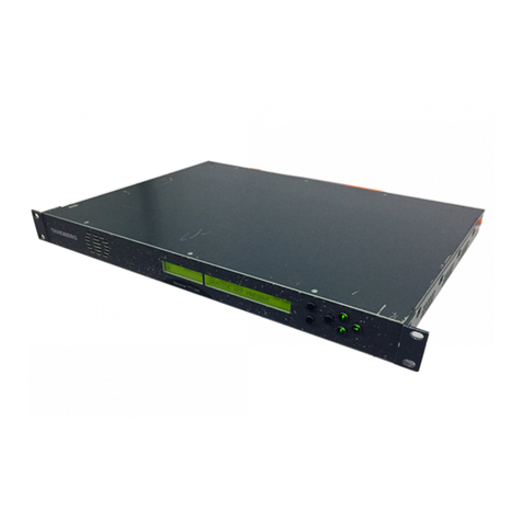
Microdyne 1100-AR Series User manual

Courtesy of http://BlackRadios.terryo.org

Revised: 5/16/73
r
i
r
'
r
r
j
Instruction Manual
MODEL 1100-AR TELEMETRY RECEIVER
S/N 399 and above
July 1972
TRADE SECRETS
The information contained in/on this document constitutes trade
secrets of Microdyne Corporation and, therefore, the user of this infor
mation covenants and agrees that he/it will not, nor will he/it cause
others to copy or reproduce said information, either in whole or in
part, or manufacture, produce, sell or lease any product copied from or
essentially based upon the information contained herein without prior
written approval of Microdyne Corporation.
MICR0DYNE
WC
POST OFFICE BOX 1527 ROCKVILLE, MD. 20850
Telephone (301) 762-8500
Courtesy of http://BlackRadios.terryo.org

1100-AR
rr
•
f
r-
"
i
ir
i
J
SAFETY PRECAUTIONS
The following are general safety precautions that are not related to any specific procedures
and therefore do not appear elsewhere in this publication. These are recommended pre
cautions that personnel must understand and apply during many phases of operation and main
tenance.
HIGH VOLTAGE
Operating and maintenance personnel must at all times observe all safety precautions. Care
must be exercised when performing maintenance in and round the line filter, the power trans
former, and the front panel. Line voltage is present in the vicinity of the power connector
J17, the Audio Gain/Operate Mode switch on the front panel, pins 1, 3, 4, 5 of the power
transformer and pins 13, 14, 16, 17 of XA21 front panel connector.
DO NOT SERVICE OR ADJUST ALONE
Maintenance personnel should not service or adjust the equipment except in the presence of
someone who is capable of rendering aid.
RESUSCITATION
Personnel working with or near high voltages should be familiar with modern methods of re
suscitation. Such information may be obtained from the Bureau of Medicine and Surgery.
'
Courtesy of http://BlackRadios.terryo.org

1100-AR
ERRATA
Insert the following pen and ink corrections into the basic manual prior to using it to service
the 1100-AR Receiver.
Replaceable Parts List:
Base Chassis; paragraph 6-3.
Change: C14 from 30 /iF to 800 pF, 16V
R13 from part of S2 to part of S3.
Base Chassis; paragraph 6-4.
Add: C14, 800 pF, 16V
C15, 0.33 uF, 100V
C16, 0.33/iF, 100V
Change: R13 from part pf S2 to part of S3.
Replaceable Parts List, Base Chassis/Figure 7-2:
Add current limiting resistors, R25 and R26. 10 ohms, i watt, between
the CR2 (-) and the R17-C12-C13, and between CR2 (+) and C10.
E-l
Courtesy of http://BlackRadios.terryo.org

1100-AR
"
r
i
r
INTRODUCTION
This instruction manual provides operation and maintenance information for the Model 1100-AR
Telemetry Receiver designed and manufactured by Microdyne Corporation. The 1100-AR is a
highly adaptable, completely modularized receiver which can be easily integrated into ground
station and laboratory applications by simply selecting the module complement on order.
Being extremely versatile, the 1100-AR can be easily configured as a low cost general purpose
receiver supplying the minimum number of outputs, or as a complex data receiver with prede-
rtection record and playback capabilities, automatic search and lock for signal acquisition, and
spectrum analysis by simply selecting the module complement. An example of the receiver's
versatility is readily apparent with the two types of rf tuners and i-f filter/amplifiers now
available. These modules can be supplied in electro-mechanically and fixed tuned versions or
in voltage tuned versions. The advantage of voltage tuned versions is that a receiver equipped
with these modules can be controlled in frequency and bandwidth by analog inputs from a com
puter or remote console allowing for completely automated ground stations. Electro-
mechanically and fixed tuned versions, while not being able to be computer controlled, offer
the same signal handling capabilities and operating parameters as the voltage tuned models.
Another feature which proves advantageous under certain conditions but relatively superfluous
in others is the anti-sideband lock option of the wide angle phase demodulators. This feature
prevents the receiver from locking on a sideband of a phase modulated carrier during the re-
acquisition cycle in applications where signal dropout is expected and frequent. Thus, opera
tor time expended in monitoring receiver status or manually reacquiring phaselock is reduced
to an absolute minimum. The receiver afc system may also be "tailored to fit" customer re-
rquirements with two types of afc circuits available. One circuit is a low cost unit which pro
vides automatic frequency control only. The second type, being more complex, not only pro
vides automatic frequency control but also automatically sweeps an adjustable search range
upon loss of signal. This sweeping function continues until a signal of sufficient strength ap
pears in the i-f passband at which time lock is automatically resumed.
Because of the many combinations of modules available for the 1100-AR, this manual is con
structed to be readily adaptable to any receiver configuration. It is composed of nine indi
vidual sections preceded by a module complement page and contents pages. The module com
plement page is checked according to which modules are supplied in the associated receiver
configuration. Using the information presented on this page, Sections I through VII can be
modified as required to match the receiver. For example, if the applicable receiver does not
contain predetection playback or record capabilities, the information pertaining to these items
can be designated as not applicable. Similarly, should the receiver be equipped with the afc
search and lock capability, only the portion of the afc system description dealing with that par
ticular configuration need be applied. Maintenance procedures, replacement parts lists, and
schematic diagrams are adapted in a like manner.
Manuals supplied for special receivers which have been slightly modified to meet particular
requirements contain a Section VIII. This section thoroughly describes the modification and
the effects it has on overall operating procedures and parameters. Also included in this sec
tion are any special instructions for modifying operating and maintenance procedures, parts
lists, and schematic diagrams.
Courtesy of http://BlackRadios.terryo.org

1100-AR
The final portion of this manual is Section IX. This section is composed of the instruction
booklets for each plug-in module or a group of related modules excluding front panel plug-in
modules. Included in each booklet is the theory of operation, special mounting procedures,
repair and alignment procedures, parts lists, and schematic diagrams. The number of book
lets contained in this section depends upon the module complement of the associated receiver.
Front panel modules, because of their complexity, are supplied with a complete instruction
manual. These manuals are provided as supplements to this manual and may or may not be
bound in this volume.
1
1
1
m
1
l
1
1
Courtesy of http://BlackRadios.terryo.org

'J 1100-AR
r
r
■
r
r
r
r
r
MODULE COMPLEMENT
The receiver for which this manual is supplied contains the following modules:
Narrow
•
/
/
■~-
/
y
First IF Filter s Wide Int.
F i r s t I F F i l t e r ( S w i t c h a b l e ) W i d e / I n t . / N a r r o w
Second Mixer
Second LO / c x °
AM Detector
Video Amplifier
AGC Amplifier
Metering Amplifier
AFC Amplifier (AFC/Search & Lock)
AFC Amplifier (AFC only)
Calibration/Reference Oscillator
kHz Record Converter (10-1100 Series)
kHz Playback Converter (20-1100 Series)
10 MHz Playback Converter (30-1100)
SDU Converter
Video Filter #
Video Filter # x-
Special Video Filter _
Display Regulator
1st IF/SDU Amplifier
Courtesy of http://BlackRadios.terryo.org

1100-AR
rr.
-I
r
r
r
t
r
i
r
TABLE OF CONTENTS
Section Title Page
I GENERAL INFORMATION
1-1. Scope 1-1
1-2. Purpose and Description 1-1
1-7. Base Chassis 1-1
1-8. Front Panel 1-1
1-9. RF Tuner 1-2
1-10. Demodulators 1-2
1-11. Second IF Filter/Amplifiers 1-2
1-12. First IF Filter 1-2
1-13. Second Mixer 1-2
1-14. Second Local Oscillator 1-2
1-15. AM Detector 1-3
1-16. Calibrate/Reference Oscillator 1-3
1-17. Video Filters 1-3
1-18. Video Amplifier 1-3
1-19. AGC Amplifier 1-3
1-21. Metering Amplifier 1-3
1-22. AFC Amplifier 1-4
1-23. Playback Converter 1-4
1-24. Record Converter 1-4
1-25. Display Converter 1-4
1-26. Spectrum Display Unit 1-4
1-27. Predetection Record Converter 1-4
1-28. Predetection Playback Converter 1-4
1-29. Center Frequency Offset and Auxiliary AGC
Output Modules 1-4
1-31. Reference Tables 1-5
II INSTALLATION
2-1. General 2-1
2-3. Receiving 2-1
2-6. Installation 2-1
2-7. Mounting 2-1
2-9. Interconnecting Cable 2-1
2-11. Primary Power 2-2
2-13. Front Panel Module Installation 2-2
2-16. Front Panel Module Removal 2-2
2-18. Storage and Handling 2-2
2-20. Packaging for Reshipment 2-3
III OPERATION
3-1. General 3-1
3-3. Controls and Indicators 3-1
3-5. Operating Instructions 3-5
continued
Courtesy of http://BlackRadios.terryo.org

1100-AR
Table of Contents, continued
Section Title Page
HI 3-7. Initial Setup and Calibration 3-5
3-9. Control Settings 3-5
3-11. Receive Mode Operation 3-6
3-13. First Local OscUlator 3-6
3-14. Second Local OscUlator 3-7
3-15. Video Gain 3-8
3-16. AGC Time Constant 3-8
3-17. PM Mode Operation 3-8
3-19. PM Mode Operating Precautions 3-8
3-20. Manual Search 3-10
3-21. Automatic Search 3-10
3-22. Playback Mode Operation 3-10
3-24. Computer/Remote Control 3-11
3-26. AGC Recording 3-11
3-28. Turn-Off Procedure 3-12
1
IV THEORY OF OPERATION
4-1. General 4-1
4-3. Primary Signal Paths 4-1
4-5. Normal Signal Flow 4-1
4-22. Predetection Signal Flow 4-3
4-24. Predetection Record Circuit 4-3
4-26. Predetection Playback Circuit 4-7
4-32. Control Signal Flow 4-8
4-34. Automatic Frequency Control (AFC) System 4-8
4-37. Automatic Phase Control (APC) System 4-9
4-42. Automatic Gain Control (AGC) System 4-11
4-48. Video Filters 4-13
4-51. Power Supply 4-14
V M A I N T E N A N C E
5-1. General 5~1
5-3. Required Test Equipment 5-1
5-5. Special Tools and Test Equipment 5-1
5-7. Preoperational Test and Calibration with FM Demodulator .... 5-2
5-9. Preoperational Test and Calibration with
Phase Demodulator 5-5
5-11. AGC Adjustment 5-7
5-14. Preventive Maintenance 5-8
5-16. Visual Operation 5-8
5-19. Lubrication 5-9
5-21. Performance Tests 5-9
5-23. FM Tests 5_9
continued
ii
Courtesy of http://BlackRadios.terryo.org

I
■
1100-AR
Table of Contents, continued
Section Title Page
V 5 - 2 4 . P M T e s t s 5 - 1 1
5-25. Corrective Maintenance 5-13
5-27. Troubleshooting 5-13
5-31. Repair 5-14
5-33. Base Unit 5-14
5-34. Front Panel 5-14
5-35. Internal Plug-In Modules 5-14
5-37. Alignment 5-15
V I R E P L A C E M E N T PA R T S L I S T
6-1 General 6-1
6-3 Receiver Base Chassis 6-1
6-4 Base Chassis, 1100-AR(5) 6-4
6-5 Front Panel Subassembly 6-6
6-6 Video Filter #1 6-7
6-7 Video Filter #2 6-8
6-8 Video Filter #3 6-8
6-9 Video Filter #4 6-9
6-10 Video Filter #5 6-9
6-11 Video Filter #6 . 6-10
6-12 Video Filter #7 6-11
"
rVII MAINTENANCE DIAGRAMS 7-1
VIII MODIFICATIONS 8-1
IX SUBASSEMBLY MODULES 9-1
Hi/
IV
Courtesy of http://BlackRadios.terryo.org

r
1100-AR
LIST OF ILLUSTRATIONS
Figure Title Pag^
1-1 Model 1100-AR Telemetry Receiver, Typical Configuration 1-0
2-1 Model 1100-AR Telemetry Receiver, Typical Rear View 2-3
2-2 Power Transformer Strapping 2"7
3-1 Model 1100-AR Telemetry Receiver, Typical Front View 3-1
4-1 Functional Block Diagram 4-5
4-2A AFC Only 4~8
4-2B AFC with Search and Lock 4-9
4-3 Sweep Circuitry, Block Diagram 4-10
4-4 AGC System, Simplified Block Diagram 4-12
7-1 1100-AR Front Panel, Schematic Diagram 7-1
7-2 1100-AR Base Chassis, Schematic Diagram, (Eight Sheets) ...... 7-3
7-3 Video Filter #1, #5, #6, and #7, Schematic Diagram 7-9
7-4 Video Filter #2, #3, and #4, Schematic Diagram 7-10
7-5 Display Regulator, Schematic Diagram 7-11
r
-
r
r
r
LIST OF TABLES
Number Title Page
1-1 Basic Components of the Model 1100-AR Telemetry Receiver 1-5
1-2 Specifications 1-6
2-1 Rear Apron Connectors 2-4
3-1 Controls and Indicators 3-2
3-2 Crystal Determining Formulas 3-7
5-1 Test Equipment Required 5-1
5-2 IF Bandwidth in dB 5-5
5-3 RF Tuner Noise Figure 5-5
Courtesy of http://BlackRadios.terryo.org

1100-AR
L
\
1
Figure 1-1. Model 1100-AR Telemetry Receiver, Typical Configuration 1
1
I,
1
1-0
Courtesy of http://BlackRadios.terryo.org

1100-AR
r
r
'
X
'
|r
SECTION I
GENERAL INFORMATION
1-1. SCOPE. This manual provides information concerning the description, installation,
operation, and maintenance of the Model 1100-AR Telemetry Receiver designed and manu
factured by Microdyne Corporation, Rockville, Maryland. Schematic diagrams and replace
ment parts lists are also included herein.
1-2. PURPOSE AND DESCRIPTION
1-3. The Model 1100-AR Telemetry Receiver is an advanced, solid-state, dual conversion
telemetry receiver making full use of integrated circuits and related subminiature compo
nents. The receiver is capable of receiving and processing any known or projected telem
etry data format transmitted by amplitude, frequency, or phase modulated rf carriers over
the range of 105 MHz to 6000 MHz. Modular construction techniques are used throughout the
receiver for maximum versatility and to reduce maintenance down time.
1-4. The receiver can be supplied in either of two basic configurations designated
1100-AR(5) and 1100-AR. These configurations are identical in all respects with the excep
tion that the 1100-AR includes mounting provisions for a spectrum analyzer and either a pre
detection record or playback converter. Both configurations are composed of a front panel,
base chassis, and the necessary internal and front panel plug-in modules.
1-5. Front panel controls are logically grouped for ease of operation with concentric
switches used in related areas. Lamps are included for indicating the status of certain re
ceiver functions. These lamps illuminate to provide visual indications of whether the re
ceiver is in the receive, playback, or calibration operating mode, whether there is a carrier
present, and whether the automatic search circuits are energized and functioning. Meters
are employed to indicate the video output level, signal level, tuning accuracy, and deviation.
Calibration controls for the meters are located adjacent to the associated meter. Operating-
controls for the various front panel plug-in modules are also contained on the front panels
and are grouped for ease of operation.
1-6. In order to provide a more complete description of the 1100-AR receiver, the various
components of the receiver are described briefly in the following paragraphs. A list of mod
ules available for use with the receiver is given in table 1-1. The electrical, environmental,
and mechanical specifications are given in table 1-2.
1-7. BASE CHASSIS. The base chassis is the main part of the receiver. This section
contains the mounting facilities and connectors for the plug-in modules, the power supply,
and all interconnecting wiring. Connectors for signal inputs and outputs are mounted on the
rear apron and are labeled as to their function and reference designation.
1-8. FRONT PANEL. The front panel of the receiver is considered to be a module. All
operating controls and indicators except for those mounted on the plug-in modules are con
tained on the front panel and connected to the main chassis through a wiring harness and
mating connectors. If need be, a complete front panel can be replaced in a matter of minutes.
1-1
Courtesy of http://BlackRadios.terryo.org

1100-AR
1-9. RF TUNER. A series of rf tuners covering discrete frequency bands is available
for use with the 1100-AR to enable reception of rf carriers ranging from 105 MHz to
6000 MHz. These units are front panel plug-ins and are available in both voltage tuned and
mechanically tuned models. The tuners function to down convert the selected rf input to a
50 MHz i-f signal for further processing. The voltage tuned versions have the additional
capability of being controlled by a voltage input from a remote tuning console or computer
interface.
1-14. SECOND LOCAL OSCILLATOR. This module supplies the 60 MHz l-o signal to the
second mixer. The oscillator may be operated in any one of five modes to supply the re
quired signal. These modes, vfo, crystal, afc, pm, or off, are controlled by a front panel
switch. In the vfo mode, the frequency is controlled by a front panel fine tune control. In
""
1-10. DEMODULATORS. Demodulator modules are avaUable for the processing of fm,
phase, and bi-phase data. FM demodulators comprise three basic units, each of which
covers a certain range of i-f bandwidths. A narrow band unit covers up to and including
50 kHz, and intermediate and wide band units cover ranges of 100 kHz to 750 kHz and 750 kHz
to 6 MHz. In addition, the intermediate and wide band units or all three ranges can be sup
plied in a single housing. The wide angle phase demodulator may be used with any i-f band
width and is capable of retrieving pm data having peak deviations up to 2.8 radians. This
module may be equipped with an option anti-sideband lock feature which effectively prevents
sideband lock on signal acquisition. A bi-phase demodulator is available for use with i-f
bandwidths exceeding 100 kHz. Capabilities of this unit include demodulation of a ±90 PSK,
bi-phase modulated signal at bit rates between 1 bit and 2 megabits, NRZ. It also is
equipped with the anti-sideband lock feature.
1
1-11. SECOND IF FILTER/AMPLIFIERS. The second i-f filter/amplifier front panel
plug-in modules are employed to establish the bandwidth of the 10 MHz second i-f signal.
Both fixed and variable bandwidth units are available. Each of the fixed bandwidth models ^ TL
sets a single bandwidth in the range of 10 kHz to 6 MHz. Up to three of these filter/
amplifiers can be installed in a module housing to enable multi-bandwidth operation. Mod
ules of this type are equipped with a front panel selector switch. Variable bandwidth models
are voltage tuned and are equipped with a front panel dial to permit selection of any i-f band
width within its operating range. One such unit is the Model 1120-VI(600) which is capable
of setting any bandwidth from 100 kHz to 600 kHz.
1-12. FIRST IF FILTER. The first i-f fUter space in the receiver may be equipped with
any one of three types of modules as selected by the customer on order. The first type of
module supplies steep skirted filtering of the first i-f signal and establishes either a
600 kHz, 1. 2 MHz, or 4 MHz bandwidth. The second type contains any two of the standard
or special bandwidths and is automatically switched by the second i-f filter/amplifier. Both
of these modules supply an isolated 50 MHz output for display purposes. The third type of
module supplies no filtering whatsoever but provides a 50 MHz output for display purposes.
\
1-13. SECOND MIXER. The second mixer accepts the 50 MHz first i-f input and a 60 MHz
second local oscUlator input, and provides a 10 MHz second i-f output. When the receiver
is used in the playback configuration, the 50 MHz pre-recorded signal is injected into the
second mixer and processed identically to the normal first i-f signal.
"*
1-2
Courtesy of http://BlackRadios.terryo.org

"
f
I
'
*
■
I
r
-
r
1100-AR
the afc and pm modes, the frequency is controlled by a voltage generated by afc circuitry
or the phase demodulator (pm). When set to the crystal mode, a fixed 60 MHz signal is gen
erated. The off position permits the injection of an external 60 MHz input.
1-15. AM DETECTOR. An a-m detector module is employed in the 1100-AR to detect any
a-m data, derive the raw age voltage for gain control, and provide both linear and limited
10 MHz outputs for recording.
1-16. CALIBRATE/REFERENCE OSCILLATOR. The calibrate/reference oscillator is an
optional module for receivers equipped with an fm demodulator and a required module for
receivers equipped with a pm demodulator. The 10 MHz output of the module is employed to
calibrate fm systems and serves as a reference for pm systems.
1-17. VIDEO FILTERS. The video filters are employed in the receiver to establish the
video cutoff frequency. Any two of seven video filter modules can be included in the 1100-AR
main chassis. Each of the modules contains a number of video filter circuits in various com
binations as selected by the customer. Selection of which filter used is made through a front
panel switch. In addition, a third filter can be installed to establish a special or non-standard
cutoff frequency as specified by the customer.
1-18. VIDEO AMPLIFIER. The detected and filtered video signal is amplified by this mod
ule and coupled to a rear apron connector. A second output of this module also drives the
front panel output meter. The gain of the video amplifier is adjustable through a front panel
control.
1-19. AGC AMPLIFIER. The age amplifier contains three separate circuits: an age ampli
fier, an age output amplifier, and a carrier operated relay (COR). The age amplifier circuit
is driven by an output from the a-m detector and is used to control the gain of the tuner, sec
ond mixer, and second i-f filter/amplifier. This amplifier circuit also feeds the signal level
meter on the front panel of the receiver. Various age time constants from 0.1 milliseconds to
1 second are selectable through a front panel switch. The output voltage can also be manually
set to the desired level through a selector switch and potentiometer.
1-20. The age output amplifier circuit is used to amplify the output of the age amplifier cir
cuit and feed it to a rear panel connector. Signals appearing at this connector can then be re
corded or applied to combining equipment as required. The COR circuit is also driven by the
age amplifier circuit. This relay causes a front panel lamp to light when the receiver carrier
is above preset threshold level. A double set of single pole double throw relay contacts (ap
pearing at a rear panel connector) is also provided by the COR. These contacts operate when
the front panel carrier lamp lights and may be used to control remote indicators.
1-21. METERING AMPLIFIER. The metering amplifier module supplies the drive voltages
to the receiver deviation and output meters. These voltages are initially derived from the
plug-in demodulator and video amplifier, respectively. Also contained in the metering ampli
fier module is a bridge amplifier circuit. This stage is employed to regulate the oven temper
ature when a crystal oven is installed in the tuner.
1-3
Courtesy of http://BlackRadios.terryo.org

1100-AR
1-22. AFC AMPLIFIER. Two types of afc modules may be utilized with the 1100-AR. One
type supplies afc voltages only. The second type contains automatic sweep circuitry in addi
tion to the normal afc circuit. The automatic sweep circuit is employed in both the afc and
pm modes of operation to generate search voltages to the second l-o to enable automatic
search and lock after signal dropout. Outputs are also provided to control the search indi
cator lamp and to drive the tuning meter.
1-23. PLAYBACK CONVERTER. Two types of playback converters are avaUable for use
with the 1100-AR. These are designated 20-1100 series and 30-1100 series. When a re
ceiver is equipped with a 20-1100 series, any one of the six standard video record carriers
is up converted to 50 MHz and injected into the second mixer. When the receiver is
equipped with a 30-1100 series converter, a 10 MHz signal is up converted to 50 MHz and
injected into the second mixer.
1-24. RECORD CONVERTER. The record converters designed for use with the 1100-AR
are designated 10-1100 series. There are six standard modules available, each of which
supplies a single video record carrier output taken from a rear apron connector. The input
to this module is supplied by the limited or linear 10 MHz output.
1-28. PREDETECTION PLAYBACK CONVERTER. The Model 1181-PP(A) Predetection
Playback Converter is a third auxiliary plug-in for the 1100-AR. Like the display unit and
companion 1171-PR(A) record converter, it also can be placed in a separate housing for
use with 1100-AR(5). The unit accepts any of the six standard video record carriers and
up converts it to 10 MHz. This signal is then patched to the 30-1100 10 to 50 MHz con
verter and injected into the second mixer. A front panel switch is provided for selecting
the particular video carrier input. The unit is also equipped with a level adjustment and
meter to enable optimum operation.
1
1
1,
1-25. DISPLAY CONVERTER. An optional display converter can be installed in the re
ceiver to permit mating the 1100-AR with a spectrum display unit having an input frequency
requirement of other than 50 MHz. This module accepts the 50 MHz i-f signal and converts
it to the customer specified frequency with unity gain.
1-26. SPECTRUM DISPLAY UNIT. The Model 1161-S(A) Spectrum Display Unit can be
installed directly into the top left side equipment space in the 1100-AR receiver only. When
used with the 1100-AR(5), it must be installed in a separate housing. The 1161-S(A) accepts
the 50 MHz i-f signal and provides a visual representation of signals appearing in a 4 MHz
passband on a crt. All controls necessary for operation of the display unit are located on mA
its front panel.
1-27. PREDETECTION RECORD CONVERTER. The Model 1171-PR(A) Predetection ^
Record Converter is also designed for use in the 1100-AR receiver. A separate housing is
available for use with the 1100-AR(5). This module accepts the linear or limited 10 MHz
i-f signal and provides any of six video record carrier outputs. Selection of the output fre
quency is made through a front panel switch.
1-29. CENTER FREQUENCY OFFSET AND AUXILIARY AGC OUTPUT MODULES. Cen- ^*|
ter frequency offset (CFO) and auxiliary age output modules are available for the 1100-AR.
1-4
Courtesy of http://BlackRadios.terryo.org

1100-AR
r
"
The CFO modules provide a dc voltage output proportional to the frequency offset of the
received signal in relation to the receiver i-f center frequency. The CFO circuitry is
operable in all receiver modes of operation.
1-30. The auxUiary age output modules provide a buffered age voltage output for driving
external recorders or diversity combiners. The output ranges from 0 to 8V dc and can be
of either positive or negative polarity depending on customer requirements. Included on
these modules are slope and zero adjustments for setting the age output to match the input
requirements of the external equipment. Additionally, both the CFO and auxiliary age output
capabilities can be included in a single module. The model numbers and capabilities of the
four modules in this series are:
CFO output only. Unless otherwise specified, the sensitivity is
factory set to 100 kHz/volt with a 2V p-p maximum output.
AuxUiary age output only; 0 to -8V dc output range.
AuxUiary age output only; 0 to ±8V dc range.
CFO and auxiliary age outputs. Unless otherwise specified, the
CFO sensitivity is to 100 kHz/volt with a 2V p-p maximum output.
The age output ranges from 0 to -8V dc; the polarity can be set
positive to provide a 0 to ±8V dc range if specified at time of order.
1-31. REFERENCE TABLES
r
•
41-1100
r42-1100
'43-1100
44-1100
r
7
r
r
r
A
r
1-32. The reference data for both the 1100-AR(5) and 1100-AR is given in tables 1-1
and 1-2. Table 1-1 provides a list of the modules avaUable, their reference designations,
and their type classification. Table 1-2 lists the specifications for the receiver as a whole.
The specifications are grouped into electrical, environmental, and mechanical classifica
tions. Specifications for the various front panel plug-in modules are given in the applicable
instruction manual.
Table 1-1. Basic Components of the Model 1100-AR Telemetry Receiver
Positive voltage regulator
Negative voltage regulator
RF tuner
First i-f filter
Second local oscUlator
Second mixer
Second i-f fUter/amplifier
AM detector
* Optional
Reference Front Panel (F)
Designation Internal (I)
Al I
A2 I
A3 F
A4* I
A5 I
A6 I
A7 F
A8
tinned
I
1-5
Courtesy of http://BlackRadios.terryo.org

1100-AR
Table 1-1, continued
Reference Front Panel (F)
Designation Internal (I)
Demodulator A9 F
Calibrate/reference oscillator A10*
Video filters All
Video filters A12
Video fUter A13
Video amplifier A14
AGC amplifier A15
Metering amplifier A16
AFC amplifier A17*
Playback converter A18*
Record converter A19*
Display converter A20*
Front panel A21 —
Base unit A22 —
Spectrum display unit A23* F
Spectrum display unit regulator A24* I
Predetection record (or playback)
converter A25* F
* Optional
Table 1-2. Specifications
ELECTRICAL
Receiver Type Double superheterodyne; 50 MHz first i-f;
10 MHz second i-f.
Frequency Range 105-6000 MHz as determined by plug-in
rf tuner.
Input Impedance 50 ohms, unbalanced.
Noise Figure 5. 5 to 10.0 dB depending on rf tuner used.
VSWR 2:1 maximum depending on rf tuner used.
Image Rejection 80 dB minimum.
IF Rejection 90 dB minimum.
Dynamic Range Threshold to -10 dBm (threshold is defined as a
6 dB signal-to-noise ratio).
continued
1-6
Courtesy of http://BlackRadios.terryo.org

1100-AR
Table 1-2, continued
r
r
I
r
NOTE
The following spectfications are applicable to the respective portion
of the receiver circuitry only. They are not to be interpreted as being
applicable to a complete receiver or any configuration thereof due to
variations in i-f and loop bandwidths, rf tuner noise figure, and other
similar limitations of the circuitry utilized in the receiver design.
First LO Characteristics:
Modes
Stability:
VFO
Crystal
Second LO Characteristics:
Modes
Stability:
VFO
C rystal
AFC Characteristics:
Tracking Range
Acquisition Range
Drift Reduction Factor
Search Range
Search Rate
PM Characteristics:
Control Range
Switch selectable: VFO, XTAL (crystal),
OFF (external input).
±0. 001% per degree Centigrade.
±0. 005% without oven;
±0. 0005% with oven.
Switch selectable: VFO, XTAL (crystal),
AFC, PM, OFF (external input).
±0. 001% per degree Centigrade.
±0. 005%.
±400 kHz in addition to ±250 kHz fine tune
control.
Up to ±400 kHz from center frequency in addi
tion to ±250 kHz fine tune control.
Greater than 10,000:1.
50 kHz to greater than 800 kHz; approxi
mately symmetrical about second l-o fre
quency as set by front panel fine tune control.
1. 5 MHz/second.
±250 kHz in addition to second l-o fine tuning
range.
continued —
1-7
Courtesy of http://BlackRadios.terryo.org

1100-AR
Table 1-2, continued
PM Characteristics, continued
Search Range 50 kHz to greater than 500 kHz; approximately
symmetrical about second l-o frequency; set by
loop bandwidth control.
Phase Loop Bandwidth 10, 30, 100, 300, 1000 Hz as determined by
positioning of pm demodulator loop bandwidth
switch.
Demodulation:
FM Demodulation Refer to applicable fm demodulator manual.
PM Demodulation Refer to applicable pm demodulator manual.
AM Demodulation:
AM Response 5 Hz to one-half i-f bandwidth (1. 6 MHz
maximum).
AM Distortion Less than 3% with 90% modulation at a 1 kHz
rate.
AGC Time Constant
Video Characteristics:
Output Impedance
Rated Output
Maximum Output
Distortion
Source
Coupling
Response
Power Requirements
Switch selectable; 0.1, 1.0, 10, 100, 1000 msec
normally supplied. Others available.
75 ohms.
4 volts peak-to-peak.
10 volts peak-to-peak.
Less than 0. 5% at rated output; less than 1%
at maximum output.
Plug-in demodulator or a-m detector.
AC or DC; switch selectable.
AC coupled - 5 Hz to 2.0 MHz ±1.0 dB -3 dB.
DC coupled - DC to 2.0 MHz ±1.0 dB -3 dB.
115/230V ac ±10%, 50-400 Hz, 35 watts-1100-AR(5)
or 50 watts—1100-AR maximum.
continued
Courtesy of http://BlackRadios.terryo.org
Table of contents
