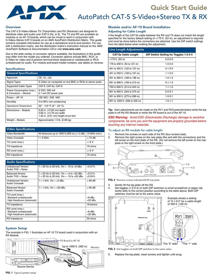
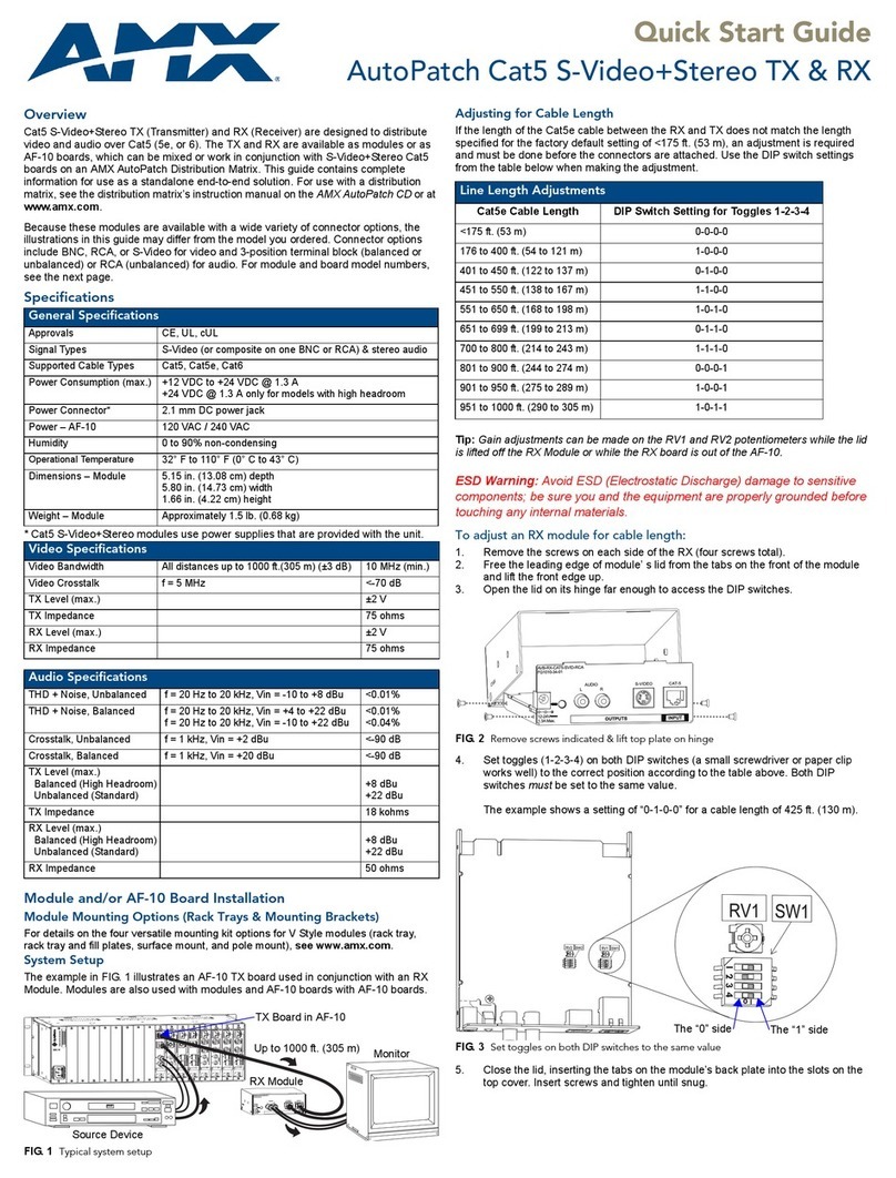
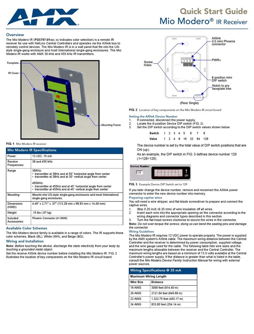
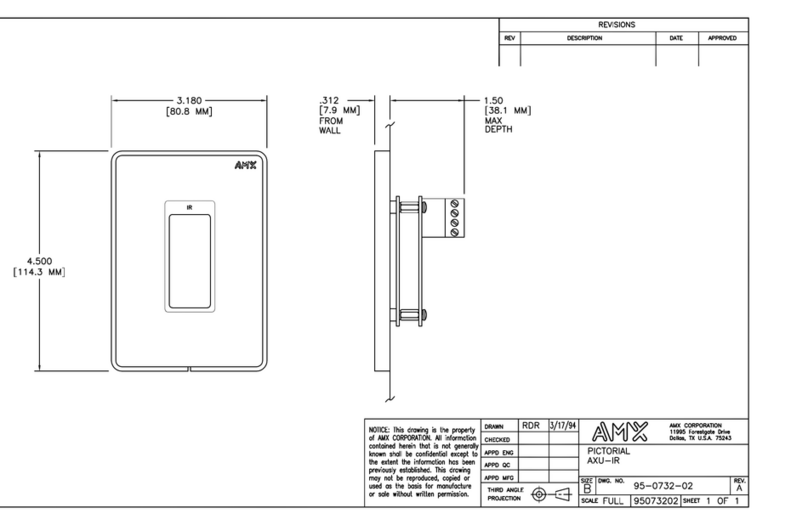
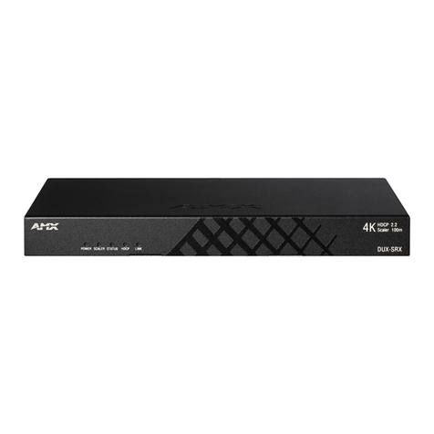
AMX DCP-SRX User manual

USER MANUAL
DCP-SRX
100m 4K HDBaseT Daisy-Chain Scaling Receiver

2USER MANUAL
DCP-SRX
TABLE OF CONTENTS
IMPORTANT SAFETY INSTRUCTIONS ...................................................................03
1. INTRODUCTION.................................................................................................04
2. PACKING LIST ...................................................................................................05
3. SPECIFICATIONS...............................................................................................06
4. PANEL OVERVIEW.............................................................................................08
4.1 Front Panel.................................................................................................08
4.2 Rear Panel..................................................................................................08
5. SCALER SWITCH...............................................................................................09
6. APPLICATION & INSTALLATION........................................................................10
6.1 Typical Application .....................................................................................10
6.2 Installation & Connection ...........................................................................10
7. CEC & RS232 AUTO CONTROL .........................................................................13
8. SET-UP & CONTROL..........................................................................................15
8.1 Web UI .......................................................................................................15
8.1.1 Log Into Web UI ...............................................................................15
8.1.2 Control Through Web UI...................................................................16
8.1.2.1 Status ....................................................................................18
8.1.2.2 Configuration.........................................................................18
8.1.2.3 Advanced...............................................................................23
8.1.2.4 Device List.............................................................................29
8.2 Telnet..........................................................................................................29
9. RESET................................................................................................................31
APPENDIX: API COMMAND SET............................................................................32

3
USER MANUAL
DCP-SRX
IMPORTANT SAFETY INSTRUCTIONS
NOTE: We reserve the right to change the content from time to time without
notice.
WARNINGS: To reduce the risk of fire, electric shock or product damage, please
observe the following Safety Instructions while installing and operating the
product:
Do not expose this apparatus
to rain, moisture, dripping or
splashing. No objects filled with
liquids, such as vases, shall be
placed on the apparatus.
To prevent risk of electric
shock or fire hazard due to
overheating, do not obstruct
the unit’s ventilation openings
with newspapers, tablecloths,
curtains, and similar items.
Do not install near any heat
sources such as radiators,
heat registers, stoves, or other
apparatus (including amplifiers)
that produce heat.
Do not place sources of naked
flames, such as lighted candles,
on the unit.
Clean this apparatus only with
dry cloth.
Protect the power cord from
being walked on or pinched
particularly at plugs.
Refer all servicing to qualified
service personnel.
Unplug this apparatus during
lightning storms or when un-
used for long periods of time.
Only use attachments/accesso-
ries specified by the manufac-
turer.
Do not install or place this
unit in a bookcase, built-in
cabinet or in another confined
space. Ensure the unit is well
ventilated.

4USER MANUAL
DCP-SRX
1. INTRODUCTION
DCP-SRX is a Scaling Receiver able to transmit 4K/Ultra HD signal over HDBaseT up to
100 meters and supports cascade connection of multiple A/V sources, displays or any
devices capable of HDBaseT transmission.
DCP-SRX accepts and outputs HDBaseT signal through its HDBT IN and HDBT OUT
ports. Its HDMI OUT supports up to 4K@60Hz scaling output and audio extraction and
can be connected to a local monitor or zone displays. With a built-in Ethernet Switch,
DCP-SRX allows Ethernet pass-through over HDBaseT for either LAN control or LAN
access.
DCP-SRX is embedded with a CEC controller and a RS232 controller, with its RS232 port
capable of RS232 serial communication over TCP/IP.
DCP-SRX is designed bearing user-friendliness in mind. For users with different levels
of A/V switching experience, DCP-SRX offers various control options, either the intuitive
Web UI or the Telnet controls for advanced users. A SCALER switch is available for
manual set-up of output scaling parameter. An extra USB connector is provided for
power charging mobile phones, tablets and the like. For applications in need of a Scaling
Receiver with great ease of control and versatility in connection, DCP-SRX is the choice.
DCP-SRX offers a future-ready Ultra HD A/V switching and distribution solution and is
ideal for collaboration or presentation in conference and education applications.
Features
• HDMI OUT with built-in scaler (up to 4K@60Hz) and audio extraction
• HDBT IN and HDBT OUT for cascade connection of multiple A/V sources and
displays
• HDMI IN with HDCP 2.2 compatibility
• Transmits 4K@60Hz 4:2:0 up to 70m over Cat5e/Cat5 or up to 100m over Cat6a/
Cat7
• Built-in CEC and RS232 controller for smart control of display devices
• Daisy-chain Grouping for setting up separate groups with a system
• Intuitive WEB UI control and Telnet control for advanced users
• Built-in Ethernet Switch for LAN control or access
• Built-in USB charger provides power of 5V/1.5A
• Advanced signal re-locking and cable equalization for multiple daisy-chains
• Audio supports PCM 2 channels

5
USER MANUAL
DCP-SRX
2. PACKING LIST
1 x DCP-SRX
1 x Power Supply (12 DVC, 3A)
2 x Phoenix Male Connectors (3.5 mm, 3 pins)
2 x Mounting Brackets
1 x User Manual (this manual)

6USER MANUAL
DCP-SRX
3. SPECIFICATIONS
Technical
Input Connections 1 x HDBaseT IN
Input Video Type HDBaseT
Input Resolution
• VESA
800 x 6008, 1024 x 7688, 1280 x 7688, 1280 x 8008, 1280 x 9608,
1280 x 10248, 1360 x 7688, 1366 x 7688, 1400 x 10508,1440 x 9008,
1600 x 9008, 1600 x 12008, 1680 x 10508, 1920 x 12008.
• SMPTE
720 x 480P7,8,720 x 576P8,1280 x 720P6,8,1920 x 1080I6,8,1920 x
1080P2,3,5,6,8,3840 x 2160P2,3,5,6,8, 4096 x 2160P2,3,5,6,8.
Note:
1. 1 = @ 23.98 Hz, 2 = @ 24 Hz, 3 = @ 25 Hz, 4 = @ 29.97 Hz, 5
= @ 30 Hz, 6 = @ 50 Hz, 7 = @ 59.94 Hz, 8 = @ 60 Hz;
2. HDMI 1.4 with 4k@50Hz/60Hz(chroma sub-sampling 4:2:0
8-bit only) for HDBaseT input.
Output 1 x HDMI OUT, 1 x HDBaseT OUT
Output Signal Type HDMI 2.0 with 4K, HDBaseT
Output Resolution
• HDMI
3840 x 2160P5,8,1920 x 12008,1920 x 1080P8,1280 x 10248, 1280 x
8008, 1280 x 720P8, 1024 x 7688, Auto Scaler.
• HDBaseT
1) VESA
800 x 6008, 1024 x 7688, 1280 x 7688, 1280 x 8008, 1280 x 9608,
1280 x 10248, 1360 x 7688, 1366 x 7688, 1400 x 10508,1440 x 9008,
1600 x 9008, 1600 x 12008, 1680 x 10508, 1920 x 12008.
2) SMPTE
720 x 480P7,8, 720 x 576P8,1280 x 720P6,8, 1920 x 1080I6,8, 1920 x
1080P2,3,5,6,8, 3840 x 2160P2,3,5,6,8, 4096 x 2160P2,3,5,6,8.
Note:
1. 1 = @ 23.98 Hz, 2 = @ 24 Hz, 3 = @ 25 Hz, 4 = @ 29.97 Hz, 5
= @ 30 Hz, 6 = @ 50 Hz, 7 = @ 59.94 Hz, 8 = @ 60 Hz;
2. HDMI 1.4 with 4k@50Hz/60Hz( chroma sub-sampling 4:2:0
8-bit only) for HDBaseT input.

7
USER MANUAL
DCP-SRX
Control
Control Methods Telnet, Web UI
General
Operating Temperature
& RH 32°F ~ 113°F (0°C ~ 45°C), 10% ~ 90% (non-condensing)
Storage Temperature &
RH -4°F ~ 158°F (-20°C ~ 70°C), 10% ~ 90% (non-condensing)
ESD Protection
Human-body model:
• ±8kV (air-gap discharge)
• ±4kV (contact discharge)
Power Supply 12 VDC, 3A
Power Consumption 20.6 W (Maximum)
Dimensions (W x H x D) 223 mm x 27 mm x 196.2 mm
Weight 1.2 kg
Certification CE, FCC

8USER MANUAL
DCP-SRX
4. PANEL OVERVIEW
4.1 Front Panel
1 2 3
Item Name Description
1 ID LED
Indicates the device to be controlled. The LED will flash
when the ID button in the Web UI (Configure > Device) is
turned ON.
2 POWER LED Illuminates when the device is powered on.
3 USB connector Accepts a flash driver for Scaler updating.
4.2 Rear Panel
1 2 3 45 6 7 8 9
Item Name Description
1 HDBT IN Connect to HDBT OUT of any HDBT transmitter or DCP-MTX
or another DCP-SRX.
2 RS232 Connects to a controllable device, e.g. projector, for RS232
pass-through control.
3 ETHERNET Connects to a LAN device, e.g. IP-based touch panel for LAN
control.
4 HDMI OUT Connects to an HDMI display device.
5 AUDIO OUT Connects to an audio system, e.g. amplifier.
6 SCALER switch Uses a DIP switch for adjust output scaling.
7 HDBT OUT Connects to HDBT IN of any HDBT device or DCP-MTX.
8 RESET button Resets the device to factory default.
9 DC 12V Connects to the power adapter provided.

9
USER MANUAL
DCP-SRX
5. SCALER SWITCH
DCP-SRX installs a “SCALER” DIP switch at the rear panel for manual adjustment of
the scaling output.
By default, the SCALER switch is in “Auto Scaler” position (all switches are set to 0000
or upward). Users are allowed to set DCP-SRX to desired scaling output resolution by
using the SCALER switch.
0
11 2
ON DIP
3 4
Default:
Auto Scaler
DIP SWITCH SETTINGS SCALING OUTPUT RESOLUTION
0 0 0 0 Auto Scaler (Default)
0 0 0 1 Fix 1024 x 768@60Hz
0 0 1 0 Fix 1280 x 720@60Hz
0 0 1 1 Fix 1280 x 800@60Hz
0 1 0 0 Fix 1280 x 1024@60Hz
0 1 0 1 Fix 1920 x 1080@60Hz
0 1 1 0 Fix 1920 x 1200@60Hz
0 1 1 1 Fix 3840 x 2160@30Hz
1 0 0 0 Fix 3840 x 2160@60Hz
1 0 0 1 SCALER by WEB GUI or API control
Other settings Reserved for future use

10 USER MANUAL
DCP-SRX
6. APPLICATION & INSTALLATION
6.1 Typical Application
DCP-SRX is normally used with DCP-MTX 4K HDBaseT Daisy-Chain Presentation
Switcher and supports cascade connection of multiple DCP-SRXs and DCP devices.
To install multiple DCP-MTXs and DCP-SRXs, simply connecting HDBT OUT of DCP-
MTX/DCP-SRX to HDBT IN of next DCP-MTX/DCP-SRX, you will get a Chain Mode
connection. By connecting the last DCP device back to the first through HDBT, you will
get a Ring Mode system. (see application example below).
DCP-MTX 1 DCP-MTX 2 DCP-SRX 1 DCP-SRX 2
SOURCE 1 SOURCE 2
DCP-MTX N
SOURCE N
DISPLAY 1 DISPLAY 2
HDBaseT HDBaseT HDBaseT HDBaseT
DCP-SRX N
DISPLAY N
HDBaseT
Chain Mode
DCP-MTX 1 DCP-MTX 2 DCP-SRX 1 DCP-SRX 2
SOURCE 1 SOURCE 2
DCP-MTX N
SOURCE N
DISPLAY 1 DISPLAY 2
HDBaseT HDBaseT HDBaseT
HDBaseT
HDBaseT
DCP-SRX N
DISPLAY N
HDBaseT
Ring Mode
6.2 Installation & Connection
To create a Chain- or Ring-type connection of multiple DCP-MTXs, DCP-SRXs, sources
and displays, please refer to the instructions below and the “SYSTEM WIRING” chart:
1. Connect DCP-MTXs and DCP-SRXs through HDBT:
1) Connect HDBT OUT of the first DCP-MTX to HDBT IN of the next (e.g. DCP-
MTX 1 to DCP-MTX 2);
2) Connect the rest DCP-MTXs through HDBT likewise.
3) Connect HDBT OUT of the first DCP-SRX to HDBT IN of the next (e.g. DCP-
SRX 1 to DCP-SRX 2);
4) Connect the rest DCP-SRXs through HDBT likewise.
5) Connect HDBT OUT of the last DCP-MTX to HDBT IN of the first DCP-SRX

11
USER MANUAL
DCP-SRX
(e.g. DCP-MTX N to DCP-SRX 1).
6) If Ring Mode connection is required, connect HDBT OUT of the last DCP-SRX
to HDBT IN of the first DCP-MTX (e.g. DCP-SRX N to DCP-MTX 1).
2. Set up IP Sequencing for all the DCP-MTXs and DCP-SRXs.
• Option A: Using the MYTURN button of the first DCP-MTX (e.g. DCP-MTX 1)
a) Long press the MYTURN button of DCP-MTX 1 for 10 seconds;
b) The input LEDs (HDMI IN, DP IN and VGA IN) will flash twice, then
DCP-MTX 1 will start IP sequencing automatically and the rest DCP-
MTXs and DCP-SRXs will get its individual IP address according to
their sequence in the connection loop (for instance, if DCP-MTX 1 gets
192.168.1.121 (Default IP address of DCP-MTXs), then DCP-MTX 2 will
get 192.168.1.122.)
• Option B: Using Start Sequence button on Web UI.
a) Connect your PC to ETHERNET port of the first DCP-MTX (e.g. DCP-MTX
1).
b) Login Web UI through a web browser (Default IP address of DCP-MTXs
is192.168.1.121).
c) Go to Configuration > Device > Daisy-chain Sequence. Select Daisy-chain
quantity and click “Start Sequence” to allocate IP addressing to each DCP
device.
3. Connect source and display devices to DCP-MTXs.
4. Connect an HDMI display device to HDMI OUT of each DCP-SRX. If audio output is
required, connect an audio system to AUDIO OUT of DCP-SRX.
NOTE:
• Default IP address of DCP-SRX is 192.168.1.122, DCP-MTX is 192.168.121.
• The PC used to login Web UI of DCP should be set in the same network segment
as DCP devices, e.g. 192.168.1.x.
• To avoid IP addressing conflicts, please repeat Step 2 if any DCP-MTX or DCP-SRX
is reset, removed from and added to the connection.
• To make CEC control effective, please use CEC-enabled display devices.
• Quality CAT cables, e.g. Cat6, AWG23 or S/FTP cable, are highly recommended.
For more information about HDBaseT transmission cables, please visit: www.
hdbaset.org/cable.

12 USER MANUAL
DCP-SRX
DCP-MTX 1
HDMI
LAPTOP
VGA AUDIO
LAPTOP
DP
LAPTOP
HDMI
MONITOR
ETHERNET
TOUCH PANEL
IO
KEY PAD
DCP-MTX 2
HDMI
LAPTOP
VGA AUDIO
LAPTOP
DP
LAPTOP
HDMI
MONITOR
ETHERNET
TOUCH PANEL
IO
KEY PAD
DCP-MTX 3
HDMI
LAPTOP
VGA AUDIO
LAPTOP
DP
LAPTOP
HDMI
MONITOR
ETHERNET
TOUCH PANEL
IO
KEY PAD
DCP-MTX N
HDMI
LAPTOP
VGA AUDIO
LAPTOP
DP
LAPTOP
HDMI
MONITOR
ETHERNET
TOUCH PANEL
IO
KEY PAD
HDBT HDBT HDBT
SYSTEM WIRING
DCP-SRX 1
ETHERNET
ETHERNET
HDMI AUDIORS232
PROJECTOR AUDIO SYSTEM
ETHERNET SWITCH
PC
WEB UI
CONTROLLER (E.G. NX-2200)
ETHERNET
DCP-SRX 2
HDMI AUDIORS232
PROJECTOR AUDIO SYSTEM
DCP-SRX N
HDMI AUDIORS232
PROJECTOR AUDIO SYSTEM
HDBT HDBT
HDBT
1. DCP-SRX should be used with DCP-MTX.
2. To create a Ring-type connection, connect the
last device (DCP-SRX N) to the first (DCP-MTX
1) through HDBT.
HDBT

13
USER MANUAL
DCP-SRX
7. CEC & RS232 AUTO CONTROL
DCP-SRX is embedded with a CEC controller and a RS232 controller. When CEC /
RS232 Auto Control is switched on, DCP-SRX will detect the signal status and send
CEC / RS232 command to power on or off the display connected. CEC / RS232
Auto Control of DCP-SRX can be configured through Web UI or Telnet. For more
information, please refer to “8.1 WEB UI” and “8.2 TELNET“.
When CEC / RS232 Auto Control is enabled,
• DCP-SRX will automatically detect the status of signal from HDBaseT IN.
• DCP-SRX will power on the display (see flow chart below):
1) If active input signal is present, DCP-SRX will send a CEC/RS232 command to
power on the display connected to HDMI OUT/RS232 port immediately.
Detect for active input signal
(HDBT)
1
DCP-SRX
Display
HDBaseT HDBaseT
DCP-SRX
Display
HDBaseT HDBaseT
Power on the display immediately
when active signal is detected
2
HDBT
• DCP-SRX will power off the display (see flow chart below):
1) If no input signal is present, DCP-SRX will send a CEC/RS232 command to
the display connected to HDMI OUT/RS232 port and start to countdown the
Delay Time till the display shuts down.
2) If any active input signal is inserted in the middle of countdown, the
countdown will cancel automatically.

14 USER MANUAL
DCP-SRX
Detect for active input signal
(HDBT)
1
Start to countdown if
no active input signal
is detected
2
Cancel countdown
4
When active input signal
is inserted
3
The display connected
will shutdown
3
DCP-SRX
Display
HDBaseT HDBaseT
Display
DCP-SRX
HDBaseT HDBaseT
30
30
Display
DCP-SRX
HDBaseT HDBaseT
0
NOTE:
• To realize CEC/RS232 Auto Control of DCP-SRX, please connect a display device
which accepts CEC/RS232 command.

15
USER MANUAL
DCP-SRX
8. SET-UP & CONTROL
DCP-SRX is designed with ease of connection and control in mind. When the device
is connected and powered on, you can choose the optimal way to control the unit at
your convenience, either through the specifically designed web-based user interface or
Telnet.
8.1 WEB UI
DCP Series comes with a tailor-designed web-based user interface (or Web UI in
short) which allows you to set up basic controls or advanced settings of a DCP device,
including DCP-SRX or a DCP system with great ease and convenience.
The Web UI can be accessed through a modern browser, e.g. Chrome, Safari, Firefox,
etc.
DCP-SRX ships with a default IP address of 192.168.1.122 and default login password
for Wen UI of admin.
8.1.1 Log Into WEB UI
To get accessed to Web UI of DCP-SRX, please follow the instructions below.
1. Connect your PC to ETHERNET port of DCP-SRX through a Catx Cable.
2. Set your PC to the same network segment as DCP-SRX, e.g. 192.168.1.xxx.
3. Enter DCP-SRX's IP address (default: 192.168.1.122) in your browser and press
to enter.
4. Enter login password (default: admin) in the login window, choose the language
you wish to use, then press “Login”.
5. The following main page will appear when you successfully log in.

16 USER MANUAL
DCP-SRX
TIP:
In case you forget the IP address or the login password newly changed for DCP-SRX,
please reset the device using the “RESET” button. For more information, please go to
“9. RESET”.
8.1.2 Control through WEB UI
Web UI of DCP-SRX is comprised by four sections: Status, Configuration, Advanced,
and Device List.
The following menu tree shows the function structure of the Web UI, which is followed
by detailed introduction to each section.

17
USER MANUAL
DCP-SRX
Configuration
Device
Device Name
ID (ON/OFF)
Device Name
Daisy-chain Grouping
Network
Video
Audio
Daisy-chain Grouping (ON/OFF)
IP Mode (Static/DHCP)
IP Address (default: 192.168.1.122)
Netmask (default: 255.255.255.0)
Gateway (default: 192.168.1.1)
Volume
Scaling output setting
Mute (ON/OFF)
Video & Audio
Control
CEC Controller
CEC Auto-Control (ON/OFF)
Delay Time
CEC Manual Control (Display off /on)
RS232 Controller
Baud Rate
Parity Bits
Data Bits
Stop Bits
Hex String (ON/OFF)
End Flag
RS232 Auto-Control
Delay Time
RS232 Wakeup Command
RS232 Standby Command
RS232 Manual Control (Display off/on)
RS232 Pass-Through
Baud Rate
Parity Bits
Data Bits
Stop Bits
Hex String (ON/OFF)
End Flag
Command
System
Automatic Logout
Firmware
(MCU & ARM & Scaler)
Factory Default
Reboot
Enable (ON/OFF)
Delay Time
Welcome Menu
Custom Web UI Logo
Change Password
System
Firmware
Advanced
Device 1 (Name, IP)
Device 2 (Name, IP)
Device n (Name, IP)
Device List ...
Status
Device 1 (Name, IP, Sequence, Grouping, Signal)
Device 2 (Name, IP, Sequence, Grouping, Signal)
Device n (Name, IP, Sequence, Grouping, Signal)
...

18 USER MANUAL
DCP-SRX
8.1.2.1 Status
The Status section shows the current status of DCP-SRX and/or other DCP devices
connected. Each DCP device, including DCP-SRX, uses different gradient colors to
indicate its status.
• Yellow gradient: The DCP device is working in ID Mode (ID button under
“Configuration > Device” is turned on, and its ID LED flashes).
• Green gradient: The DCP device is successfully connected but not in ID Mode.
• Red gradient: The DCP device is not connected.
Moving your mouse up onto a DCP device, informaiton of the device will be displayed
in a pop-up window. DCP-SRX will show such informaiton as Name, IP Address,
Sequence, Grouping.
8.1.2.2 Configuration
The Configuration section includes Device, Video & Audio and Control and allows you
to set up the DCP-SRX, input source signal and control methods.
Device
The Device sub-menu is used to perform the following functions:
• ID
• Device Name
• Daisy-Chain Grouping
• Network
1) ID
The ID button is used to help located the DCP-SRX in a DCP connection system.

19
USER MANUAL
DCP-SRX
Click to turn ON the ID button, then check the ID LED of each DCP-SRX or DCP device.
The device with a flashing ID LED is the one accessed through Web UI.
2) Device Name
The Device Name allows you to redefine the name of DCP-SRX or a DCP device in case
multiple DCP devices are connected.
NOTE:
The Device Name must be 1-20 characters in length and can include English letters,
Chinese characters, numbers, space, “_” or “-”.
3) Daisy-Chain Grouping
The Daisy-Chain Grouping section is for you to create small groups and is realized by
switching on the Daisy Chain Grouping button and stopping signal from transmitting to
downstream DCP devices.
Example:
To create Group A (include DCP-MTX 1-2 & DCP-SRX 1) and Group B (include DCP-
MTX 4 & DCP-SRX 2) in a Ring Mode connection as below.
DCP-SRX z
DCP-MTX 1 DCP-MTX 2 DCP-MTX 3 DCP-MTX 4DCP-SRX 1 DCP-SRX 2
Group A Group B
Group A: Switch on Daisy-Chain Grouping button of both DCP-SRX z & DCP-SRX 1.
Group B: Switch on Daisy Chain Grouping button of both DCP-MTX 3 & DCP-SRX 2.

20 USER MANUAL
DCP-SRX
4) Network
The Network section allows you to set up the IP mode of the DCP-SRX to either Static
or DHCP.
By default, DCP-SRX is shipping in Static mode, with default IP address of
192.168.1.122, Netmask of 255.255.0.0 and Gateway of 192.168.1.1.
You are free to change the network setting when multiple devices are connected to
avoid IP conflicts.
NOTE:
The DCP device will automatically reboot after the network setting is changed.
Video & Audio
The Video & Audio sub-menu is used to perform the following functions:
• Scaling Output Setting
• Volume & Mute
1) Scaling Output Setting
The Scaling Output Setting button is used to adjust output resolution of DCP-SRX. By
default, the Scaling Output Setting of DCP-SRX is in Auto Scaler mode (the SCALER
DIP switch is set to 0 0 0 0).
To adjust Scaling Output Setting of DCP-SRX through Web UI, please manually set the
SCALER switch on the rear panel to 1 0 0 1.
Table of contents
Other AMX Receiver manuals

AMX
AMX Endeleo Multi-Format Receiver UDM-RX01 User manual

AMX
AMX AXR-RF User manual

AMX
AMX AXD-IR Plus User manual

AMX
AMX Mio Moderno MIO-IRRX User manual

AMX
AMX PMB-IRI User manual

AMX
AMX AXU-IR User manual

AMX
AMX MX8 User manual

AMX
AMX AXD-IR Plus User manual

AMX
AMX AutoPatch Cat5 S-Video+Stereo TX User manual
AMX
AMX AXC-RCVI User manual

Popular Receiver manuals by other brands

Bosch
Bosch LR 1 Professional Original instructions

Qviart
Qviart LUNIX3 4K user manual

Sony
Sony STR-DA2000ES - Fm Stereo/fm-am Receiver operating instructions

FRIEDHELM LOH
FRIEDHELM LOH Rittal RiLine Compact SV 9635.200 Assembly and operating instructions

Albrecht
Albrecht DR 70 user manual

Atlas
Atlas RX-110 Installation and operation manual