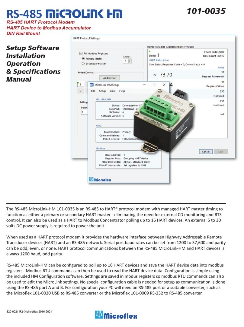
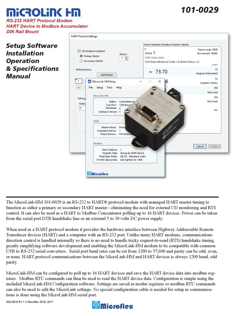
Microflex Microlink-HM+ Owner's manual

Installation
Operation
Specifications
620-0034 R1 © Microflex 2016-2020
101-0097
MicroLinK HM+
HART Protocol Modem
HART to Modbus Accumulator
USB, RS-485 or RS-232 Communications Port
DIN Rail Mount

Safety Consideraons............................................................................................................................................ 1
Overview............................................................................................................................................................... 2
Configuraon ........................................................................................................................................................ 2
Block Diagram ....................................................................................................................................................... 3
Mounng .............................................................................................................................................................. 4
Power Supply ........................................................................................................................................................ 4
Connecng to a HART Loop .................................................................................................................................. 4
Serial Port.............................................................................................................................................................. 5
USB Port ................................................................................................................................................................ 5
USB Drivers ....................................................................................................................................................... 5
Modbus Registers.................................................................................................................................................. 6
Specificaons ........................................................................................................................................................ 7
Warranty ............................................................................................................................................................... 9
Table of Contents
• Read and understand this manual before starƟng the configuraƟon and installaƟon.
• InstallaƟon and wiring should be performed by a professional to meet all facility, local, and state
requirements and regulaƟons.
Safety Considerations
Conformity in accordance with Part 2, and Part 15, Subparts A and B of
the Federal Communications Rules and Regulations, and ICES-003 of the
Industry Canada standards.
This device complies with part 15 of the FCC rules. Operation is subject to
the following two conditions: (1) This device may not cause harmful interfer-
ence, and (2) this device must accept any interference received, including
interference that may cause undesired operation. Changes or modifications
not expressly approved by Microflex could void the user’s authority to oper-
ate this equipment.
Emissions EN55022: 1998
Electrostatic Discharge EN61000-4-2: 1995, A1: 1998, A2: 2001
Radiated Immunity EN 61000-4-3: 2002
Safety Compliance EN 60950-1: 2002
This device is not intended for connection to the phone line through the
appropriate converters and shall not be connected to telecommunication
lines because it has no protection against over-voltages which may exist in
these lines.
The user shall ensure the protection of the operator from access to areas
with hazardous voltages or hazardous energy in their equipment.
The user shall ensure that the connection port of the field device and the
modem is separated at least by basic insulation from any primary circuit
existing in the field device.
1

Overview
MicroLink-HM+ is a HART®protocol modem to USB/RS-485/RS-232 serial interface. In addion to funconing as a HART
protocol modem, it can also be configured to connuously poll HART devices, filling modbus registers with device values
without any addional HART soware. Modbus registers can then be read using modbus-RTU command 3 from the USB
and/or RS-485/RS-232 serial ports.
As a HART protocol modem the serial port is typically set to 1200 baud, odd parity. Most HART soware will require
these sengs. It is possible to set the serial port to other baud rates and parity sengs. In this case MicroLink-HM will
receive the HART command at the higher baud rate then transmit the HART data at 1200 baud, odd parity onto the
HART loop. The 1200 baud, odd parity HART reply packet is received by the MicroLink-HM modem and then transmied
back at the higher baud rate.
MicroLink-HM+ ships configured to operate as a HART protocol modem compable with most HART configuraon
and test soware. Included on the CD is the PACTware FDT frame, HART Protocol DTM, and Microflex Generic DTM
soware. For informaon on installing PACTware and the DTM, please reference the PACTware Quick Start Guide. Serial
communicaons to the HART modem can be USB, RS-485, or RS-232. The serial port is set for RS-485 protocol, 1200
baud, odd parity by default. Use the HM Configurator app, included on the CD, to change the port sengs.
If Fill Modbus Registers mode is enabled, MicroLink-HM will funcon as a HART master (primary or secondary) conn-
uously polling devices and storing variable values into registers. No addional HART soware is needed. The HART loop
may contain a single device or up to 16 devices. When more than one device is in the loop each HART device must have
a unique HART polling address. The address for each device is set separately before wiring the device into the mul-
drop loop. The HART Device Addresser soware applicaon, installed with the HM Configurator app, can be used to
assign addresses to HART devices.
Modbus-RTU command 3 is used to read the registers from the MicroLink-HM modbus slave. Variable data can be read
as 16 bit integers or 32 bit floang point. Up to 4 variables plus loop current for each polled HART device is available.
If configured to Fill Modbus Registers and a HART packet is received on the USB or RS-485/RS-232 port MicroLink-HM
will temporarily switch to HART modem mode and pause polling devices. A packet type is idenfied by monitoring the
first byte received in a new packet. HART protocol packets always begin with a hex FF preamble character and modbus
packets begin with the slave address. If no HART commands are received over the serial port for 60 seconds, or if a
modbus slave address is received, MicroLink-HM will exit HART modem mode and resume polling and filling modbus
registers.
Modbus port type, slave address, baud rate, parity, and other sengs are set using the HM Configurator app soware.
MicroLink-HM Configuration
Configuraon changes are done using the included HM Configurator app. The app can be connected to the MicroLink-
HM+ USB port or to the RS-485/RS-232 serial port. The serial port was set at the factory to RS-485 mode. To change the
serial port to RS-232 mode you must connect using the USB port first.
The USB port can supply power to the MicroLink-HM. This allows you to make configuraon changes without
connecng an external power supply.
Refer to the HM Configurator App manual for details on installing and using the configuraon soware.
2

Power
Supply
RS-485/RS-232
Transceiver
HART
Modem
Microcontroller
Modbus Register
Tables
TX
RX
CD
RTS
1 - DC (+)
2 - DC (-)
3 - GND
4 - TX B
5 - RX A
5-Pin
Terminal Block
HART Loop
Terminals
HART LED
COM LED
USB
MicroLink-HM+ Block Diagram
HART Loop Screw Terminals
USB Port
HART Transmit/Receive LED
DIN Rail Release
Serial Port Transmit/Receive LED
+/- DC Power 5-30VDC
G Serial Port Common
B/A RS-485 Port
TX/RX RS-232 Port
3

Address 0
LOOP
POWER
SUPPLY 250Ω
Address 1
HART
DEVICE
Address 2
HART
DEVICE
Address 15
HART
DEVICE
LOOP
POWER
SUPPLY
HART
DEVICE
250Ω
Figure 1. Connecting HART modem to device loop.
HART Loop with One Device
HART Multi-Drop Loop
Connect the two screw terminals to the HART device
or HART loop. Microlink provides electrical isolaon
between the HART loop and the serial port so it is safe
to ignore grounding and polarity issues when making
the HART connecons. Figure 1 shows one device and
mul-drop HART loop connecons.
The HART protocol requires a loop resistance of
230 to 600 ohms, typically 250 ohms.
Refer to your equipment installaon instrucons for
details on connecng a HART master or configuraon
device to the loop.
Mounting
The DIN rail mounting clip is compatible with widely used 35mm EN 50022 rails. It can be snap mounted and removed
from the mounting rail without tools for quick installation and servicing.
Power Supply
MicroLink-HM+ requires an external 5 to 30 volt DC power supply.
Posive side to Pin 1, and negave side to Pin 2 on the 5-pin screw terminal block.
Maximum supply current ranges from 5mA at 30 volts to 25mA at 5 volts.
In most cases the transmier loop power supply can be used to power MicroLink-HM, eliminang the need for a
dedicated MicroLink-HM supply.
Power can also be supplied by an acve enumerated USB port, making configuraon possible with only a USB
connecon. MicroLink-HM+ can funcon as a USB to HART protocol modem without the need for an external power
supply.
Connecting to a HART Loop
4

USB Port
The USB port can be used for device configuraon, monitoring, or as a USB to HART protocol modem. MicroLink-HM
can disnguish between HART and modbus packets. When a HART protocol packet is received on USB it will be routed
directly to the HART modem and transmied onto the HART loop. If MicroLInk-HM is polling devices the polling process
will be disabled while the HART command is being processed. Polling will be re-enabled aer 60 seconds of no HART
packet acvity on the USB port or if a modbus packet is received on the USB port.
USB Drivers
USB drivers create a virtual serial COM port that appears as a serial port to your applicaon soware. If your PC is
connected to the Internet the drivers will be automacally downloaded and installed when the HM modem is first
connected to a USB port. The drivers can also be installed before connecng to the USB port by running
file CDM21228_Setup.exe from the included CD. To download drivers got to www.microflx.com/pages/drivers.
The USB virtual serial port operates at 1200 baud and odd parity, slave ID 250, and uses standard modbus commands to
read and write registers.
Use the Windows Device Manager to determine the assigned Com port number. It will be listed under
Ports (COM & LPT) while the cable is aached to the MicroLink-HM+ USB port.
Serial Port
The serial port can be configured for RS-485 or RS-232 protocol using the HM Configurator app soware or by wring to
modbus register 775. The factory default is RS-485 mode, 1200 baud odd parity.
RS-485 Serial Protocol
An RS-485 bus can consists of mulple RS-485 devices connected in parallel to a bus cable. To eliminate line reflecons,
each cable end should be terminated with a terminaon resistor whose value matches the characterisc impedance
of the cable. This method, known as parallel terminaon, allows for higher data rates over a longer cable length.
MicroLink-HM+ does not include internal RS-485 terminaon internally.
• Connect terminal G to the RS-485 bus shield or ground wire. Internally connected to Supply (-) or ground
• Connect terminal B to the RS-485 bus B or (+)
• Connect terminal A to the RS-485 bus A or (-)
MicroLink-HM does not provide isolaon between the RS-485 port and power supply ground.
The G terminal is internally connected to the power supply (-) terminal.
RS-232 Serial Protocol
By default the serial port is set to RS-485 protocol. Connect HM Configurator app soware to the MicroLink-HM USB port to change
the serial port to RS-232 mode using the Setup -> Modbus dialog.
Figure 2 shows typical wiring connecons to connect to a 9-Pin RS-232 connector. Only transmit, receive, and ground are used.
5 GND
2 RX
3 TX
+
G
TX
RX
5V to 30V
DC SUPPLY
MicroLink-HM+ HART
Loop
ĺ
ĸ
RS-232
Serial Port
DB-9 Female
Figure 2. Connecting to DB-9 RS-232 9-Pin serial port.
5

Modbus Registers
Register locaons and details can be found in the HM Configurator soware manual. The manual is included on the CD
and can be downloaded from www.microflx.com.
Write Locking
Wring to registers can be locked or write-protected aer seng the configuraon to prevent unwanted changes to the
configuraon. Refer to the HM Configurator soware manual for details on write locking and unlocking registers.
Polled HART Devices Long Address Table, 700 - 747
Device ID informaon is read from each polled device using the devices polling address and HART command 0. The
reply to command 0 for each polled device is used to populate the long address table. When MicroLink-HM needs to
poll for the device variables, using HART command 3, this table holds the informaon needed to build the 5-byte long
address. Table values can be read using modbus-RTU command 3. Only the polled devices you have configured will
contain valid informaon. The table is updated when the device address is unknown or a bad HART reply was received.
HART Device Polling Address Table, 748 - 755
The polling address for each polled device is stored in this table. Two polling addresses in each 16 bit register. If ad-
dress 0 is used then only one device can be polled and Device 1 should be set to 0. Address 0 is not valid in mul-drop
systems. For HART devices with HART revision 3 through 5 you should use polling addresses 1 - 15. Addresses 16-63
require HART revision 6 or higher.
Number of Decimal Places Table, 756 - 771
When storing the HART variable data in 16-bit modbus registers the maximum range is -32768 to 32767. To increase the
possible resoluon, the variable value read from the HART device is decimal posion adjusted before being saved in the
16-bit register. When the register is read, the value must be corrected by the number of decimal places to produce the
correct value. The number of decimal places for each variable occupies 4-bits in the register with one register for each
polled device.
Setup Registers, 772 - 777
The MicroLink-HM configuraon can be changed using the HM Configurator App or by wring to modbus registers using
modbus-RTU commands 6 or 16. Command 6 writes to a single register and command 16 writes to a range of modbus
registers. The configuraon register values are saved in nonvolale memory and are not lost when MicroLink-HM power
is removed.
6

Specifications
Power
Supply Range..................................................................................................................................5 to 30 Volts DC
Max Operang Current .................................................................................................... 25mA @ 5V, 5mA @30V
Typical Operang Current ......................................................................................... 8.8mA @ 12V, 5.2mA @ 24V
Field Connections
Terminaon................................................................................................ Pluggable Screw Terminal, 26-16 AWG
+ Power Supply (+) ......................................................................................................................................... Pin 1
- Power Supply (-).......................................................................................................................................... Pin 2
G Serial Port Ground Internally connected to Supply (-)................................................................................. Pin 3
TX B RS-485 (+), RS-232 Transmit ................................................................................................................... Pin 4
RX A RS-485 (-), RS-232 Receive ..................................................................................................................... Pin 5
HART Modem
Terminaon...............................................................................................Pluggable Screw Terminals, 26-12 AWG
Connecon Method ............................................................................... Transformer Isolated, Capacitor Coupled
Loop Isolaon..................................................................................... 3000Vrms 1 min Pri-Sec Dielectric Strength
DC Loop Voltage.................................................................................................................................... 50Vdc Max
Demodulaon Jier ................................................................................................................. 12% of 1 bit Typical
Carrier Detect Threshold..................................................................................................................100mV Typical
Leakage to Process Loop .......................................................................................................................±10μA Max
Serial Port
Baud Rates .........................................................................1200, 2400, 4800, 9600, 14400, 19200, 39400, 57600
Parity............................................................................................................................................ None, Odd, Even
Protocol................................................................................................. HART or Modbus-RTU, Commands 3,6,16
Floang point byte order ............................................................................................ AD-CD or CD-AB (swapped)
Number of polled HART devices ..................................................................................................................1 to 16
Variables per polled HART device .................................................................................................(4) PV, SV, TV, FV
Supported Modbus-RTU Commands .......................................................................................................... 3, 6, 16
Surge Protecon.................................................................................................. 600W Silicone Avalanche Diodes
±15kV (HBM) ESD Protected Bus (RS-232 or RS-485)
RS-485 Mode
Driver Output Voltage................................................................................. 2V Min Unloaded, 1.5V Min RL = 50Ω
ΔInput Threshold Receive Voltage ............................................................................................................ +/- 0.2V
Receiver Input Hysteresis....................................................................................................................... 35 mV Typ
Receiver Input Current....................................................................................................................... +/- 1mA Max
Does not include RS-485 terminaon resistor
• Auto transmit control
• Power Up/Down glitch-free permits live inseron or removal
• Common mode range permits +/-7V ground difference
RS-232 Mode
Receiver Input Voltage Range ...................................................................................................................... +/-25V
Receiver Input Threshold ............................................................................................................VIL 1.1V, VIH 1.6V
Receiver Input Hysteresis...............................................................................................................................35mV
Transmier Output ..................................................................................................................................+/-5V Typ
USB
Connector ..................................................................................................................................................... USB-B
Type & Sengs ..................................................................................... FTDI Virtual Com Port, 1200 Baud, 8, O, 1
Protocol...................................................................HART or Modbus-RTU, Slave address 250, Commands 3,6,16
HART LED
Green ........................................................................................................................ HART Modem is transming
Red ................................................................................................................................. HART modem is receiving
COM LED
Green ............................................................................................................................. Serial Port is Transming
Red ......................................................................................................................................Serial Port is Receiving
7

Default Settings
Serial Port.........................................................................................RS-485 Mode, 1200 Baud, Odd Parity, 1 Stop
Modbus Address ................................................................................................................................................... 1
Fill Modbus Registers ..............................................................................Disabled (HART Protocol Modem Mode)
Poll Interval .............................................................................................................................................2 Seconds
Environmental
Operang Temperature............................................................................................-30°C to 60°C (-22°F to 140°F)
Storage Temperature ...............................................................................................-40°C to 85°C (-40°F to 185°F)
Humidity ......................................................................................................................0 to 95% (non-condensing)
Enclosure
Polycarbonate plasc with Stainless Steel Cover
Weight....................................................................................................................................................2.3 ounces
Mounng ................................................................................................................................. 35mm DIN Rail Clip
8
2.45
62.3 mm
3.32
84.2 mm
1.58
40.1 mm
1.03
26.2 mm
.42
10.6 mm
1.66
42.2 mm
SN: 123456

Limited Warranty
Microflex, LLC warrants this unit against defects in materials and workmanship for a
period of one year from the date of shipment. Microflex, LLC will, at its option, repair or
replace equipment that proves to be defective during the warranty period. This warranty
includes parts and labor.
A Return Materials Authorization (RMA) number must be obtained from the factory
and clearly marked on the outside of the package before equipment will be accepted for
warranty work.
Microflex, LLC believes that the information in this manual is accurate. In the event that
a typographical or technical error exist, Microflex, LLC reserves the right to make changes
without prior notice to holders of this edition. The reader should consult Microflex, LLC
if any errors are suspected. In no event should Microflex, LLC be liable for any damages
arising out of or related to this document or the information contained in it.
EXCEPTAS SPECIFIED HEREIN, MICROFLEX, LLC MAKES NO WARRANTIES OR
MERCHANTABILITY OR FITNESS FORA PARTICULAR PURPOSE. CUSTOMER’S
RIGHT TO RECOVER DAMAGES CAUSED BY FAULT OR NEGLIGENCE ON THE
PART OF MICROFLEX SHALL BE LIMITED TO THE AMOUNT THERETOFORE
PAID BY THE CUSTOMER. MICROFLEX, LLC WILL NOT BE LIABLE FOR
DAMAGES RESULTING FROM LOSS OF DATA, PROFITS, USE OF PRODUCTS,
OR INCIDENTAL OR CONSEQUENTIAL DAMAGES, EVEN IF ADVISED OF THE
POSSIBILITIES THEREOF. This limitation of the liability of Microflex, LLC will apply
regardless of the form of action, whether in contract or tort, including negligence. Any
action against Microflex, LLC must be brought within one year after the cause of action
accrues. The warranty provided herein does not cover damages, defects, malfunctions, or
service failures caused by owners failure to follow Microflex, LLC’s installation, operation,
or maintenance instructions; owners modification of the product; owner’s abuse, misuse, or
negligent acts; and power failure or surges, fire, flood, accident, actions of third parties, or
other events outside reasonable control.
Microflex, LLC
35900 Royal Road
Pattison, Texas 77423
USA
The HART protocol is supported by the HART Communications Foundation in Austin
Texas, www.hartcomm.org. HART is a registered trademark of the HART Communications
Foundation.
Phone 281-855-9639
Fax 832-422-4391
www.microflx.com
Table of contents
Other Microflex Modem manuals
