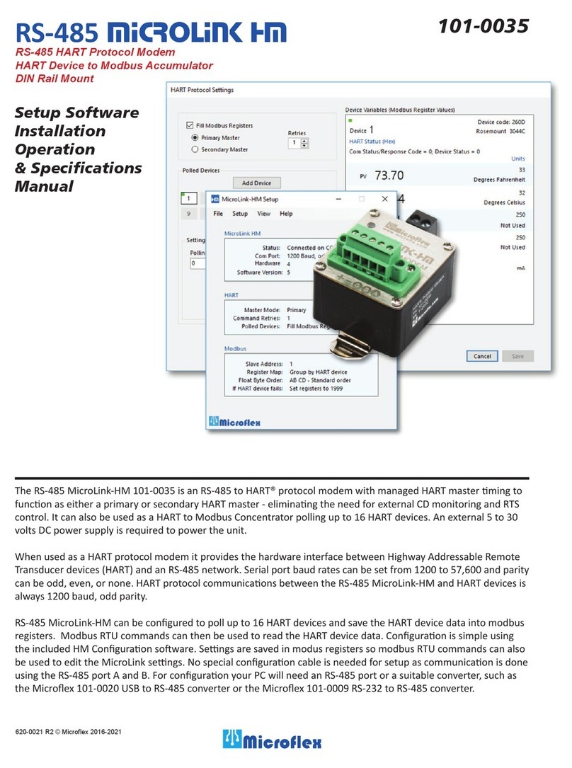
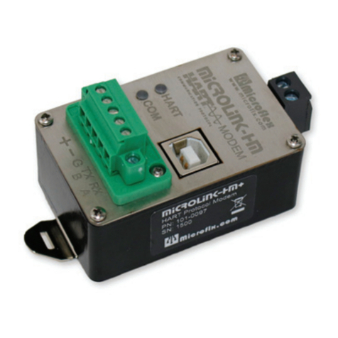
Microflex MicroLink-HM 101-0029 User manual

Setup Software
Installation
Operation
& Specifications
Manual
620-0018 R1.1 © Microfl ex 2016, 2017
101-0029
MicroLinK HM
RS-232 HART Protocol Modem
HART Device to Modbus Accumulator
DIN Rail Mount
The MicroLink-HM 101-0029 is an RS-232 to HART® protocol modem with managed HART master timing to
function as either a primary or secondary HART master - eliminating the need for external CD monitoring and RTS
control. It can also be used as a HART to Modbus Concentrator polling up to 16 HART devices. Power can be taken
from the serial port DTR handshake line or an external 5 to 30 volts DC power supply.
When used as a HART protocol modem it provides the hardware interface between Highway Addressable Remote
Transducer devices (HART) and a computer with an RS-232 port. Unlike many HART modems, communications
direction control is handled internally so there is no need to handle tricky request-to-send (RTS) handshake timing,
greatly simplifying software development and enabling the MicroLink-HM modem to be compatible with common
USB to RS-232 serial converters. Serial port baud rates can be set from 1200 to 57,600 and parity can be odd, even,
or none. HART protocol communications between the MicroLink-HM and HART devices is always 1200 baud, odd
parity.
MicroLink-HM can be confi gured to poll up to 16 HART devices and save the HART device data into modbus reg-
isters. Modbus RTU commands can then be used to read the HART device data. Confi guration is simple using the
included MicroLink-HM Confi guration software. Settings are saved in modus registers so modbus RTU commands
can also be used to edit the MicroLink settings. No special confi guration cable is needed for setup as communica-
tions is done using the MicroLink-HM serial port.

Finding the COM Port Number
You will need to know the COM port number the MicroLink-HM modem is connected to. To see a list of COM ports
installed on your PC, open the Device Manager and select View > Devices by Type. Expand Ports (COM & LPT) to see the
list of available COM ports. MicroLink-HM is compatible with USB to serial converters as well as RS-232 serial ports.
HART Protocol Modem
MicroLink-HM ships confi gured to operate as a HART protocol modem. No additional drivers or external power sourc-
es are needed. Simply connect the 9-pin D-sub connector to a standard RS-232 port. Power can be supplied by the DTR
handshake line or by an external supply. Refer to the Power Supply section in this manual for details.
MicroLink-HM is compatible with most HART confi guration and test software. Included on the CD is the PACTware
FDT frame, HART Protocol DTM, and Microfl ex Generic DTM software. For information on installing PACTware and
the DTM, please reference the PACTware Quick Start Guide.
To function as a HART protocol modem the serial port is typically set to 1200 baud, odd parity. Most HART software
will require this setting. It is possible to set the serial port to other baud rates and parity settings. This is helpful when
connecting the MicroLink-HM to a device that does not off er 1200 baud. In this case MicroLink-HM will receive the
HART command at the higher baud rate then transmit the HART data at 1200 baud, odd parity onto the HART loop. The
1200 baud, odd parity HART reply packet is received by the MicroLink-HM modem and then transmitted back at the
higher baud rate.
If MicroLink-HM is confi gured to Fill Modbus Registers and the serial port detects a HART packet on the RS-232 port,
MicroLink-HM will temporarily switch to HART mode and stop polling devices. HART protocol packets always begin
with the hex FF preamble character. Modbus packets begin with the slave address. If no HART commands are received
over the serial port, MicroLink-HM will return to polling and fi lling modbus registers after 30 seconds. Also, if a mod-
bus command is received MicroLink will exit HART mode and return to polling and fi lling modbus registers.
Connecting to the HART Loop
Connect the two screw terminals to the HART device
or HART loop. Microlink provides electrical isolation
between the HART loop and the serial port so it is safe
to ignore grounding and polarity issues when making
the HART connections. The HART protocol requires
a loop resistance of 230 to 600 ohms, typically 250
ohms. Refer to your equipment installation instructions
for details on connecting a HART master or confi gura-
tion device to the loop.
HART Status LED Operation
The LED on the front panel of the MicroLink-HM is
used to monitor HART communications activity. The
LED will be green while transmitting or sending a pack-
et to your HART protocol devices, and will be red when
HART protocol replies are received.
LOOP
POWER
SUPPLY HART
DEVICE
250Ω
LOOP
POWER
SUPPLY HART
DEVICE
250Ω
Figure 1. Connecting HART modem to device loop.
Connecting across the loop resistor.
Connecting across the HART device.

Mounting
The DIN rail mounting clip is compatible with widely used 35mm EN 50022 rails. It can be snap mounted and removed
from the mounting rail without tools for quick installation and servicing.
Power Supply
The MicroLink-HM is powered through the 9-pin RS-232
connector using the RS-232 Data-Terminal-Ready (DTR)
handshake line - pin 4. When using DTR for power, no external
power supply is required.
An external DC power supply in the 5 to 30Vdc range can also
be used. Connect the positive side to DTR (pin 4) and nega-
tive to Ground (pin 5). Maximum supply current ranges from
2mA at 30 volts to 10.5mA at 5 volts. The RS-232 transmit and
receive will share the ground (pin 5) with the power supply
ground. If external power is used then DTR should not be con-
nected to the mating RS-232 port. Only transmit, receive, and
ground are required for communications.
5 - GROUND
2 - RX ←
3 - TX →
4 - DTR (5-30Vdc)
Figure 2. DB-9 Wiring Diagram
HART Status LED
Power
Supply
RS-232
Driver/Rcvr HART
Modem
Microcontroller
Modbus Register
Tables
TX
RX
CD
RTS
1
2 - RX
3 - TX
4 - DTR
5 - GND
6
7
8
9
9-Pin RS-232
D-Sub Connector HART Loop
Terminals
HART Status LED
MicroLink-HM Block Diagram
RS-232 Cable Schematic
The RS-232 extension cable connecting the Mi-
croLink-HM to the RS-232 serial port requires only
4 wires. If external power is used then only trans-
mit, receive, and ground are needed on the RS-232
port side.
)(0$/( 0$/(
5;
7;
'75
*1'
56
3257
0LFUR/LQN+0
)(0$/( 0$/(
5;
7;
'75
*1'
WR9GF
*5281'
Power from DTR line External power supply

Setting COM Port
The MicroLink-HM software must be set to use the same COM
port that the modem is connected to. From the top menu select
Setup>Com Port. Choose the COM port number from the list
of available ports. After choosing, click Connect to attempt to
connect using the settings selected. The connection process will
fi rst try the last good baud rate and parity settings. If it fails to
connect the process will work
through other settings to try to
fi nd the correct MicroLink-HM
settings for communications. If it
still does not connect - verify that
you have chosen the correct COM
number, connections are correct,
and power is on before trying
again.
MicroLink-HM HART - Modbus Accumulator
In addition to being an RS-232 HART Protocol Modem, the MicroLink HM can be set to collect and store process
variable information from up to 16 HART devices. HART devices are continuously polled and variable information
is accumulated into a table of Modbus registers. Using the MicroLink-HM serial port, the registers can be read using
Modbus RTU command 3. Variable data can be read as 16 bit integers or 32 bit fl oating point. Up to 4 variables for each
polled HART device.
In the accumulate mode, MicroLink-HM will function as a HART master (primary or secondary) polling devices and
storing variable values into registers. No additional HART software is needed. The HART loop may contain a single
device or up to 16 devices. When more than one device is in the loop each HART device must have a unique HART
polling address. The address for each device is set before wiring the device into the multi-drop loop. The device polling
address for each device is stored in the MicroLink-HM using the MicroLink-HM confi guration software.
Modbus slave address, baud rate, parity, and other settings are set using the MicroLink-HM confi guration software.
Confi guration is done using the same RS-232 port that Modbus will use so no additional setup cable is required. After the
confi guration is completed, the RS-232 port is connected to the Modbus controller. At power on the MicroLink-HM will
begin polling and accumulating values. Modbus RTU command 3 is used to read the accumulated values.
MicroLink HM Installation - Windows
The MicroLink-HM confi guration software is included on a CD with the unit. Simply insert the CD and follow the on-
screen prompts to install the software. If AutoRun is not confi gured to run the CD fi le when the CD is inserted you will
need to navigate to the SetupHM.exe fi le on the CD and double-click the fi le name to run it.
After Installation the MicroLink-HM icon will be added to your system.
If you do not have a CD Rom device on your computer, contact sales@microfl x.com to inquire
about a digital download version of the software.
Home Screen
The home screen displays a summary of the MicroLink-HM
status, HART modem settings, and Modbus settings. Use the top
drop-down menus to confi gure the MicroLink-HM modem.
Figure 3. COM Port List.
Figure 4. MicroLink-HM Setup home screen.

Polling HART Devices - Fill Modbus Registers
To enable Modbus register accumulation, check the Fill Modbus Registers option. The Hart Protocol Settings window will
expand to show the Polled Devices settings.
Retries
If a HART devices is polled but does not respond, or errors are detected, MicroLink-HM can retry up to 3 times before
indicating a bad device. If a device is not responding the Modbus values are fi lled with Hart Device Failed register val-
ues - setup is done in the Modbus confi guration section.
Polled Devices
In the example screen shot (Figure 5), MicroLink-HM is set to poll one HART device using polling address 0 and will
retry 1 time before reporting a communications error. The Device Variables (Modbus Register Values) box on the right
displays the register values for the active polled device. Click Add Device to add a polled HART device. Be sure to set
the Polling Address
for each device. Each
device must have a
unique HART polling
address. Polling
addresses must be
setup for each HART
device before it can
be connected to a
multi-drop HART
loop and can be set
from 1 to 63.
Address 0 can only be
used when one device
is in the HART loop.
Polling addresses
16-63 should only be
used with HART revi-
sions 6 and higher.
For HART 3-5 use
addresses 1-15 for
multi-drop systems.
HART Protocol Settings
With Fill Modbus Registers unchecked, MicroLink-HM will function as a standard HART protocol modem and not poll
HART devices to fi ll Modbus registers. In this mode HART packets are received and then retransmitted at the HART
1200 baud, odd parity. Received reply packets are retransmitted at the
selected baud rate. RTS timing and carrier detect are handled internally
by the MicroLink-HM allowing RS-232 communications at higher than
1200 baud. HART loop data is handled at the standard HART protocol
1200 baud, odd parity but because MicroLink-HM buff ers the data
the RS-232 port can be set for higher rates as well as odd, even, or no
parity. Port settings can be set in the Modbus Settings section.
Since MicroLink-HM manages network timing it needs to be confi g-
ured for either a primary or secondary master. Portable confi guration
modems are typically set to be secondary masters.
Figure 5. HART protocol settings dialog when fi lling modbus registers is enabled.

Modbus - RTU Setup
Modbus-RTU Settings can be accessed and changed by clicking Setup>Modbus from the top drop-down menu.
Modbus Address
Each device on a Modbus network must have a unique address. Set
this to match the address that your Modbus master will use to com-
municate with the MicroLink-HM. The Modbus address can be set
to any value from 1 to 247. The MicroLink-HM confi guration soft-
ware will discover this address as part of the connection process.
Baud Rate & Parity
The MicroLink-HM baud rate and parity must be set to the
same settings as your Modbus master. If you are using the Mi-
croLink-HM as a HART protocol modem these should be set to
1200 baud, odd parity. Click Use HART Protocol Settings to set the
correct values for a HART modem.
Holding Registers Map
Accumulated data is stored in Modbus registers that are grouped or
mapped by HART device or by variable type. Choose the register
map that best fi ts your application. Register maps can be viewed
using the MicroLink-HM confi guration software. From the top
drop-down menu select View -> Modbus Registers Maps (Figure 7.)
Decimal Places
When device data is stored into a 16 bit signed Modbus register the value can range from -32768 to 32767. To allow the
16 bit integer to represent a smaller number and include fractional information, the number of decimal places is stored in
a separate Modbus register and applied later. The number of decimal places can be set from 0 to 5. Decimal places can
be set for each variable. The Device Variables box shows the eff ect of the decimal place setting. Decimal place settings are
not used for the Modus fl oating point register values.
Figure 6. Modbus settings dialog.
Figure 7. Menu for viewing modbus register maps.
Floating Point Byte Order
Modbus 32 bit fl oating point numbers are stored in two
consecutive 16 bit registers using the IEEE-754 standard
big endian byte order (AB-CD). The most signifi cant byte
(A) is sent fi rst. For compatibility with some modbus
systems you may need to use the word swapped format
(CD-AB).
HART Device Failed Register Value
If a polled HART device fails to respond, or has commu-
nications errors it will retry for the number of times set
in the HART Protocol Settings dialog. If after retries the
device does not respond you can choose to hold the last
value, set to a preset number, or set to the IEEE-754 NaN
fl oating point value. This can help the modbus master
determine when a HART device is no longer responding.

Setup Registers
The MicroLink-HM confi guration can be changed using the setup and confi guration software or by writing to modbus
registers using modbus-RTU commands 6 or 16. Command 6 writes to a single register and command 16 writes to a
range of modbus registers. The confi guration register values are saved in nonvolatile memory and are not lost when
MicroLink-HM power is removed.
HART Settings
Bits 9, 8 HART failed mode 0 = Hold last value after HART retries
1 = Preset to register 772 value after HART retries
2 = Preset to IEEE-754 NaN (0 for integers)
Bits 7, 6 HART poll retries Sets number of HART device poll retries from 1 to 3.
After poll retries, the HART failed mode value is stored in the variable register.
Bits 3 - 0 Number of polled devices -1 Range is 0 to 15. 0 = 1 polled device. 15 = 16 polled devices.
ϭϱϭϰϭϯϭϮϭϭϭϬϵϴϳϲϱϰϯϮϭϬ
,Zd&ĂŝůĞĚDŽĚĞ;ŝƚϭͿ
,Zd&ĂŝůĞĚDŽĚĞ;ŝƚϬͿ
,ZdZĞƚƌŝĞƐ;ŝƚϭͿ
,ZdZĞƚƌŝĞƐ;ŝƚϬͿ
Ϭс&ŝůůZĞŐŝƐƚĞƌƐϭс,ZdDŽĚĞŵ
ϭсWƌŝŵĂƌLJϬс^ĞĐŽŶĚĂƌLJDĂƐƚĞƌ
EƵŵďĞƌŽĨƉŽůůĞĚĚĞǀŝĐĞƐͲϭ
ϬсϭWŽůůĞĚĞǀŝĐĞ;ϬƚŽϭϱͿ
ϳϳϯͲ,Zd^ĞƚƚŝŶŐƐ
DŽĚďƵƐ
ZĞŐŝƐƚĞƌ ĞƐĐƌŝƉƚŝŽŶ;ŚŝŐŚďLJƚĞůŽǁďLJƚĞͿ
ϳϳϮ ,Zd&ĂŝůĞĚŽĚĞWƌĞƐĞƚsĂůƵĞ
ϳϳϯ ,ZdDŽĚĞ^ĞƚƚŝŶŐƐ
ϳϳϰ DŽĚďƵƐ^ĞƚƚŝŶŐƐ
ϳϳϱ DŽĚďƵƐWŽƌƚ^ĞƚƚŝŶŐƐ
ϳϳϲ ,ĂƌĚǁĂƌĞZĞǀ^ŽĨƚǁĂƌĞZĞǀ
ϳϳϳ WŽůůĞĚĚĞǀŝĐĞƐƚĂƚƵƐ

Serial Port Settings
ϭϱϭϰϭϯϭϮϭϭϭϬϵϴϳϲϱϰϯϮϭϬ
ϭсKĚĚƉĂƌŝƚLJ
ϭсǀĞŶƉĂƌŝƚLJ
ĂƵĚ;ďŝƚϯͿ
ĂƵĚ;ďŝƚϮͿ
ĂƵĚ;ďŝƚϭͿ
ĂƵĚ;ďŝƚϬͿ
ϳϳϱͲDŽĚďƵƐWŽƌƚ^ĞƚƚŝŶŐƐ
DŽĚďƵƐ^ůĂǀĞĚĚƌĞƐƐ;ϭͲϮϰϳͿ
Bits 13, 12
00 = No parity
01 = Even
10 = Odd
Mode Settings
Bit 9 - Floating point value byte order 0 = Standard byte order (AB - CD)
1 = Swapped words (CD - AB)
Bit 8 - Modbus device map 0 = Map register data by HART device
1 = Map register data by variable type
ϭϱϭϰϭϯϭϮϭϭϭϬϵϴϳϲϱϰϯϮϭϬ
ϬсĨůŽĂƚďLJƚĞŽƌĚĞƌϭс
ϬсďLJĞǀŝĐĞDĂƉϭсďLJsĂƌŝĂďůĞDĂƉ
ϳϳϰͲDŽĚĞ^ĞƚƚŝŶŐƐ
Bits 11 - 8
1 = 1200 Baud
2 = 2400
3 = 4800
4 = 9600
5 = 14400
6 = 19200
7 = 38400
8 = 57600
9 = 115200

,Zd DŽĚďƵƐ
ĞǀŝĐĞ ZĞŐŝƐƚĞƌ ĞƐĐƌŝƉƚŝŽŶ;ŚŝŐŚďLJƚĞůŽǁďLJƚĞͿ
ϭ ϳϬϬ WƌĞĂŵďůĞƐDĂŶŽĚĞŽƌdLJƉĞ
ϳϬϭ ĞǀŝĐĞdLJƉĞ/ϭ
ϳϬϮ /Ϯ/ϯ
Ϯ ϳϬϯ WƌĞĂŵďůĞƐDĂŶŽĚĞŽƌdLJƉĞ
ϳϬϰ ĞǀŝĐĞdLJƉĞ/ϭ
ϳϬϱ /Ϯ/ϯ
ϯ ϳϬϲ WƌĞĂŵďůĞƐDĂŶŽĚĞŽƌdLJƉĞ
ϳϬϳ ĞǀŝĐĞdLJƉĞ/ϭ
ϳϬϴ /Ϯ/ϯ
ϰ ϳϬϵ WƌĞĂŵďůĞƐDĂŶŽĚĞŽƌdLJƉĞ
ϳϭϬ ĞǀŝĐĞdLJƉĞ/ϭ
ϳϭϭ /Ϯ/ϯ
ϱ ϳϭϮ WƌĞĂŵďůĞƐDĂŶŽĚĞŽƌdLJƉĞ
ϳϭϯ ĞǀŝĐĞdLJƉĞ/ϭ
ϳϭϰ /Ϯ/ϯ
ϲ ϳϭϱ WƌĞĂŵďůĞƐDĂŶŽĚĞŽƌdLJƉĞ
ϳϭϲ ĞǀŝĐĞdLJƉĞ/ϭ
ϳϭϳ /Ϯ/ϯ
ϳ ϳϭϴ WƌĞĂŵďůĞƐDĂŶŽĚĞŽƌdLJƉĞ
ϳϭϵ ĞǀŝĐĞdLJƉĞ/ϭ
ϳϮϬ /Ϯ/ϯ
ϴ ϳϮϭ WƌĞĂŵďůĞƐDĂŶŽĚĞŽƌdLJƉĞ
ϳϮϮ ĞǀŝĐĞdLJƉĞ/ϭ
ϳϮϯ /Ϯ/ϯ
ϵ ϳϮϰ WƌĞĂŵďůĞƐDĂŶŽĚĞŽƌdLJƉĞ
ϳϮϱ ĞǀŝĐĞdLJƉĞ/ϭ
ϳϮϲ /Ϯ/ϯ
ϭϬ ϳϮϳ WƌĞĂŵďůĞƐDĂŶŽĚĞŽƌdLJƉĞ
ϳϮϴ ĞǀŝĐĞdLJƉĞ/ϭ
ϳϮϵ /Ϯ/ϯ
ϭϭ ϳϯϬ WƌĞĂŵďůĞƐDĂŶŽĚĞŽƌdLJƉĞ
ϳϯϭ ĞǀŝĐĞdLJƉĞ/ϭ
ϳϯϮ /Ϯ/ϯ
ϭϮ ϳϯϯ WƌĞĂŵďůĞƐDĂŶŽĚĞŽƌdLJƉĞ
ϳϯϰ ĞǀŝĐĞdLJƉĞ/ϭ
ϳϯϱ /Ϯ/ϯ
ϭϯ ϳϯϲ WƌĞĂŵďůĞƐDĂŶŽĚĞŽƌdLJƉĞ
ϳϯϳ ĞǀŝĐĞdLJƉĞ/ϭ
ϳϯϴ /Ϯ/ϯ
ϭϰ ϳϯϵ WƌĞĂŵďůĞƐDĂŶŽĚĞŽƌdLJƉĞ
ϳϰϬ ĞǀŝĐĞdLJƉĞ/ϭ
ϳϰϭ /Ϯ/ϯ
ϭϱ ϳϰϮ WƌĞĂŵďůĞƐDĂŶŽĚĞŽƌdLJƉĞ
ϳϰϯ ĞǀŝĐĞdLJƉĞ/ϭ
ϳϰϰ /Ϯ/ϯ
ϭϲ ϳϰϱ WƌĞĂŵďůĞƐDĂŶŽĚĞŽƌdLJƉĞ
ϳϰϲ ĞǀŝĐĞdLJƉĞ/ϭ
ϳϰϳ /Ϯ/ϯ
Polled HART Devices Long Address Table
Device ID information is read from each polled device using the devices polling address and HART command 0. The
reply to command 0 for each polled device is used to populate the long address table. When MicroLink-HM needs to
poll for the device variables, using HART command 3, this table holds the information needed to build the 5-byte long
address. Table values can be read using Modbus-RTU command 3. Only the polled device you have confi gured will
contain valid information. The table is updated after each valid device poll.

DŽĚďƵƐ ,ZdĞǀŝĐĞWŽůůŝŶŐĚĚƌĞƐƐ
ZĞŐŝƐƚĞƌ ;ŚŝŐŚďLJƚĞůŽǁďLJƚĞͿ
ϳϰϴ ĞǀŝĐĞϭĞǀŝĐĞϮ
ϳϰϵ ĞǀŝĐĞϯĞǀŝĐĞϰ
ϳϱϬ ĞǀŝĐĞϱĞǀŝĐĞϲ
ϳϱϭ ĞǀŝĐĞϳĞǀŝĐĞϴ
ϳϱϮ ĞǀŝĐĞϵĞǀŝĐĞϭϬ
ϳϱϯ ĞǀŝĐĞϭϭĞǀŝĐĞϭϮ
ϳϱϰ ĞǀŝĐĞϭϯĞǀŝĐĞϭϰ
ϳϱϱ ĞǀŝĐĞϭϱĞǀŝĐĞϭϲ
HART Device Polling Address Table
The polling address for each polled device is stored in this table. Two polling addresses in each 16 bit register. If ad-
dress 0 is used then only one device can be polled and Device 1 should be set to 0. Address 0 is not valid in multi-drop
systems. For HART devices with HART revision 3 through 5 you should use polling addresses 1 - 15. Addresses 16-63
require HART revision 6 or higher.
,Zd DŽĚďƵƐ EƵŵďĞƌŽĨĞĐŝŵĂůWůĂĐĞƐ
ĞǀŝĐĞ ZĞŐŝƐƚĞƌ ĞƐĐƌŝƉƚŝŽŶ;ŚŝŐŚďLJƚĞůŽǁďLJƚĞͿ
ϭ ϳϱϲ WsͲ^dsͲ&s
Ϯ ϳϱϳ WsͲ^dsͲ&s
ϯ ϳϱϴ WsͲ^dsͲ&s
ϰ ϳϱϵ WsͲ^dsͲ&s
ϱ ϳϲϬ WsͲ^dsͲ&s
ϲ ϳϲϭ WsͲ^dsͲ&s
ϳ ϳϲϮ WsͲ^dsͲ&s
ϴ ϳϲϯ WsͲ^dsͲ&s
ϵ ϳϲϰ WsͲ^dsͲ&s
ϭϬ ϳϲϱ WsͲ^dsͲ&s
ϭϭ ϳϲϲ WsͲ^dsͲ&s
ϭϮ ϳϲϳ WsͲ^dsͲ&s
ϭϯ ϳϲϴ WsͲ^dsͲ&s
ϭϰ ϳϲϵ WsͲ^dsͲ&s
ϭϱ ϳϳϬ WsͲ^dsͲ&s
ϭϲ ϳϳϭ WsͲ^dsͲ&s
Number of Decimal Places Table
When storing the HART variable data in 16-bit modbus registers the maximum range is -32768 to 32767. To increase the
possible resolution, the variable value read from the HART device is decimal position adjusted before being saved in the
16-bit register. When the register is read, the value must be corrected by the number of decimal placed to produce the
correct value. The number of decimal places for each variable occupies 4-bits in the register with one register for each
polled device.
Decimals Variable Range
0 -32768 to 32767
1 -3276.8 to 3276.7
2 -327.68 to 327.67
3 -32.768 to 32.767
4 -3.2768 to 3.2767
5 -0.32768 to 0.32767

ZĞŐŝƐƚĞƌ ĞƐĐƌŝƉƚŝŽŶ
ϳ >ŽŽƉƵƌƌĞŶƚ/ŶƚĞŐĞ
ƌ
ϮϱϰϮϱ
ϱ
>ŽŽƉƵƌƌĞŶƚ&ůŽĂ
ƚ
ĞǀŝĐĞϰ
ZĞŐŝƐƚĞƌ ĞƐĐƌŝƉƚŝŽŶ ZĞŐŝƐƚĞƌ ĞƐĐƌŝƉƚŝŽŶ
Ϭ Ws/ŶƚĞŐĞƌ Ϯϰ Ws/ŶƚĞŐĞƌ
ϭ ^s/ŶƚĞŐĞƌ Ϯϱ ^s/ŶƚĞŐĞƌ
Ϯ ds/ŶƚĞŐĞƌ Ϯϲ ds/ŶƚĞŐĞƌ
ϯ &s/ŶƚĞŐĞƌ Ϯϳ &s/ŶƚĞŐĞƌ
ϰ ,Zd^ƚĂƚƵƐ Ϯϴ ,Zd^ƚĂƚƵƐ
ϱ D^сWshKD>^с^shK
D
Ϯϵ D^сWshKD>^с^shK
D
ϲ D^сdshKD>^с&shK
D
ϯϬ D^сdshKD>^с&shK
D
ϮϱϲϮϱ
ϳ
Ws&ůŽĂƚ ϮϴϬϮϴ
ϭ
Ws&ůŽĂƚ
ϮϱϴϮϱ
ϵ
^s&ůŽĂƚ ϮϴϮϮϴϯ ^s&ůŽĂƚ
ϮϲϬϮϲ
ϭ
ds&ůŽĂƚ ϮϴϰϮϴ
ϱ
ds&ůŽĂƚ
ϮϲϮϮϲϯ &s&ůŽĂƚ ϮϴϲϮϴ
ϳ
&s&ůŽĂƚ
ĞǀŝĐĞϮ ĞǀŝĐĞϱ
ϴ Ws/ŶƚĞŐĞƌ ϯϮ Ws/ŶƚĞŐĞƌ
ϵ ^s/ŶƚĞŐĞƌ ϯϯ ^s/ŶƚĞŐĞƌ
ϭϬ ds/ŶƚĞŐĞƌ ϯϰ ds/ŶƚĞŐĞƌ
ϭϭ &s/ŶƚĞŐĞƌ ϯϱ &s/ŶƚĞŐĞƌ
ϭϮ ,Zd^ƚĂƚƵƐ ϯϲ ,Zd^ƚĂƚƵƐ
ϭϯ D^сWshKD>^с^shK
D
ϯϳ D^сWshKD>^с^shK
D
ϭϰ D^сdshKD>^с&shK
D
ϯϴ D^сdshKD>^с&shK
D
ϮϲϰϮϲ
ϱ
Ws&ůŽĂƚ ϮϴϴϮϴ
ϵ
Ws&ůŽĂƚ
ϮϲϲϮϲ
ϳ
^s&ůŽĂƚ ϮϵϬϮϵ
ϭ
^s&ůŽĂƚ
ϮϲϴϮϲ
ϵ
ds&ůŽĂƚ ϮϵϮϮϵϯ ds&ůŽĂƚ
ϮϳϬϮϳ
ϭ
&s&ůŽĂƚ ϮϵϰϮϵ
ϱ
&s&ůŽĂƚ
ĞǀŝĐĞϯ ĞǀŝĐĞϲ
ϭϲ Ws/ŶƚĞŐĞƌ ϰϬ Ws/ŶƚĞŐĞƌ
ϭϳ ^s/ŶƚĞŐĞƌ ϰϭ ^s/ŶƚĞŐĞƌ
ϭϴ ds/ŶƚĞŐĞƌ ϰϮ ds/ŶƚĞŐĞƌ
ϭϵ &s/ŶƚĞŐĞƌ ϰϯ &s/ŶƚĞŐĞƌ
ϮϬ ,Zd^ƚĂƚƵƐ ϰϰ ,Zd^ƚĂƚƵƐ
Ϯϭ D^сWshKD>^с^shK
D
ϰϱ D^сWshKD>^с^shK
D
ϮϮ D^сdshKD>^с&shK
D
ϰϲ D^сdshKD>^с&shK
D
ϮϳϮϮϳϯ Ws&ůŽĂƚ ϮϵϲϮϵ
ϳ
Ws&ůŽĂƚ
ϮϳϰϮϳ
ϱ
^s&ůŽĂƚ ϮϵϴϮϵ
ϵ
^s&ůŽĂƚ
ϮϳϲϮϳ
ϳ
ds&ůŽĂƚ ϯϬϬϯϬ
ϭ
ds&ůŽĂƚ
ϮϳϴϮϳ
ϵ
&s&ůŽĂƚ ϯϬϮϯϬϯ &s&ůŽĂƚ
ĞǀŝĐĞϭ
Modbus Register Map - Grouped by HART Device (1 of 3)

Modbus Register Map - Grouped by HART Device (2 of 3)
ĞǀŝĐĞϳ ĞǀŝĐĞϭϬ
ZĞŐŝƐƚĞƌ ĞƐĐƌŝƉƚŝŽŶ ZĞŐŝƐƚĞƌ ĞƐĐƌŝƉƚŝŽŶ
ϰϴ Ws/ŶƚĞŐĞƌ ϳϮ Ws/ŶƚĞŐĞƌ
ϰϵ ^s/ŶƚĞŐĞƌ ϳϯ ^s/ŶƚĞŐĞƌ
ϱϬ ds/ŶƚĞŐĞƌ ϳϰ ds/ŶƚĞŐĞƌ
ϱϭ &s/ŶƚĞŐĞƌ ϳϱ &s/ŶƚĞŐĞƌ
ϱϮ ,Zd^ƚĂƚƵƐ ϳϲ ,Zd^ƚĂƚƵƐ
ϱϯ D^сWshKD>^с^shK
D
ϳϳ D^сWshKD>^с^shK
D
ϱϰ D^сdshKD>^с&shK
D
ϳϴ D^сdshKD>^с&shK
D
ϯϬϰϯϬ
ϱ
Ws&ůŽĂƚ ϯϮϴϯϮ
ϵ
Ws&ůŽĂƚ
ϯϬϲϯϬ
ϳ
^s&ůŽĂƚ ϯϯϬϯϯ
ϭ
^s&ůŽĂƚ
ϯϬϴϯϬ
ϵ
ds&ůŽĂƚ ϯϯϮϯϯϯ ds&ůŽĂƚ
ϯϭϬϯϭ
ϭ
&s&ůŽĂƚ ϯϯϰϯϯ
ϱ
&s&ůŽĂƚ
ĞǀŝĐĞϴ ĞǀŝĐĞƌϭϭ
ϱϲ Ws/ŶƚĞŐĞƌ ϴϬ Ws/ŶƚĞŐĞƌ
ϱϳ ^s/ŶƚĞŐĞƌ ϴϭ ^s/ŶƚĞŐĞƌ
ϱϴ ds/ŶƚĞŐĞƌ ϴϮ ds/ŶƚĞŐĞƌ
ϱϵ &s/ŶƚĞŐĞƌ ϴϯ &s/ŶƚĞŐĞƌ
ϲϬ ,Zd^ƚĂƚƵƐ ϴϰ ,Zd^ƚĂƚƵƐ
ϲϭ D^сWshKD>^с^shK
D
ϴϱ D^сWshKD>^с^shK
D
ϲϮ D^сdshKD>^с&shK
D
ϴϲ D^сdshKD>^с&shK
D
ϯϭϮϯϭϯ Ws&ůŽĂƚ ϯϯϲϯϯ
ϳ
Ws&ůŽĂƚ
ϯϭϰϯϭ
ϱ
^s&ůŽĂƚ ϯϯϴϯϯ
ϵ
^s&ůŽĂƚ
ϯϭϲϯϭ
ϳ
ds&ůŽĂƚ ϯϰϬϯϰ
ϭ
ds&ůŽĂƚ
ϯϭϴϯϭ
ϵ
&s&ůŽĂƚ ϯϰϮϯϰϯ &s&ůŽĂƚ
ĞǀŝĐĞϵ ĞǀŝĐĞϭϮ
ϲϰ Ws/ŶƚĞŐĞƌ ϴϴ Ws/ŶƚĞŐĞƌ
ϲϱ ^s/ŶƚĞŐĞƌ ϴϵ ^s/ŶƚĞŐĞƌ
ϲϲ ds/ŶƚĞŐĞƌ ϵϬ ds/ŶƚĞŐĞƌ
ϲϳ &s/ŶƚĞŐĞƌ ϵϭ &s/ŶƚĞŐĞƌ
ϲϴ ,Zd^ƚĂƚƵƐ ϵϮ ,Zd^ƚĂƚƵƐ
ϲϵ D^сWshKD>^с^shK
D
ϵϯ D^сWshKD>^с^shK
D
ϳϬ D^сdshKD>^с&shK
D
ϵϰ D^сdshKD>^с&shK
D
ϯϮϬϯϮ
ϭ
Ws&ůŽĂƚ ϯϰϰϯϰ
ϱ
Ws&ůŽĂƚ
ϯϮϮϯϮϯ ^s&ůŽĂƚ ϯϰϲϯϰ
ϳ
^s&ůŽĂƚ
ϯϮϰϯϮ
ϱ
ds&ůŽĂƚ ϯϰϴϯϰ
ϵ
ds&ůŽĂƚ
ϯϮϲϯϮ
ϳ
&s&ůŽĂƚ ϯϱϬϯϱ
ϭ
&s&ůŽĂƚ

Modbus Register Map - Grouped by HART Device (3 of 3)
ĞǀŝĐĞϭϯ ĞǀŝĐĞϭϱ
ZĞŐŝƐƚĞƌ ĞƐĐƌŝƉƚŝŽŶ ZĞŐŝƐƚĞƌ ĞƐĐƌŝƉƚŝŽŶ
ϵϲ Ws/ŶƚĞŐĞƌ ϭϭϮ Ws/ŶƚĞŐĞƌ
ϵϳ ^s/ŶƚĞŐĞƌ ϭϭϯ ^s/ŶƚĞŐĞƌ
ϵϴ ds/ŶƚĞŐĞƌ ϭϭϰ ds/ŶƚĞŐĞƌ
ϵϵ &s/ŶƚĞŐĞƌ ϭϭϱ &s/ŶƚĞŐĞƌ
ϭϬϬ ,Zd^ƚĂƚƵƐ ϭϭϲ ,Zd^ƚĂƚƵƐ
ϭϬϭ D^сWshKD>^с^shK
D
ϭϭϳ D^сWshKD>^с^shK
D
ϭϬϮ D^сdshKD>^с&shK
D
ϭϭϴ D^сdshKD>^с&shK
D
ϯϱϮϯϱϯ Ws&ůŽĂƚ ϯϲϴϯϲ
ϵ
Ws&ůŽĂƚ
ϯϱϰϯϱ
ϱ
^s&ůŽĂƚ ϯϳϬϯϳ
ϭ
^s&ůŽĂƚ
ϯϱϲϯϱ
ϳ
ds&ůŽĂƚ ϯϳϮϯϳϯ ds&ůŽĂƚ
ϯϱϴϯϱ
ϵ
&s&ůŽĂƚ ϯϳϰϯϳ
ϱ
&s&ůŽĂƚ
ĞǀŝĐĞϭϰ ĞǀŝĐĞϭϲ
ϭϬϰ Ws/ŶƚĞŐĞƌ ϭϮϬ Ws/ŶƚĞŐĞƌ
ϭϬϱ ^s/ŶƚĞŐĞƌ ϭϮϭ ^s/ŶƚĞŐĞƌ
ϭϬϲ ds/ŶƚĞŐĞƌ ϭϮϮ ds/ŶƚĞŐĞƌ
ϭϬϳ &s/ŶƚĞŐĞƌ ϭϮϯ &s/ŶƚĞŐĞƌ
ϭϬϴ ,Zd^ƚĂƚƵƐ ϭϮϰ ,Zd^ƚĂƚƵƐ
ϭϬϵ D^сWshKD>^с^shK
D
ϭϮϱ D^сWshKD>^с^shK
D
ϭϭϬ D^сdshKD>^с&shK
D
ϭϮϲ D^сdshKD>^с&shK
D
ϯϲϬϯϲ
ϭ
Ws&ůŽĂƚ ϯϳϲϯϳ
ϳ
Ws&ůŽĂƚ
ϯϲϮϯϲϯ ^s&ůŽĂƚ ϯϳϴϯϳ
ϵ
^s&ůŽĂƚ
ϯϲϰϯϲ
ϱ
ds&ůŽĂƚ ϯϴϬϯϴ
ϭ
ds&ůŽĂƚ
ϯϲϲϯϲ
ϳ
&s&ůŽĂƚ ϯϴϮϯϴϯ &s&ůŽĂƚ

Modbus Register Map - Grouped by Variable Type
ZĞǀϭ
ϭϭϮ
ϮϱϰϮϱϱ
,Zd Ws ^s ds &s ,Zd hKD hKD
ĞǀŝĐĞ /ŶƚĞŐĞƌ /ŶƚĞŐĞƌ /ŶƚĞŐĞƌ /ŶƚĞŐĞƌ ^ƚĂƚƵƐ Ws^s ds&s
ϭ Ϭ ϭϲ ϯϮ ϰϴ ϲϰ ϴϬ ϵϲ
Ϯ ϭ ϭϳ ϯϯ ϰϵ ϲϱ ϴϭ ϵϳ
ϯ Ϯ ϭϴ ϯϰ ϱϬ ϲϲ ϴϮ ϵϴ
ϰ ϯ ϭϵ ϯϱ ϱϭ ϲϳ ϴϯ ϵϵ
ϱ ϰ ϮϬ ϯϲ ϱϮ ϲϴ ϴϰ ϭϬϬ
ϲ ϱ Ϯϭ ϯϳ ϱϯ ϲϵ ϴϱ ϭϬϭ
ϳ ϲ ϮϮ ϯϴ ϱϰ ϳϬ ϴϲ ϭϬϮ
ϴ ϳ Ϯϯ ϯϵ ϱϱ ϳϭ ϴϳ ϭϬϯ
ϵ ϴ Ϯϰ ϰϬ ϱϲ ϳϮ ϴϴ ϭϬϰ
ϭϬ ϵ Ϯϱ ϰϭ ϱϳ ϳϯ ϴϵ ϭϬϱ
ϭϭ ϭϬ Ϯϲ ϰϮ ϱϴ ϳϰ ϵϬ ϭϬϲ
ϭϮ ϭϭ Ϯϳ ϰϯ ϱϵ ϳϱ ϵϭ ϭϬϳ
ϭϯ ϭϮ Ϯϴ ϰϰ ϲϬ ϳϲ ϵϮ ϭϬϴ
ϭϰ ϭϯ Ϯϵ ϰϱ ϲϭ ϳϳ ϵϯ ϭϬϵ
ϭϱ ϭϰ ϯϬ ϰϲ ϲϮ ϳϴ ϵϰ ϭϭϬ
ϭϲ ϭϱ ϯϭ ϰϳ ϲϯ ϳϵ ϵϱ ϭϭϭ
,Zd Ws ^s ds Ys
ĞǀŝĐĞ &ůŽĂƚ &ůŽĂƚ &ůŽĂƚ &ůŽĂƚ
ϭ ϮϱϲϮϱϳ ϮϴϴϮϴϵ ϯϮϬϯϮϭ ϯϱϮϯϱϯ
Ϯ ϮϱϴϮϱϵ ϮϵϬϮϵϭ ϯϮϮϯϮϯ ϯϱϰϯϱϱ
ϯ ϮϲϬϮϲϭ ϮϵϮϮϵϯ ϯϮϰϯϮϱ ϯϱϲϯϱϳ
ϰ ϮϲϮϮϲϯ ϮϵϰϮϵϱ ϯϮϲϯϮϳ ϯϱϴϯϱϵ
ϱ ϮϲϰϮϲϱ ϮϵϲϮϵϳ ϯϮϴϯϮϵ ϯϲϬϯϲϭ
ϲ ϮϲϲϮϲϳ ϮϵϴϮϵϵ ϯϯϬϯϯϭ ϯϲϮϯϲϯ
ϳ ϮϲϴϮϲϵ ϯϬϬϯϬϭ ϯϯϮϯϯϯ ϯϲϰϯϲϱ
ϴ ϮϳϬϮϳϭ ϯϬϮϯϬϯ ϯϯϰϯϯϱ ϯϲϲϯϲϳ
ϵ ϮϳϮϮϳϯ ϯϬϰϯϬϱ ϯϯϲϯϯϳ ϯϲϴϯϲϵ
ϭϬ ϮϳϰϮϳϱ ϯϬϲϯϬϳ ϯϯϴϯϯϵ ϯϳϬϯϳϭ
ϭϭ ϮϳϲϮϳϳ ϯϬϴϯϬϵ ϯϰϬϯϰϭ ϯϳϮϯϳϯ
ϭϮ ϮϳϴϮϳϵ ϯϭϬϯϭϭ ϯϰϮϯϰϯ ϯϳϰϯϳϱ
ϭϯ ϮϴϬϮϴϭ ϯϭϮϯϭϯ ϯϰϰϯϰϱ ϯϳϲϯϳϳ
ϭϰ ϮϴϮϮϴϯ ϯϭϰϯϭϱ ϯϰϲϯϰϳ ϯϳϴϯϳϵ
ϭϱ ϮϴϰϮϴϱ ϯϭϲϯϭϳ ϯϰϴϯϰϵ ϯϴϬϯϴϭ
ϭϲ ϮϴϲϮϴϳ ϯϭϴϯϭϵ ϯϱϬϯϱϭ ϯϴϮϯϴϯ
>ŽŽƉƵƌƌĞŶƚͲ/ŶƚĞŐĞƌ
>ŽŽƉƵƌƌĞŶƚͲ&ůŽĂƚ
ϯϮͲďŝƚ&ůŽĂƚZĞŐŝƐƚĞƌƐ
ϭϲͲďŝƚ^ŝŐŶĞĚZĞŐŝƐƚĞƌƐ ϭϲͲďŝƚhŶƐŝŐŶĞĚ

Enclosure
Polycarbonate plastic with Stainless Steel Cover
Weight ..................................................................................... 5 ounces
Mounting ................................................................ 35mm DIN Rail Clip
RS-232 Serial Port
Connector ............................................................9-Pin Female D-Shell
Receive Data .................................................................................Pin 2
Transmit Data .................................................................................Pin 3
Data Terminal Ready (DTR) ...........................................................Pin 4
Ground............................................................................................Pin 5
HART
Termination ............................ Pluggable Screw Terminals, 26-12 AWG
Connection Method ............... Transformer Isolated, Capacitor Coupled
DC Loop Voltage ..................................................................50Vdc Max
Demodulation Jitter .................................................12% of 1 bit Typical
Carrier Detect Threshold ................................................ 100mV Typical
Leakage to Process Loop ....................................................±10μA Max
Status LED
Green ...........................................................Transmitting HART packet
Red ..................................................................Receiving HART packet
Environmental
Operating Temperature ......................... -30ºC to 60ºC (-22ºF to 140ºF)
Storage Temperature ............................ -40ºC to 85ºC (-40ºF to 185ºF)
Humidity ......................................................0 to 95% (non-condensing)
Specifications
PP
PP
PP
+$57/223
:,5(6&5(:7(50,1$/6
PP
PP',15$,/&/,3
67$786/('
563257
Modbus RTU
Baud Rates ....................................................... 1200, 2400,4800, 9600
114400, 19200, 38400, 57600
Parity .......................................................................... None, Odd, Even
Floating point byte order .......................... AD-CD or CD-AB (swapped)
Number of polled HART devices .................................................1 to 16
Variables per polled HART device ............................(4) PV, SV, TV, FV
Supported Modbus Commands .................................................3, 6, 16
Default Settings
RS-232 ............................................................1200, Odd Parity, 1 Stop
Modbus Address ..................................................................................1
Fill Modbus Registers ..............................................................Disabled

Conformity in accordance with Part 2, and Part 15, Subparts A and B of
the Federal Communications Rules and Regulations, and ICES-003 of the
Industry Canada standards.
This device complies with part 15 of the FCC rules. Operation is subject to
the following two conditions: (1) This device may not cause harmful interfer-
ence, and (2) this device must accept any interference received, including
interference that may cause undesired operation. Changes or modifications
not expressly approved by Microflex could void the user’s authority to oper-
ate this equipment.
Emissions EN55022: 1998
Electrostatic Discharge EN61000-4-2: 1995, A1: 1998, A2: 2001
Radiated Immunity EN 61000-4-3: 2002
Safety Compliance EN 60950-1: 2002
This device does not have protection from over-voltages which may exist
on RS-232 ports of computers and relies on the protection existing in a host
computer.
This device is not intended for connection to the phone line through the
appropriate converters and shall not be connected to telecommunication
lines because it has no protection against over-voltages which may exist in
these lines.
The user shall ensure the protection of the operator from access to areas
with hazardous voltages or hazardous energy in their equipment.
The user shall ensure that the connection port of the field device and the
modem is separated at least by basic insulation from any primary circuit
existing in the field device.
Safety Considerations

Limited Warranty
Microfl ex, LLC warrants this unit against defects in materials and workmanship for a
period of one year from the date of shipment. Microfl ex, LLC will, at its option, repair or
replace equipment that proves to be defective during the warranty period. This warranty
includes parts and labor.
A Return Materials Authorization (RMA) number must be obtained from the factory
and clearly marked on the outside of the package before equipment will be accepted for
warranty work.
Microfl ex, LLC believes that the information in this manual is accurate. In the event that
a typographical or technical error exist, Microfl ex, LLC reserves the right to make changes
without prior notice to holders of this edition. The reader should consult Microfl ex, LLC
if any errors are suspected. In no event should Microfl ex, LLC be liable for any damages
arising out of or related to this document or the information contained in it.
EXCEPT AS SPECIFIED HEREIN, MICROFLEX, LLC MAKES NO WARRANTIES OR
MERCHANTABILITY OR FITNESS FOR A PARTICULAR PURPOSE. CUSTOMER’S
RIGHT TO RECOVER DAMAGES CAUSED BY FAULT OR NEGLIGENCE ON THE
PART OF MICROFLEX SHALL BE LIMITED TO THE AMOUNT THERETOFORE
PAID BY THE CUSTOMER. MICROFLEX, LLC WILL NOT BE LIABLE FOR
DAMAGES RESULTING FROM LOSS OF DATA, PROFITS, USE OF PRODUCTS,
OR INCIDENTAL OR CONSEQUENTIAL DAMAGES, EVEN IF ADVISED OF THE
POSSIBILITIES THEREOF. This limitation of the liability of Microfl ex, LLC will apply
regardless of the form of action, whether in contract or tort, including negligence. Any
action against Microfl ex, LLC must be brought within one year after the cause of action
accrues. The warranty provided herein does not cover damages, defects, malfunctions, or
service failures caused by owners failure to follow Microfl ex, LLC’s installation, operation,
or maintenance instructions; owners modifi cation of the product; owner’s abuse, misuse, or
negligent acts; and power failure or surges, fi re, fl ood, accident, actions of third parties, or
other events outside reasonable control.
Microflex, LLC
35900 Royal Road
Pattison, Texas 77423
USA
The HART protocol is supported by the HART Communications Foundation in Austin Texas,
www.hartcomm.org. HART is a registered trademark of the HART Communications Foundation.
Phone 281-855-9639
Fax 832-422-4391
www.microflx.com
Other manuals for MicroLink-HM 101-0029
1
Table of contents
Other Microflex Modem manuals
Popular Modem manuals by other brands

ZyXEL Communications
ZyXEL Communications Omni 56K quick start guide
2N Telekomunikace
2N Telekomunikace 2N SmartCOM quick guide

Cradlepoint
Cradlepoint MC400 quick start guide
NXP Semiconductors
NXP Semiconductors TDA5051A Product data sheet
D-Link
D-Link DSL-500B user manual
Verizon
Verizon MiFi U620L user guide
