Microgreen Energy Pak 3 User manual

Microgreen.ca
Energy Pak user manual
High Power
Lithium Ferrous
Phosphate (LFP)
Battery
3kWh / 6kWh / 12kWh Models

1

2
Table of Contents
1HOW TO USE THIS MANUAL ............................................................................................................................................................................... 3
2ENERGY PAK MODELS............................................................................................................................................................................................4
3ENERGY PAK OVERVIEW ...................................................................................................................................................................................... 6
4IMPORTANT SAFETY INFORMATION.............................................................................................................................................................12
5INSTALLATION.............................................................................................................................................................................................................13
6NORMAL OPERATION ............................................................................................................................................................................................16
7MAINTENANCE / PROTECTIONS AND STORAGE...................................................................................................................................19
7.1 Maintenance / Protections .....................................................................................................................................................................19
7.2Off-season Storage Procedure.............................................................................................................................................................19
8EMERGENCY BYPASS MODE........................................................................................................................................................................... 20
8.1 Why have a Bypass Mode?................................................................................................................................................................... 20
8.2 When and How to use the Emergency Bypass Mode......................................................................................................... 20
9USING THE LED DISPLAY / REMOTE CONTROLLER ...........................................................................................................................22
10 HOW TO DEAL WITH AN EMERGENCY..................................................................................................................................................26
11 TROUBLESHOOTING ..............................................................................................................................................................................................27
12 WARRANTY & TECHNICAL SUPPORT......................................................................................................................................................29
13 ENERGY PAK SPECS SHEET ......................................................................................................................................................................... 30
14 HOW TO CONTACT US.......................................................................................................................................................................................31

3
1How to use this manual
Read this entire manual before installing or using the Energy Pak.
WARNING
Failure to do so can lead to electrical shock, serious injury or death, or can damage the Energy Pak.
©2021 Microgreen Solar Corporation Inc. All rights reserved
All information in this document is subject to copyright and other intellectual property rights of
Microgreen. This material cannot be modified or copied.
This warning symbol appears throughout this manual to alert the reader that a particular action, or
inaction, may result in damage to the Energy Pak, damage to surrounding property, and/or potential
risk of injury or death. These warnings must be heeded when installing or operating the Energy Pak.
For the latest documents on Energy Pak, visit microgreen.ca

4
2Energy Pak Models
This manual covers the 3 available Energy Pak models. The features and functionalities are largely the same,
the main difference is the output voltage and the capacity.
Also the Energy Pak 12 comes with a multi-function LED display, whereas the Energy Pak 3 and Energy Pak 6
come with a voltage display only. The LED display is optional for the Energy Pak 3 and Energy Pak 6 models.
Energy Pak 3
•Lithium battery ideal for RV or boat power
•3 kWh capacity
•12 V output

5
Energy Pak 6
•Lithium battery ideal for typical
cottage, cabin or modular home
•6 kWh capacity
•12/24 V output
Energy Pak 12
•Lithium battery ideal for home off-grid system, transit vehicle
emissions reduction system
•12 kWh capacity
•24/48 V output

6
3Energy Pak Overview
The Energy Pak is a lithium ferrous phosphate (LFP) battery system that can be used for energy storage in off-
grid systems, boats and recreational vehicles. It is most commonly used to store energy from solar panels for
use during periods of low sunlight, but it may also be used to store energy from any other source: i.e. diesel
generators, wind turbines, the electrical grid, etc.
The Energy Pak accepts DC current and requires a charger or a charge controller to supply appropriate
voltage and current from the charging source. It outputs DC current, and requires an inverter to convert into
AC for powering standard home appliances and electronics. The Energy Pak has a maximum current of 250A
to feed high power loads, and to enable faster charging. The Energy Pak includes a BMS (Battery
Management System) and related circuitry for safe and hassle-free operation.
The Energy Pak is built using LFP battery cells, a type of lithium ion battery, manufactured by CATL. They have
been field-proven to last well over 5,000 usage cycles. It will offer an operating lifetime of over 15 years if your
usage is one charge-discharge cycle per day. These battery cells have been rigorously tested to handle
mechanical stress (shock, crush, vibration, nail penetration) and electrical loads, and also external fire. More
than 350 tests are performed.
The available models of the Energy Pak have an energy storage capacity between 3 kWh to 12 kWh, and
options for voltage levels of 12/24/48 volts.
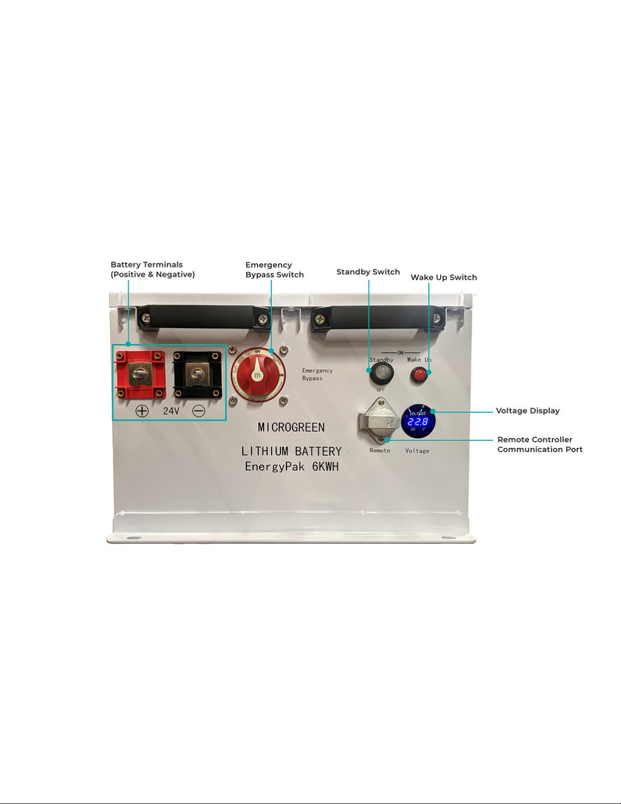
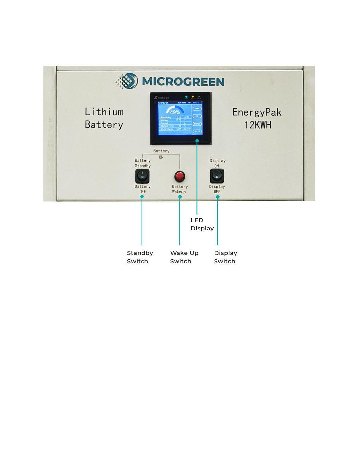
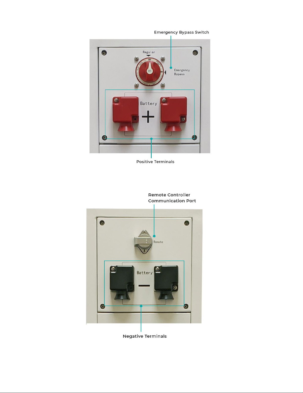
All models include a temperature sensing mechanism and an internal heater for low-temperature charging,
as well as a remote controller with a display screen to view and set the operating parameters.
NOTE: The voltages shown here are the nominal voltages rounded to standard electrical system voltages. The actual
operating voltage varies with the SOC and is normally higher at high SOC, as shown in the product specifications sheet at
the end of this manual.
Available Models of Energy Pak
Energy Pak
Model
Energy Storage
Capacity
Nominal Voltage
(approximate)
Energy Pak 3 –EP 12240
3 kWh
12 V
Energy Pak 6 –EP 12280
6 kWh
12 V
Energy Pak 6–EP 24240
6 kWh
24 V
Energy Pak 12 –EP 24480
12 kWh
24 V
Energy Pak 12 –EP 48240
12 kWh
48 V

7
The Energy Pak can be operated using the buttons and switches located directly on the front panel (see
Figure below), or using the LED Display / Remote Controller. For the Energy Pak 3 and Energy Pak 6 this is an
optional component that plugs into it (see Figure 3e below). Table 3 explains the components of the user
interface found on the Energy Pak and on the LED Display / Remote Controller.
The the LED Display / Remote Controller includes a display screen to provide battery’s operating parameters.
It is not compulsory to monitor the Display screen during normal operations of Energy Pak. Some users may
find the information provided about the operating parameters valuable. It may also provide useful insight if
any troubleshooting is required.
Figure 3a: Front panel components of the 6 kWh Energy Pak (Note: same elements available on the 3 kWh Energy Pak)

8
Figure 3b: Front Panel components of the 12 kWh Energy Pak

9
Figure 3c: Left Panel components of the 12 kWh Energy Pak
Figure 3d: Right Panel components of the 12 kWh Energy Pak

10
Table 3: Features of the Main Panel
FEATURE
DESCRIPTION
Battery Terminals
The positive and negative terminals provide the power connections needed
to transfer power to or from the Energy Pak.
Voltage Display
Shows the operating voltage of Energy Pak.
Standby Switch
When the Standby switch is in the OFF position, the Energy Pak is OFF and
no power is available from the Battery Terminals. When it is in the ON
position, the Energy Pak is in Standby mode where no power will be
available from the battery terminals until the Wake Up button is pressed
for 5 seconds.
Wake Up Button
Pressing this switch will wake up the Energy Pak. If the Standby switch is
ON, the Energy Pak will stay ON after pressing the Wake Up button for 5
seconds. If the Standby switch is OFF, the Energy Pak will be ON while the
Wake Up button is pressed, but will be OFF when the Wake Up button is
released.
Emergency Bypass Switch
This switch should be OFF at virtually all times. It is used only when the
Energy Pak’s control circuits have shut down the system, and there is an
emergency need to use the battery. When the Emergency Bypass is ON,
power is directly delivered from the batteries while bypassing all the other
switches; the BMS and protective circuitries are bypassed.
This allows the Energy Pak to provide power despite risk of
damage and personal injury. Extreme caution must be taken when using
the Emergency Bypass.
Remember to switch the Emergency Bypass switch back to the OFF
position after any emergency usage.
Communication Port (for
Remote Controller)
This port is for the user to plug in the LED Display /Remote Controller.
Display
This comes with the Energy Pak 12 ONLY, replacing the voltage display of
the Energy Pak 3 and Energy Pak 6 models. The Display is available on the
Energy Pak 3 and Energy Pak 6 as an optional wired component.
This can be used to turn the Energy Pak ON/OFF. It also displays operating
parameters:
●Energy Pak overall voltage
●Voltage of individual battery cells
●Electrical current
●Battery temperature
●Battery state of charge

11
The picture below shows the default mode of the LED display. The LED display is included in the Energy Pak
12, and is optional for the Energy Pak 3 and Energy Pak 6 via a wired connection (see Section 9 for more
details).
Figure 3e: LED display / Remote Controller

12
4Important Safety Information
WARNING
This manual contains important instructions for all Energy Pak models that must be followed during
installation, and operation. Failure to follow these instructions may result in damage, fire, injury or death.
●Do not attempt to use the Energy Pak if it appears damaged.
●Do not allow the Energy Pak to be submerged in water. It is not waterproof.
●Do not attempt to disassemble the Energy Pak. There are no user-serviceable parts inside. Coming
into contact with the electrolyte contained in the battery cells can cause personal injury.
●To avoid risk of shock or fire, make sure all wires are properly sized and prepared in good condition.
●Verify that all equipment to be connected to the Energy Pak is turned OFF before making any
connections.
●Make sure the Energy Pak is turned OFF before making connections.
●This equipment contains components which can produce electrical arcs or sparks. To prevent fire or
explosion do not install in compartments containing flammable materials or in locations which require
ignition-protected equipment. This includes any space containing gasoline-powered machinery, fuel
tanks, or joints, fittings, or other connection between components of a fuel system.
●Remove metallic personal items such as rings, bracelets, necklaces, and watches when working with a
battery. A battery can produce a short-circuit current high enough to weld a ring or other metallic items,
causing a severe burn.
●Use caution when working with metal tools near the Energy Pak. Do not short the Energy Pak by
connecting any metallic object across the positive and negative terminals. The resulting short-circuit
may cause fire, serious injury or death.
●Ensure any connected equipment is compatible with the voltage and current specifications for your
Energy Pak (see section 12: Product Specifications). If using a multi-chemistry battery charger, ensure it
is set for lithium iron phosphate (also known as LFP or LiFePO4).
WARNING –LIMITATIONS ON USE
The Energy Pak should not be used in connection with life support systems or other medical
equipment or devices.

13
5Installation
Follow any applicable regulations when installing the Energy Pak.
The Energy Pak must be turned OFF during installation. Avoid touching the battery terminals. Do not place
any objects on top of the Energy Pak. Do not sit, stand or lean on the Energy Pak.
1. Selecting your location
The Energy Pak should be installed in a dry area that is free from moisture. Do not install this product in
locations where flooding may occur. Install the Energy Pak as close as possible to the charger, inverter and/or
electrical loads to minimize power losses in the cables.
If installing on a concrete floor, it is recommended to place the Energy Pak on an insulating pad to prevent
the cold temperature of the floor from affecting battery performance.
Unlike some types of AGM batteries, ventilation is not required. The Energy Pak does not discharge toxic
chemicals or vapours.
Do not install in compartments containing flammable materials or in locations which require ignition-
protected equipment. This includes any space containing gasoline-powered machinery, fuel tanks, or joints,
fittings, or other connection between components of a fuel system.
2. Proper orientation
It is best to place the Energy Pak in the upright position, i.e. with all labels oriented horizontally. Placing the
Energy Pak on its side is permitted but not recommended. Never place the Energy Pak upside down - this
could lead to the battery cells detaching from the bottom of the chassis, which can then lead to short circuits.
Secure the Energy Pak with fasteners after installation, especially if it is being used in a moving vehicle such as
a boat or RV. This is especially applicable to the Energy Pak 3 and Energy Pak 6; note that the casing contains
holes which enable them to be fastened down with screws; use screws of an appropriate strength and fasten
them to fixtures capable of supporting the weight.

14
3. Wiring:
Whenever making any connection to the battery terminals, DOUBLE-CHECK that the polarity is correct.
Do not connect more than one pair of electrical cables to the battery terminals of the Energy Pak. If you want
to power multiple loads, use two bus bars that each make a single connection to one of the battery terminals
of the Energy Pak, and then connect all of your loads to the bus bars. Attempting to stack multiple cables
from multiple loads onto the Battery Terminals can cause excessive strain and potentially damage the
terminals. See Figure 5a below for proper usage of a bus bar for multiple loads. Figure 5b shows a frequently
encountered incorrect connection that should be avoided.
Figure 5a: Correct connection for multiple loads using bus bars

15
Figure 5b: Incorrect connection for multiple loads (multiple wires directly connected to the battery terminal)
4. Use power cables with proper gauge
Users are advised to select the proper length and specifications of power cables to fit the power rating of their
applications. The Energy Pak has been designed to handle a maximum current of 250A. The required cable
specifications for different current ratings are listed below. The size of the cable will also vary depending on
the length of the cable run. Consult with an electrician to ensure the cable is sized according to the electrical
code within your region.
Undersizing the power cables can potentially cause a risk of equipment damage or personal injury.
It is recommended that at least 2 people are present during the installation. This is a common
safety practice when working with electrical equipment in case of electrocution. The weight of the Energy
Pak (33 kg - 115 kg depending on model) cannot be readily handled by one person.
Once the power cables have been connected to the Energy Pak and to the load, it is ready for use.

16
6Normal Operation
Once installed, you can operate the Energy Pak simply by turning it on/off. It must be turned on to supply
power or to charge. The Energy Pak should be turned off during installation, when connecting/disconnecting
wires, and for long-term storage.
To turn ON the Energy Pak for charge & discharge (regular) operation
1. Turn the Standby switch to the ON position
2. Press and hold the Wake Up button for approximately 5 seconds. Release the button after a click
sound is heard.
3. The Energy Pak is now turned on and can be used for normal charge and discharge operations. This
can be confirmed by checking that the Voltage Display has illuminated.
To turn OFF the Energy Pak for disconnecting & storing
1. Turn the Standby switch to the OFF position.
2. The Energy Pak is now turned off. This can be confirmed by checking that the Voltage Display is no
longer illuminated.
Charging your Energy Pak
You can charge the Energy Pak by connecting a power source to the battery terminals. Some common
sources of charging power are listed below. In each case, connect your power source to a charger, then
connect the outputs of your charger to the battery terminals on the front panel of the Energy Pak.
•Grid power connected to a charger
•Solar panels connected to a charge controller
•Vehicle alternator or boat alternator connected to a charger
•Wind turbine or hydro turbine connected to a charger
DO NOT OVERLOAD your Energy Pak
Always operate your Energy Pak within the permitted current limit to prevent overload. When overloading
occurs, the Energy Pak will automatically shut down as a safety precaution, and will have to go through a
restart procedure. The current limit for all models is 250 A.

17
Maintain the SOC level above 20% to avoid auto-shutdown
The built-in BMS has been programmed to shut off the Energy Pak when the SOC (State of Charge) falls below
approximately 20%. This prevents over-discharging the battery cells and improves the operating lifetime of
your Energy Pak.
To avoid auto-shutdown, keep the SOC above 20% at all times. See the table below to see how the voltage
corresponds to the SOC. In practice, it may be best to start charging Energy Pak at an SOC of 30% to provide a
safety margin.
BATTERY VOLTAGE V ( no load attached )
12 V Model
24 V Model
48 V Model
SOC %
12.4
24.8
49.6
20
12.6
25.2
50.4
30
12.8
25.6
51.2
40
13
26
52
50
13.2
26.4
52.8
60
13.4
26.8
53.6
70
13.6
27.2
54.4
80
13.8
27.6
55.2
90
14.4
28.8
57.6
100
Table 6: Battery Voltage vs. SOC. Note: SOC % is approximate due to the variability of battery cells.
Note that the shutting down of the Energy Pak at 20% SOC means that 80% of the capacity is still utilized for
powering your loads. By comparison, only 50% of the capacity for AGM and flooded batteries can typically be
used for powering your loads.
Initializing Phase
Due to the chemistry of lithium ion battery cells, the Energy Pak reaches its maximum energy capacity after
about 10 full charge-discharge cycles.

18
In addition, if you have an LED display, the SOC indicator may not be accurate until 1 full charge-discharge
cycle has occurred. Furthermore, the SOC may become inaccurate over time; again, a full charge-discharge
cycle will restore the accuracy of the indicator.
Low Temperature Operation
Due to the inherent nature of lithium ion battery cells, their performance is reduced at low temperatures. The
Energy Pak can provide power in temperatures down to -30°C, but its efficiency will be significantly lower
compared to room temperature operation.
It is not safe to charge lithium ion batteries below 0°C. The Energy Pak includes a temperature sensor and an
internal heater to permit charging at low temperatures. When charging at temperatures below 0°C, the
Energy Pak will heat its batteries to 0°C before charging. You likely would encounter a delay from the time a
power source is connected to the time the Energy Pak begins storing energy while it heats up.
Monitor Operating Conditions for the best user experience
The Energy Pak features a BMS (Battery Management System) which includes circuitry that continuously
monitors and protects the battery from overcharging, overdischarging, or overheating. It will automatically
shut down the Energy Pak if it approaches an unsafe state. Although this will protect the battery, a restart
procedure will have to be performed before using the Energy Pak again. It is best to avoid having the BMS
shut down the system. Therefore it is advisable to monitor the following operating parameters when using the
Energy Pak. The LED display / remote controller (see Section 9) will allow you to monitor all of these
parameters. See Section 5 also for a description of the restart procedure.
1. SOC (State of Charge): indicates how much energy is in the Energy Pak, i.e. how full the battery is, at any
time; use this to estimate how much runtime the battery has left, and to avoid overdischarging and
ending up with a dead battery.
2. Voltage: another indication of how much energy is in the Energy Pak (the SOC is derived from voltage
measurements); use this to estimate how much runtime the battery has left, and to avoid overdischarging
and ending up with a dead battery. If you do not have an LED display; rely on the voltage display to
estimate the SOC.
3. Current: indicates how much electrical current, and by extension how much power, is being consumed or
supplied; use this to determine whether the battery is close to being overloaded.
4. Temperature: The efficiency of Energy Pak has a critical dependency on the operating temperature. The
ideal operation temperature is betweeen 5°C and 30°C. The Energy Pak will shut itself down if the
temperature goes below -20°C or above 68°C.

19
7Maintenance / Protections and Storage
7.1 Maintenance / Protections
Unlike traditional AGM batteries, the Energy Pak can be operated safely with little maintenance.
The Energy Pak features a BMS (Battery Management System) which is a protective circuitry that
continuously monitors and protects the battery from being overcharged, overdrained, or
overheated. It will automatically shut down the Energy Pak (system) if any improper state is reached.
Also, the Energy Pak has a built-in heating system which will heat the battery whenever there is a
need to charge the battery when its temperature is below 0°C.
Although the BMS will protect the battery, it is best to avoid having it shutdown the system, as a
restart procedure will have to be performed. Therefore it is advised to monitor the state of
operation of the Energy Pak as you are using it. See Section 6 for the operating attributes to monitor
and the significance of them.
7.2 Off-season Storage Procedure
●Turn the Energy Pak OFF for long term storage (>1 week) to avoid draining the battery.
●Although the Energy Pak has a very low self discharge rate when OFF (≤2%/month, ≤12%/year), it should
be charged a minimum of once every six months.
●Recommended state of charge for long-term storage: 50%
●Recommended storage temperature: 15°C to 35°C.
●Warranty-approved storage temperature: -30°C to 45°C
●Recommended storage humidity: 45% to 75%relative humidity.
Note: it is NOT necessary to disconnect the battery terminals during storage; turning the Energy Pak off
automatically disengages the battery from the terminals.
This manual suits for next models
7
Table of contents