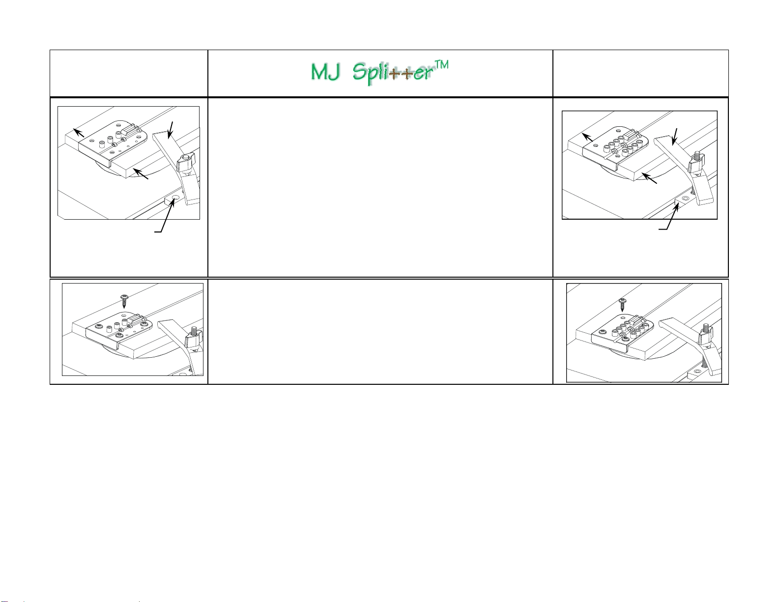
5
Model SP-0125
1/8” Kerf Splitter - Green
Follow drawings under here Ð
Model SP-0100TK
Thin Kerf Splitter - Yellow
Follow drawings under here Ð
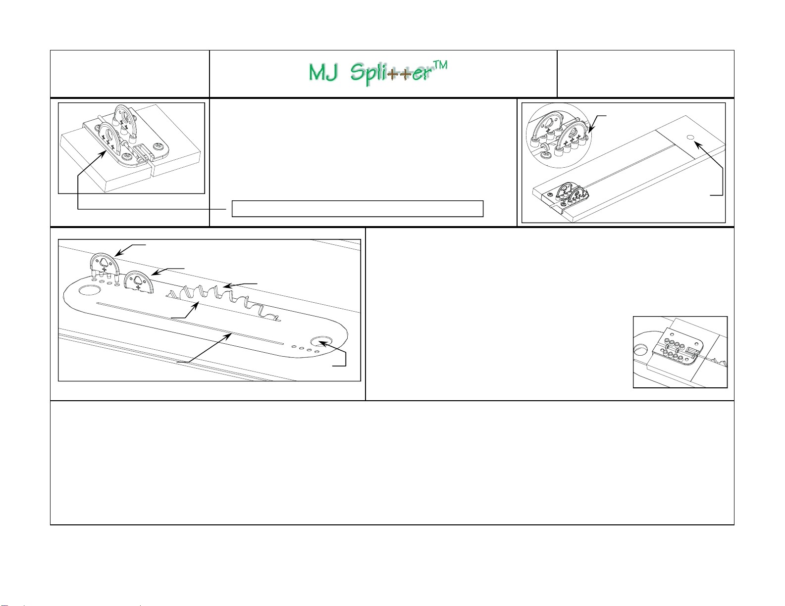
Drill a through
hole to hang
No drilling required
for storage
Step 9
Store both MJ Splitters and the drill bit in the Drill Guide (drill through the
first two tabs at the drill bit storage channel). Shorten the MDF Setup
Board for easy storage as shown on left. The cut away portion of the
Setup Board can be used as a puller with a finger-pressure squeeze from
both sides to remove the MJ Splitter from the mounting holes.
Alternatively, drill a through hole on the Setup Board to hang as shown on
the right for reuse on the next ZCI.
Drill through MDF for splitter storage. SP-0125 Green model only.
Position of splitter with saw blade fully raised.
These holes are for illustrative purposes only.
Position of splitter with saw blade at 1” height.
Saw blade at 1” height.
Long Saw Kerf with fully
raised saw blade.
Short Saw Kerf with saw
blade at 1” height.
7/8” Finger Pull Hole
Double Kerf Bonus Trick: Some table saws allow you to rotate the ZCI from end to
end. The MJ Splitter brings valuable advantages to this feature. Now you can create two
kerfs on the same plastic or wood ZCI as shown in the drawing on the left. One kerf is cre-
ated with saw blade fully raised for thick stock, and the other with the shorter kerf is for use
with the saw blade at 1” height for 3/4” stock. In this case, install the MJ Splitter about
1 1/2” closer to the saw blade. In order to properly install the MJ Splitter for the 1” height
kerf, in Step 3, draw a line on the Setup Board that is 1/2” from the Drill Guide and align the
first carbide tooth flush with top of the Setup Board and the 1/2”
line, and then proceed to Step 4. Similarly, you can also create
one kerf for a 1/8” saw blade and the other for a thin kerf
blade. Only use the MJ Splitter designated for the thickness
of your saw blades! Make sure the ZCI has a snug fit in the
opening prior to installation. There is also a handy trick for easily
creating the kerf on the ZCI shown in the GRR-Ripper® DVD (sold
separately).
Important: All Micro Jig products are designed to increase both safety and accuracy in woodworking. Thus, an additional feature of the MJ Splitter is that it serves as
a warning device when wood is not suitable for cutting on the table saw, or when your technique is inherently unsafe. Cutting wood with internal stress on the table saw
can often lead to bodily injury as well as damage to equipment regardless of the type of safety devices in use. While closing or twisting behind the saw blade, wood
with a great amount of internal stress may grab both sides of the MJ Splitter and pull it out of its mounting holes. Unsafe cutting technique can also pull the MJ Splitter
from the ZCI, e.g., improper feeding with no downward pressure can cause the wood to lift off the table saw surface, and excessive feeding pressure from the off-cut
side toward the fence can cause the wood to pinch the MJ Splitter. Although the MJ Splitter will act as a “kerf keeper” if it is pulled out of its mounting holes during a
cutting operation – you must consider this event a warning signal! Turn off the table saw immediately to avoid personal injury and damage to equipment due to
uncontrollable wood movement, and take the appropriate corrective action before proceeding. The use of the standard kerf green MJ Splitter (SP-0125) with a Thin
Kerf blade may also cause the MJ Splitter to pop out. Using a Thin Kerf Yellow MJ Splitter (SP-0100TK) with a 1/8” saw blade may leave too much of a gap, which will
lessen its effectiveness. Be sure to choose the MJ Splitter designed for the thickness of your saw blade in present use!