Micromagic systems MSR-H01 User manual


Safety First!
Updated: 18-Aug-2008
Safety First!
Read and understand the documentation associated with any of the tools used in the assembly
of these kits. Work in a clean, well-lit environment. Work slowly taking breaks often. Plan your
work with plenty of extra time to avoid cramming to complete the project at the last minute.
micromagic systems has taken every step to ensure the products sold are safe when used in a
responsible manner. Therefore, micromagic systems cannot be held accountable for
irresponsible, careless or reckless behavior of the builder.
These kits are purely educational. Items sold by micromagic systems are not authorized for
use in human contact, medical, life-saving, life-support, industrial or light industrial
applications. Do not under any circumstances use these robots to move, touch, or handle
dangerous or hazardous materials. Doing this could result in injury or death to the user, or
damage to property.
Please note that Robots can move without warning, wear eye protection at all times
and never touch a powered robot!
micromagic systems is not responsible for any special, incidental, or consequential damages
resulting from any breach of warranty, or under any legal theory, including lost profits,
downtime, goodwill, damage to or replacement of equipment or property, and any costs of
recovering, reprogramming, or reproducing of data associated with the use of the mechanics,
hardware or software it sells
Battery Advise
NiCd, NiMh, LiPo & LiIo batteries store a great amount of energy and can damage equipment
or cause fire if shorted and an improper fuse is installed or bypassed. Always use an inline fuse
with your battery pack. Disconnect all batteries when not in use. Store in a cool dry place. Use
only the manufacturers recommended charging equipment for your batteries.
Acrylic Parts

Hitec Servo Preparation Guide
Updated: 18-Aug-2008
Before attaching servos to your robot, it is necessary to
check that the servo horn is fitted correctly and in the
center position. This guide will explain how this is achieved.
Print this single page document with the following settings:
Paper A4 or Letter, Margins 0.4", Scale 70%. tested in IE7
& Firefox 3.0.1
Index
Servo Horn Position
Servo Horn Centering
Servo Horn Position
Figure 1.
When you first remove your Hitec servo
from the packet, the servo horn should be
fitted in the position shown in Figure 1. This
should be the servo center position,
however, this is not guaranteed so we
suggest this is checked before you begin kit
assembly. (See Setting Servo Center)
The holes indicated by (A) & (B) are used
for attaching the horn to other mechanical
assemblies. This is done with No.2 self
tapping screws. Although not necessary,
you may wish to open these holes up with a
1.5mm or 1/16" drill for easier assembly.
Hitec servo splines have 24 teeth, which
means the servo horn can be moved
around in 15° increments.
Servo Horn Centering To check if your servo horn has been fitted
in the mid position (center of rotation)
correctly as shown in Figure 1. you will
need to power up the servo with a 1.5ms
positive pulse sent every 20ms (50Hz). This
can be done using an R/C style transmitter/
receiver, a p.Brain-HexEngine or SSC.
Using p.Brain-HexEngine
Connect a 6.0V power supply or battery
pack via a switch to the SMB board, V+ to
the VS screw terminal and V- to one of the
GND screw terminals. Install a jumper on
JP3 across pins 1-2, this sets VL = VS for
single power source supply. Remove any
jumpers on CN18. Connect the terminal
port RJ11 4/4 connector to the serial port of
your host computer using a suitable lead
such as a p.Brain-RJ232.

p.Brain-hexEngine: 6V dc is supplied to the VS terminal via
a switch, with JP3 1-2 link in place to supply VL from VS. Open up a connection in your terminal
software on the host system, set the baud
to match that of your HexEngine ( default =
115200,N,8,1). Switch on power to the
SMB, you should see a RED led near the
terminal block illuminate (if it does not,
switch off power immediately and check
your circuit). When powered up you should
see the HexEngine display message in the
terminal window, enter the SERVO TEST
screen by typing "SERVO TEST" within your
terminal screen. Once in SERVO TEST
mode, select the servo you wish to test
using the left/right cursor keys, press the
'2' key to send the servo to the required
1.5ms mid position. The servo horn should
now be in the position indicated by Figure
1.
Using Lynxmotion SSC32
Please visit the following link: http://www.
lynxmotion.com/images/html/build046.htm
Once you have your servo powered up with
the required 1.5ms signal, If you find your
servo horn is not in the expected position
remove the servo horn and move it as close
to the position indicated in Figure 1.

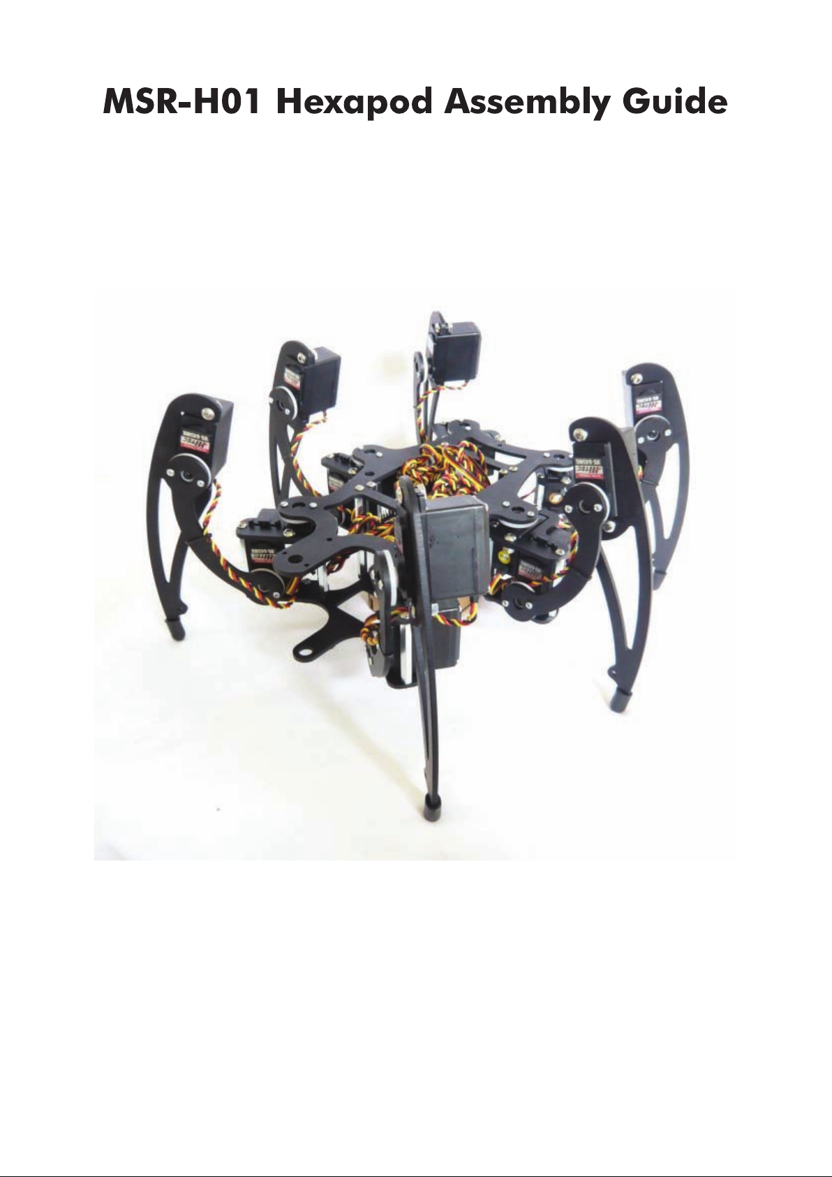
MSR-H01 Hexapod Assembly Guide
Updated: 18-Aug-2008
Read first: Safety First!
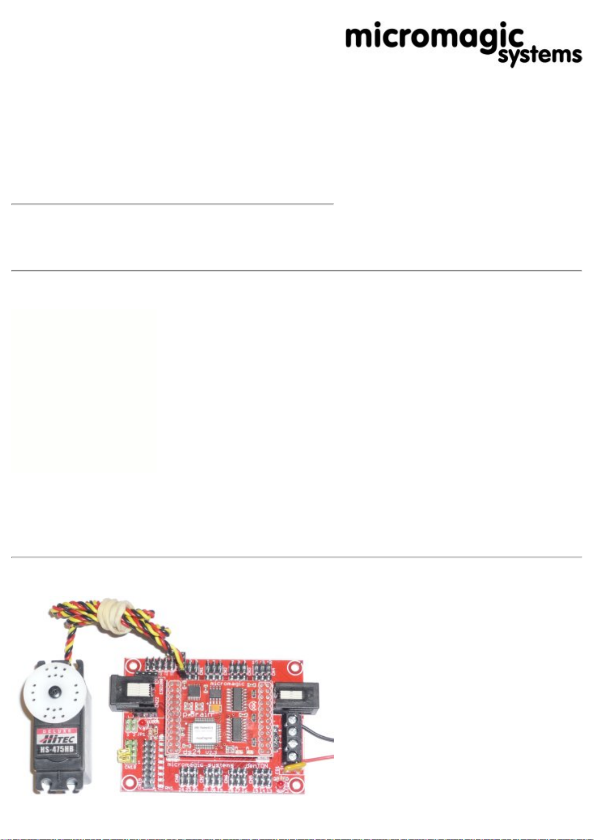
Read first: Servo Preparation Guide
Properly identify all screws, washers, stand-offs and
hardware etc. and gather together those necessary for
each step. Carefully read and study the drawings prior to
each assembly.
Print this 6 page document with the following settings:
Paper A4 or Letter, Margins 0.4", Scale 66%. tested in
IE7 & Firefox 3.0.1
Index
Coxa Bottom Plate Assembly MSR-H01_ASSY01
Coxa Top Plate Assembly MSR-H01_ASSY02
Coxa Top Plate & Servo Assembly MSR-H01_ASSY03
Coxa & Femur Servo Assembly MSR-H01-ASSY04
Tibia Plate & Servo Assembly MSR-H01-ASSY05
Right Leg Finish Assembly MSR-H01-ASSY06
Left Leg Assembly MSR-H01-ASSY07
Lower Body Assembly MSR-H01-ASSY08
Upper Body Assembly MSR-H01-ASSY09
p.Brain-SMB Circuit Board Installation
Leg & Body Attachment Assembly MSR-H01-ASSY10
Lower Body Attachment Assembly MSR-H01-ASSY11
Appendix A - Assembly Hardware
Appendix B - Aluminum Leg Parts
Appendix C - Aluminum Body Parts
MSR-H01 Right Leg Assembly
Coxa Bottom Plate
Assembly MSR-H01_ASSY01 Parts List
ITEM QTY PART NUMBER DESCRIPTION
1 1 MSR-H01-COXA02 MSR-H01 Coxa Bottom Plate
2 1 MSR-P004 M3 x 16 Hexagon Socket Button Head
3 1 MSR-P013 M3 Hex Full Nut
4 1 MSR-P005 9 x 6mm Round Zinc Plated Brass Spacer
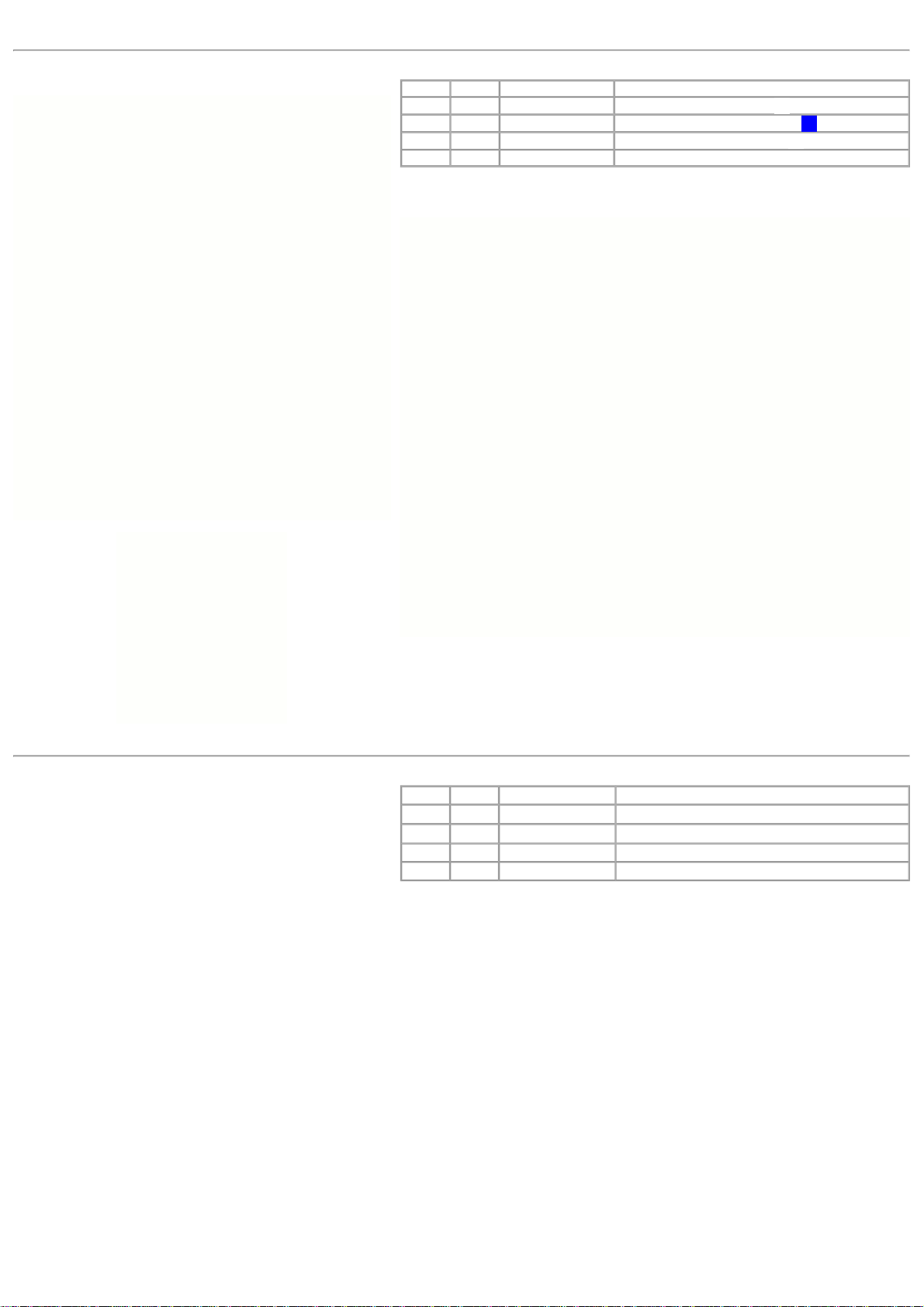
Assemble as per diagram, pay attention to coxa bottom plate orientation.
Coxa Top Plate
Assembly MSR-H01_ASSY02 Parts List
ITEM QTY PART NUMBER DESCRIPTION
1 1 MSR-H01-COXA01 MSR-H01 Coxa Top Plate
2 2 MSR-P001 M3 x 40mm F-F Steel Hexagonal Spacer
3 2 MSR-P007 M3 x 10 Hexagon Socket Button Head
4 2 MSR-P014 M3 Plain Washer
Assemble as per diagram, pay attention of coxa top plate orientation.
When using HS-645MG servos for the femur joint, the M3 washer part (4) must be
fitted. If using 40mm standard case size servos such as HS-985MG, do not fit part
(4).

Coxa Top Plate & Servo
Assembly MSR-H01_ASSY03
Parts List
ITEM QTY PART NUMBER DESCRIPTION
1 1 MSR-H01-ASSY02 MSR-H01 Coxa Assembly
2 2 MSR-P006 M4 x 10 Hexagon Socket Button Head
3 2 MSR-P012 M4 Hex Full Nut
4 1 MSR-HS225BB/MG Hitec HS-225BB or HS-225MG Servo
5 1 MSR-HSH24 Hitec 24mm Servo horn (from HS-225 servo)
6 1 MSR-HSSST Hitec Servo horn screw (from HS-225 servo)
The servo horn (5) must be removed in order to fit the coxa servo (4). Take care
not to rotate the servo spline when unscrewing the horn retaining screw (6).
After the servo (4) has been fitted, replace the horn (5) in the same position.
Having re-fitted your servo horn, I strongly recommend that you re-check your
coxa servo is still centered: Servo Preparation Guide
Pay attention to the servo orientation, the servo horn is at the end closest to the
hexagonal spacers.
Coxa & Femur Servo
Assembly MSR-H01-ASSY04
Parts List
ITEM QTY PART NUMBER DESCRIPTION
1 1 MSR-H01-ASSY01 MSR-H01 Coxa assembly
2 2 MSR-P007 M3 x 10 Hexagon Socket Button Head
3 1 MSR-H01-ASSY02 MSR-H01 Coxa assembly
4 1 MSR-HS645MG Hitec HS-645MG Servo
Insert the femur servo (4) into the top coxa plate slot as shown with the servo
horn towards the bottom coxa plate.
Tibia Plate & Servo
Assembly MSR-H01-ASSY05
Parts List
ITEM QTY PART NUMBER DESCRIPTION
1 1 MSR-H01-TIBIA MSR-H01 Tibia plate
2 2 MSR-P006 M4 x 10 Hexagon Socket Button Head
3 2 MSR-P012 M4 Hex Full Nut
4 1 HS-645MG Hitec HS-645MG Servo
Assemble as per diagram, pay attention to the servo orientation, the servo horn
is closest to the foot of the tibia.

Right Leg Finish
Assembly MSR-H01-ASSY06
Parts List
ITEM QTY PART NUMBER DESCRIPTION
1 1 MSR-H01-ASSY04 MSR-H01 Coxa assembly
2 1 MSR-H01-FEMUR MDR-H01 Femur plate
3 4 MSR-P008 N0.2 x 6.4mm Self tapping screw
4 1 MSR-H01-ASSY05 MSR-H01 Tibia assembly
Take great care when fitting self tapping screws (3). Use the correct size
phillips screw driver to avoid slipping or damaging the screw head. Once fitted
the servo horn should fit flush with the femur plate, if this is not the case, back
the screws (3) off a couple of turns and then re-tighten. Fit the screws into the
middle of the single row of three holes on the horn indicated below (A) & (B).
Although not necessary, the servo horn screw holes can be enlarged using a
1.5mm or 1/16" drill bit for easier screw installation.
You will need to build three right legs for your hexapod, so repeat steps 1 to 6
until all right legs are complete.
MSR-H01 Left Leg Assembly
Left Leg
Assembly MSR-H01-ASSY07
You will need to assemble three left legs for your hexapod. As for the right leg,
follow steps 1 to 6, however, build the left leg as a mirror of the right leg
assembly. To ensure you get your coxa plate orientation correct, take a good look
at the left leg pictures below and left.

MSR-H01 Body Plate Assemblies
Lower Body
Assembly MSR-H01-ASSY08
Parts List
ITEM QTY PART NUMBER DESCRIPTION
1 1 MSR-H01-BODY02 MSR-H01 Lower Body Plate
2 6 MSR-P011 M6 x 4mm Insulation Washer
3 4 MSR-P010 12 x 3.5mm Stick-on Rubber Bumper
First insert the insulation washers (2) into the lower body plate, you may find
these should insert easier on one side of the body. Now turn the body over and
mount the stick-on rubber bumpers in locations shown below.
Upper Body
Assembly MSR-H01-ASSY09 Parts List
ITEM QTY PART NUMBER DESCRIPTION
1 1 MSR-H01-BODY01 MSR-H01 Upper Body Plate
2 4 MSR-P003 M3 x 60mm F-F Steel Hex Spacer
3 4 MSR-P002 M3 x 30mm F-F Nylon hex Spacer
4 8 MSR-P007 M3 x 10mm Hexagon Socket Button Head
Assemble the upper body plate as per the diagram to the left, if required move to
(9b) to fit the optional p.Brain-SMB circuit board.
p.Brain-SMB Circuit Board Installation
Parts List
ITEM QTY PART NUMBER DESCRIPTION
1 1 MSR-H01-ASSY10 MSR-H01 Assembly
2 4 MSR-P007 M3 x 10mm Hexagon Socket Button Head
3 1 p.Brain-SMB p.Brain-SMB Circuit Board
Fit the p.Brain-SMB as shown in the diagram, if you have a battery switch
harness, its a good idea to fit it now.

MSR-H01 Final Assembly
Leg & Body Attachment
Assembly MSR-H01-ASSY10
Parts List
ITEM QTY PART NUMBER DESCRIPTION
1 1 MSR-H01-ASSY09 MSR-H01 Body Assembly
2 3 MSR-H01-ASSY06 MSR-H01 Right Leg Assembly
3 3 MSR-H01-ASSY07 MSR-H01Left Leg Assembly
4 12 MSR-P008 N0.2 x 6.4mm Self tapping screw
Attach right and left legs as shown in the diagram below and exploded detail left.
Take great care when fitting self tapping screws (3). Use the correct size
phillips screw driver to avoid slipping or damaging the screw head. Once fitted
the servo horn should fit flush with the femur plate, if this is not the case, back
the screws (3) off a couple of turns and then re-tighten. Fit the screws into the
middle of the single row of three holes on the horn indicated left (A) & (B).
Lower & Upper Body Attachment
Assembly MSR-H01-ASSY11 Parts List
ITEM QTY PART NUMBER DESCRIPTION
1 1 MSR-H01-ASSY11 MSR-H01 Assembly
2 1 MSR-H01-ASSY09 MSR-H01 Lower Body Assembly
3 4 MSR-P007 M3 x 10mm Hexagon Socket Button Head
4 6 MSR-P009 Rubber End Cap M5 x 13mm
Slide the bottom plate assembly (2) over the coxa bearings and fix in place. Add
rubber end caps (4) to tarsus feet. This completes the MSR-H01 assembly.

You now need to spend some time carefully routing the servo cables back to the
control electronics. The way in which the cables are routed very much depends
on the electronics used and personal preference. You may use small cable ties or
expandable cable sleeving to tidy servo leads. When you have routed and cable
tied the servo leads, make sure the legs have room to rotate through their
operational range without pulling or pinching any cables.

Appendices
Appendix A
Assembly Hardware Assembly Hardware Parts List
ITEM QTY PART NUMBER DESCRIPTION
1 12 MSR-P001 M3 x 40mm F-F Steel Hexagonal Spacer
2 4 MSR-P002 M3 x 30mm F-F Nylon hex Spacer
3 4 MSR-P003 M3 x 60mm F-F Steel Hex Spacer
4 6 MSR-P005 9 x 6mm BZP Brass Round Spacer
5 6 MSR-P011 M6 x 4mm Nylon Insulation Washer
6 6 MSR-P004 M3 x 16mm Stainless Steel Hexagon Socket
Button Head
7 42 MSR-P007 M3 x 10mm Stainless Steel Hexagon Socket
Button Head
8 25 MSR-P006 M4 x 10mm Stainless Steel Hexagon Socket
Button Head
9 38 MSR-P008 N0.2 x 6.5mm BZP Steel Self tapping screw
10 7 MSR-P013 M3 BZP Steel Hex Full Nut
11 25 MSR-P012 M4 BZP Steel Hex Full Nut
12 14 MSR-P014 M3 BZP Steel Plain Washer
13 4 MSR-P010 12 x 3.5mm Stick-on Rubber Bumper
14 6 MSR-P009 M5 x 13mm Rubber End Cap
Appendix B
Aluminum Leg Parts Aluminum Leg Parts List
ITEM QTY PART NUMBER DESCRIPTION
1 6 MSR-H01-COXA01 MSR-H01 Coxa Top Plate
2 6 MSR-H01-COXA02 MSR-H01 Coxa Bottom Plate
3 6 MSR-H01-FEMUR MSR-H01 Femur
4 6 MSR-H01-TIBIA MSR-H01 Tibia
Appendix C
Aluminum Body Parts Aluminum Body Parts List
ITEM QTY PART NUMBER DESCRIPTION
1 1 MSR-H01-BODY01 MSR-H01 Body Upper Plate
2 1 MSR-H01-BODY02 MSR-H01 Body Lower Plate
Table of contents
Popular Toy manuals by other brands

Black Horce Model
Black Horce Model BH64. Instruction manual book

MTHTrains
MTHTrains Premier SD40-2 Diesel Engine Operator's manual

marklin
marklin 29490 user manual

Mattel
Mattel Disney Pixar Cars GTK91 instructions

Mega Bloks
Mega Bloks HALO 97216 manual

Fisher-Price
Fisher-Price Alpha Bus quick start guide

Eduard
Eduard Brassin MiG-19 wheels quick start guide

Seagull Models
Seagull Models HARMON ROCKET III Assembly manual

REVELL
REVELL Junkers Ju 87D Stuka quick start guide

Nexa
Nexa MITSUBISHI A6M5 ZERO Building instructions

LEGO
LEGO MIXELS MELTUS 41530 manual

Eduard
Eduard F-8E/J wing central section quick start guide