Micronor sensor MR660 Series User manual

© COPYRIGHT 2022, MICRONOR SENSORS INC.
VENTURA, CA, USA
MR660 Series
Multiaxis Fiber Optic Acceleration Sensor
System
Instruction Manual
Document: 98-0660-02
Revision: A
For Authorized Sales & Support in North America:
MICRONOR SENSORS, INC.
2085 Sperry Ave, Suite A-1
Ventura, CA 93003 USA
+1-805-389-6600
sales@micronor.com
www.micronor.com
Manufacturer and Worldwide Sales & Support:
MICRONOR AG
Pumpwerkstrasse 32
CH-8105 Regensdorf
Switzerland
+41-44-843-4020
sales@micronor.ch
www.micronor.ch
Notice of Proprietary Rights
The design concepts and engineering details embodied in this manual, which are the property of MICRONOR AG
and MICRONOR SENSORS, are to be maintained in strict confidence; no element or detail of this manual is to be
spuriously used, nor disclosed, without the express written permission of either MICRONOR AG or MICRONOR
SENSORS. entity. All rights are reserved. No part of this publication may be reproduced, stored in a retrieval system,
or transmitted in any form or by any means, electronic, mechanical, photocopying, recording, or otherwise, without
prior written permission from MICRONOR AG or MICRONOR SENSORS.

MICRONOR SENSORS MR660 Series FO Acceleration Sensor System
Page 2 of 21
Revision History
REV
Date
Technical
Representative
Notes
A
10/26/2022
DNH
Original Release

MICRONOR SENSORS MR660 Series FO Acceleration Sensor System
Page 3 of 21
Table of Contents
Revision History ...........................................................................................................2
1. Product Description ............................................................................................. 5
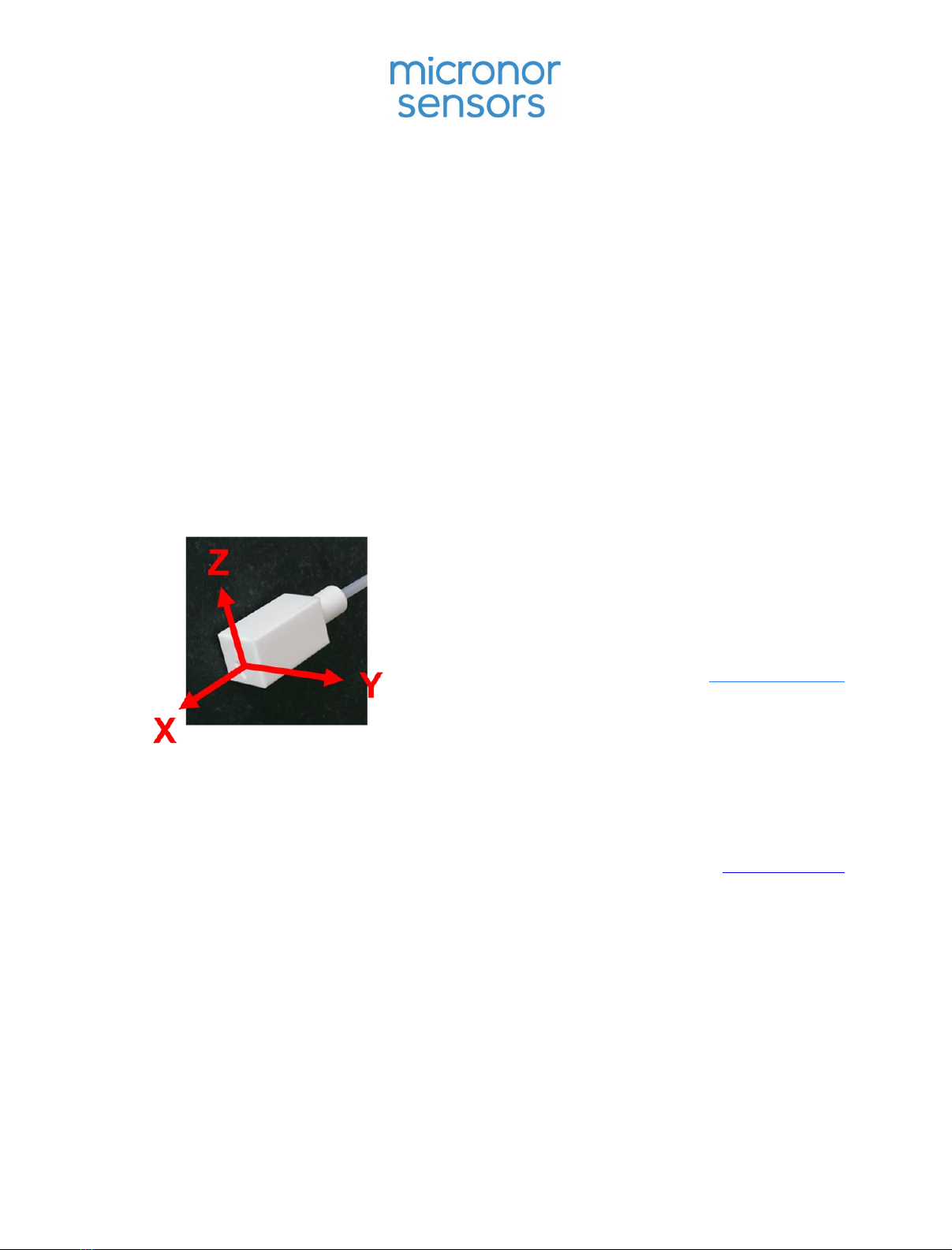
1.1 MR660 Fiber Optic Acceleration Sensor Product Family................................ 5
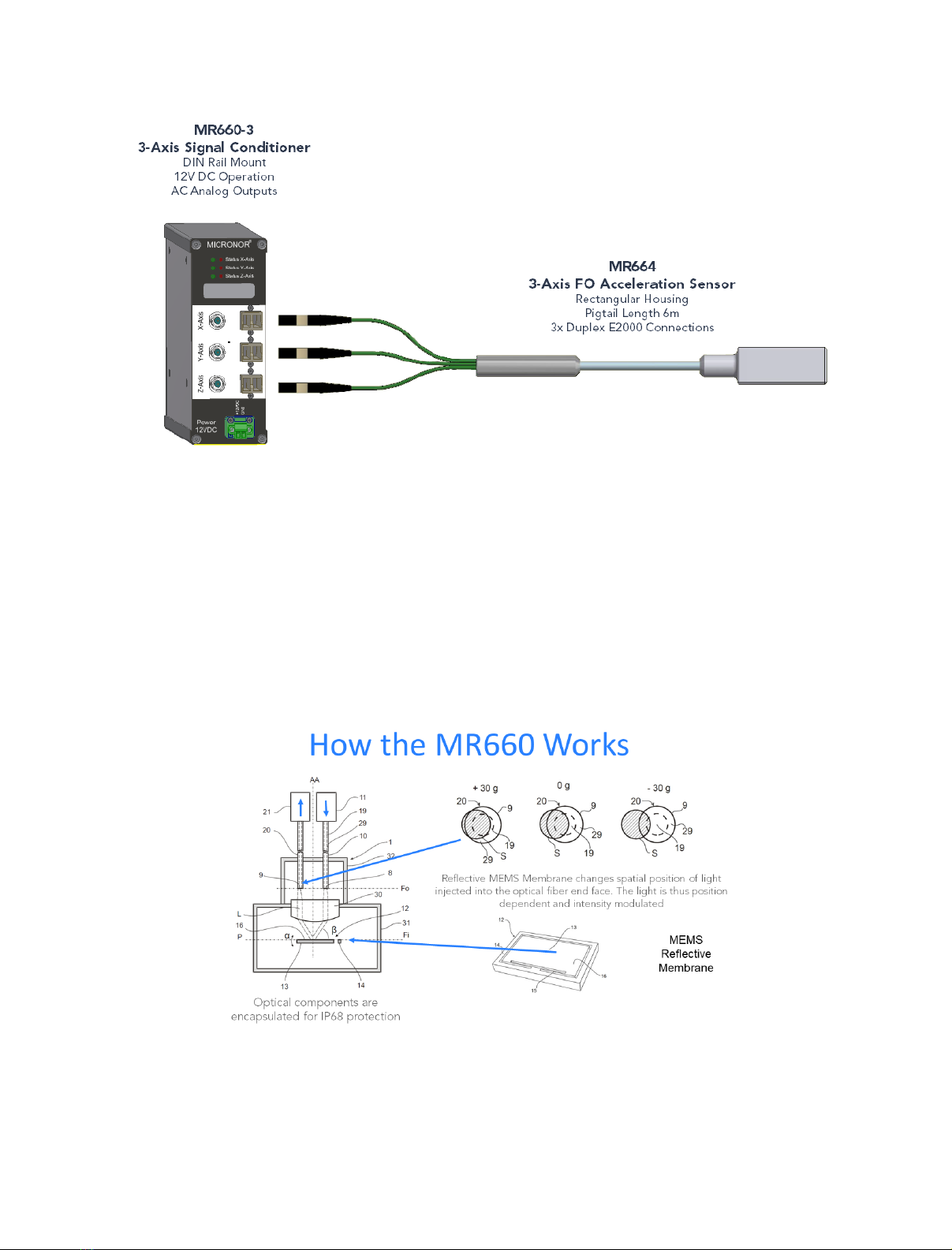
1.2 How the MR660 FO Acceleration Sensor Works ............................................ 7
2. Initial Preparation .................................................................................................9
2.1 Unpacking and Inspection ............................................................................. 9
2.2 Damage in Shipment ..................................................................................... 9
2.3 Standard Contents......................................................................................... 9
2.4 Warranty Information ...................................................................................10
3. Installation and Operation.................................................................................. 11
3.1 Mounting the Sensor Unit............................................................................ 11
3.2 Mounting Signal Conditioner Module.......................................................... 12
3.3 Sensor Optical Connection to the Signal Condition..................................... 14
3.4 Electrical Connections to Signal Conditioner............................................... 14
4. Specifications ..................................................................................................... 15
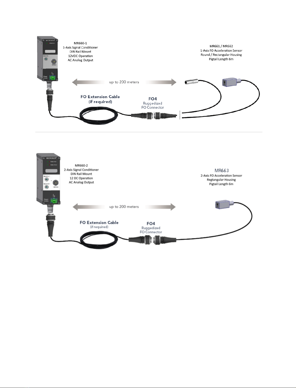
4.1 1-Axis System (MR660-1 Signal Conditioner + MR661/MR662 Sensor)........ 15
4.2 2-Axis System (MR660-2 Signal Conditioner + MR663 Sensor) .................... 16
4.3 3-Axis System (MR660-3 Signal Conditioner + MR664 Sensor) .................... 17
4.4 Response Curves ......................................................................................... 18
5. Mechanical Reference Drawings......................................................................... 19
5.1 MR660-1 1-Axis Signal Conditioner ............................................................. 19
5.2 MR660-2 2-Axis Signal Conditioner ............................................................. 19
5.3 MR660-3 3-Axis Signal Conditioner ............................................................. 19
5.4 MR661 1-Axis Round Sensor........................................................................ 20
5.5 MR662 1-Axis Rectangular Sensor ............................................................... 20
5.6 MR663 2-Axis Rectangular Sensor ............................................................... 21
5.7 MR664 3-Axis Rectangular Sensor ............................................................... 21

MICRONOR SENSORS MR660 Series FO Acceleration Sensor System
Page 4 of 21
Figures
Figure 1. MR660 Series Fiber Optic Acceleration Sensor – Available in 1/2/3 Axis ..... 5
Figure 2. MR660 1-Axis Sensor System – Signal Conditioner + Sensor....................... 6
Figure 3. MR660 2-Axis Sensor System – Signal Conditioner + Sensor....................... 6
Figure 4. MR660 3-Axis Sensor System – Signal Condtioner + Sensor........................ 7
Figure 5. How the MR660 MEMS based Acceleration Sensor Works .......................... 7
Figure 6. Block Diagram of the MR660 Signal Conditioner per Axis ........................... 8
Figure 7. Example of Rectangular MR662 Sensor epoxied to DUT ........................... 11
Figure 8. Example of Round MR661 Sensor mechanically secured to DUT ............... 11
Figure 9. Mounting Signal Conditioner to 35mm DIN Rail........................................ 12
Figure 10. Electrical and Optical Connections to the Signal Conditioners ................ 13
Figure 11. Typical Sensor Linearity over acceleration range at different frequencies 18
Figure 12. Typical Frequency Response.................................................................... 18

MICRONOR SENSORS MR660 Series FO Acceleration Sensor System
Page 5 of 21
1. Product Description
1.1 MR660 Fiber Optic Acceleration Sensor Product Family
Micronor’s MR660 series fiber optic acceleration sensors are based on an opto-mechanical
acceleration sensor. Depending on the number of axis, there is a dedicated sensor and signal
conditions depending on the number of axes – 1, 2 or 3. Where required, fiber optic
extension cables are also available for extended distances.
Figure 1. MR660 Series Fiber Optic Acceleration Sensor – Available in 1/2/3 Axis
Why use a fiber optic acceleration sensor? The following table summarizes Features and
Applications:
FEATURE
APPLICATION
Reliable
Vibration sensing in harsh environment
Insensitive to magnetic and
electrical fields
Transformers and high voltage systems,
Electric trains and pantographs
Insensitive to rf fields
Antennas and telecom systems

MICRONOR SENSORS MR660 Series FO Acceleration Sensor System
Page 6 of 21
Figure 2. MR660 1-Axis Sensor System – Signal Conditioner + Sensor
Figure 3. MR660 2-Axis Sensor System – Signal Conditioner + Sensor

MICRONOR SENSORS MR660 Series FO Acceleration Sensor System
Page 7 of 21
Figure 4. MR660 3-Axis Sensor System – Signal Condtioner + Sensor
1.2 How the MR660 FO Acceleration Sensor Works
Micronor AG’s MR660 series multiaxis fiber optic acceleration sensors are based on an opto-
mechanical acceleration sensor. As shown in Figure 5, the sensing device is a micromechanical
silicon mirror (MEMS) which deflects a light beam proportional to the acceleration. Hence, the
sensor can be placed in a harsh environment and is separated from the measurement
electronics by optical fibers.
Figure 5. How the MR660 MEMS based Acceleration Sensor Works
Depending on the number of axes, a MEMS reflective membrane and fiber optic pickup (light
in and modulated light out) is mounted with the appropriate orientation.The sensor head

MICRONOR SENSORS MR660 Series FO Acceleration Sensor System
Page 8 of 21
housing is available in aluminum, stainless steel or ceramic material (MACOR). No epoxy is
present in the optical path. This ensures an outstanding long term stability.
The block diagram of Figure 6 shows the inner workings of the signal conditioner module per
axis. Note that the electronics only condition the optical-to-electrical conversion of the sensor
optical response so that the analog output reflects real time acceleration.
Figure 6. Block Diagram of the MR660 Signal Conditioner per Axis

MICRONOR SENSORS MR660 Series FO Acceleration Sensor System
Page 9 of 21
2. Initial Preparation
2.1 Unpacking and Inspection
The unit was carefully inspected mechanically and electrically before shipment. When
received, the shipping carton should contain the following items listed below. Account for and
inspect each item before the carton is discarded.
In the event of a damaged instrument, write or call your nearest MICRONOR AG local
representative or Micronor AG headquarters in Switzerland.
Please retain the shipping container in case re-shipment is required for any reason.
2.2 Damage in Shipment
If you receive a damaged instrument you should:
1) Report the damage to your shipper immediately.
2) Inform MICRONOR
3) Save all shipping cartons.
Failure to follow this procedure may affect your claim for compensation.
2.3 Standard Contents
1-Axis System:
•MR660-1 Signal Conditioner/Controller
•MR661 Sensor (round aluminum with 6m FO4 pigitail or
•MR662 Sensor (square aluminum housing) with 6m FO4 pigitail
•Teach/Calibration Pendant (optional)
2-Axis Calibrated System:
•MR660-2 Signal Conditioner/Controller
•MR663 Sensor (rectangular aluminum housing) with 6m FO4 pigitail
•Teach/Calibration Pendant (optional)
3-Axis Calibrated System:
•MR660-3 Signal Conditioner/Controller
•MR664 Sensor (rectangular aluminum housing) with 6m FO4 pigitail

MICRONOR SENSORS MR660 Series FO Acceleration Sensor System
Page 10 of 21
2.4 Warranty Information
Warranty
MICRONOR AG warrants this product to be free from defects in material and workmanship for
a period of 1 (one) year from date of shipment. During the warranty period, we will, at our
option, either repair or replace any product that proves to be defective.
To exercise this warranty, write or call your local MICRONOR representative or contact
MICRONOR AG headquarters. You will be given prompt assistance and return instructions.
Send the instrument, transportation prepaid, to the indicated service facility. Repairs will be
made and the instrument returned transportation prepaid. Repaired products are warranted
for the balance of the original warranty period, or at least 90 days.
Limitations of Warranty
This warranty does not apply to defects resulting from unauthorized modification or misuse of
any product or part. This warranty also does not apply to Fiber Optic Connector interfaces,
fuses or AC line cords. This warranty is in lieu of all other warranties, expressed or implied,
including any implied warranty of merchantability of fitness for a particular use. Neither
MICRONOR AG or MICRONOR SENSORS shall not be liable for any indirect, special or
consequent damages.
Authorized sales and service in North America:
Micronor Sensors, Inc. Tel +1-805-389-6600
2085 Sperry Ave, Suite A-1 Email sales@micronor.com
Ventura, CA 93003 URL www.micronor.com
USA
Product Engineering/Manufacturing HQ and Worldwide Sales & Support:
Micronor AG Tel +41-44-843-4020
Pumpwerkstrasse 32 Email sales@micronor.ch
CH-8015 Regensdorf URL www.micronor.ch
SWITZERLAND

MICRONOR SENSORS MR660 Series FO Acceleration Sensor System
Page 11 of 21
3. Installation and Operation
3.1 Mounting the Sensor Unit
The sensor unit should be securely fastened to the surface or object being monitored so as
not to affect the vibration characteristic being monitored. One method is to design a
mechanical bracket which securely fastens the sensor to the DUT (device under test). Another
method is to use suitable epoxy to secure sensor to DUT.
Figure 7. Example of Rectangular MR662 Sensor epoxied to DUT
Figure 8. Example of Round MR661 Sensor mechanically secured to DUT

MICRONOR SENSORS MR660 Series FO Acceleration Sensor System
Page 12 of 21
3.2 Mounting Signal Conditioner Module
The MR661 series Signal Conditioners are design to mount on standard 35mm DIN rail.
Consult Figure 9 below on securing module to DIN rail.
Figure 9. Mounting Signal Conditioner to 35mm DIN Rail

MICRONOR SENSORS MR660 Series FO Acceleration Sensor System
Page 13 of 21
Figure 10. Electrical and Optical Connections to the Signal Conditioners

MICRONOR SENSORS MR660 Series FO Acceleration Sensor System
Page 14 of 21
3.3 Sensor Optical Connection to the Signal Condition
As shown in Figure 1, the 1- and 2-Axis Sensors connects to their corresponding Signal
Conditioners via F04 Circular Connector while the 3-Axis Sensor connects via 3 pairs of Duplex
E2000 Connectors.
3.4 Electrical Connections to Signal Conditioner
As shown in Figure 1, all electrical connections are the same for the 1-, 2- and 3-Axis Signal
Conditions – 12 VDC power connection (via Phoenix connector) and analog outputs via BNC
connectors.
First, connect 12 V DC power via the Phoenix 2-Channel Terminal Plug.
Next connect your oscilloscope or other analog-to-digitial converter/data acquisition system
to corresponding BNC ports of the Signal Conditioner. Load impedance should not be less
than 100 Ohms.
If power is applied and sensor is operating correctly, the front panel status LEDs should be all
green. Red LED represents either damaged sensor or optical connection for that channel. If
Red LED, contact Micronor for further instructions.
Teach Pendant connection (optional) only applies to 1- and 2- Axis Signal Conditioners.

MICRONOR SENSORS MR660 Series FO Acceleration Sensor System
Page 15 of 21
4. Specifications
4.1 1-Axis System (MR660-1 Signal Conditioner + MR661/MR662
Sensor)
Sensor
Note: All electrical connections shall not exceed 3 meters
Immunity
100% passive design
No. of Axis
1, X (axial)
Max frequncy
(-3dB bandwidth)
1100 Hz, minimum
Min frequency
0.5 Hz
Linearity
3%, max
Max acceleration range
50 g
Max shock
1500 g
Noise Denisty
100 μg/μHz, max
Sensitivity
0.66 dB/g, typical
Operating temperature
-40°C to +85°C
Storage temperarure
-40°C to +155°C
Humidity
0-95% RH, non-condensing
Housing
Both models; Housing=Aluminum; Internal Sensor
Head=Stainless Steel
Fiber
Multimode, 100/125μm
Optical Connector
Fischer FO4
Cable length
6m
Signal Conditioner
Specification
No. of Channels
1, (calibrated to supplied MR661 or MR662 sensor)
Nominal sensitivity
100 mV/g (interface)
Power supply
12V DC nominal, 11.5V min to 12.5V max
300 mA, typical
Output Impedance
100 Ohms
Amplitude non-linearity
5%, max
Transverse sensitivity
3%, max
Optical output
Class 1 LED, 850nm
Temperature range
-40°C to +85°C
Ingress protection
IP50
Optical interface
Fischer FO4
Electrical interface (out)
BNC (analog output)
Specifications subject to change without notice

MICRONOR SENSORS MR660 Series FO Acceleration Sensor System
Page 16 of 21
4.2 2-Axis System (MR660-2 Signal Conditioner + MR663 Sensor)
Sensor
Note: All electrical connections shall not exceed 3 meters
Immunity
100% passive design
No. of Axis
2, Y and Z
Max frequncy
(-3dB bandwidth)
1100 Hz, minimum
Min frequency
0.5 Hz
Linearity
3%, max
Max acceleration range
50 g
Max shock
1500 g
Noise Denisty
100 μg/μHz, max
Sensitivity
0.66 dB/g, typical
Operating temperature
-40°C to +85°C
Storage temperarure
-40°C to +155°C
Humidity
0-95% RH, non-condensing
Housing
Housing=Aluminum; Internal Sensor Head=Stainless Steel
Fiber
Multimode, 100/125μm
Optical Connector
Fischer FO4
Cable length
6m
Signal Conditioner
Specification
No. of Channels
2, (calibrated to supplied MR663 sensor)
Nominal sensitivity
100 mV/g (interface)
Power supply
12V DC nominal, 11.5V min to 12.5V max
300 mA, typical
Output Impedance
100 Ohms
Amplitude non-linearity
5%, max
Transverse sensitivity
3%, max
Optical output
Class 1 LED, 850nm
Temperature range
-40°C to +85°C
Ingress protection
IP50
Optical interface
Fischer FO4
Electrical interface (out)
BNC (analog output)
Specifications subject to change without notice

MICRONOR SENSORS MR660 Series FO Acceleration Sensor System
Page 17 of 21
4.3 3-Axis System (MR660-3 Signal Conditioner + MR664 Sensor)
Sensor
Note: All electrical connections shall not exceed 3 meters
Immunity
100% passive design
No. of Axis 3, X and Y and Z
Max frequncy
(-3dB bandwidth)
1100 Hz, minimum
Min frequency
0.5 Hz
Linearity
3%, max
Max acceleration range
50 g
Max shock
1500 g
Noise Denisty
100 μg/μHz, max
Sensitivity
0.66 dB/g, typical
Operating temperature
-40°C to +85°C
Storage temperarure
-40°C to +155°C
Humidity
0-95% RH, non-condensing
Materials
Housing=Aluminum; Internal Sensor Head=Stainless Steel
Fiber
Multimode, 100/125μm
Optical Connector
Fischer FO4
Cable length
6m
Signal Conditioner
Specification
No. of Channels
2, (calibrated to supplied MR663 sensor)
Nominal sensitivity
100 mV/g (interface)
Power supply
12V DC nominal, 11.5V min to 12.5V max
350 mA, typical
Output Impedance
100 Ohms
Amplitude non-linearity
5%, max
Transverse sensitivity
3%, max
Optical output
Class 1 LED, 850nm
Temperature range
-40°C to +85°C
Ingress protection
IP50
Optical interface
Fischer FO4
Electrical interface (out)
BNC (analog output)
Specifications subject to change without notice

MICRONOR SENSORS MR660 Series FO Acceleration Sensor System
Page 18 of 21
4.4 Response Curves
Figure 11. Typical Sensor Linearity over acceleration range at different frequencies
Figure 12. Typical Frequency Response

MICRONOR SENSORS MR660 Series FO Acceleration Sensor System
Page 19 of 21
5. Mechanical Reference Drawings
5.1 MR660-1 1-Axis Signal Conditioner
5.2 MR660-2 2-Axis Signal Conditioner
5.3 MR660-3 3-Axis Signal Conditioner

MICRONOR SENSORS MR660 Series FO Acceleration Sensor System
Page 20 of 21
5.4 MR661 1-Axis Round Sensor
5.5 MR662 1-Axis Rectangular Sensor
This manual suits for next models
7
Table of contents