SUTO S220 Manual

English
Instruction and operation manual
S220
Dew point sensor

Dear Customer,
Thank you for choosing our product.
Please read the operating instructions in full and carefully observe them
before starting up the device. The manufacturer cannot be held liable
for any damage which occurs as a result of non-observance or non-
compliance with this manual.
hould the device be tampered with in any manner other than a
procedure which is described and specified in the manual, the warranty
is cancelled and the manufacturer is exempt from liability.
The device is destined exclusively for the described application.
UTO offers no guarantee for the suitability for any other purpose.
UTO is also not liable for consequential damage resulting from the
delivery, capability or use of this device.
2 S220

Table of contents
1. afety instructions.......................................................................4
2. Application.................................................................................6
3. Features.....................................................................................6
4. Technical Data............................................................................7
4.1 General.................................................................................7
4.2 Electrical Data........................................................................7
4.3 Output- ignals.......................................................................7
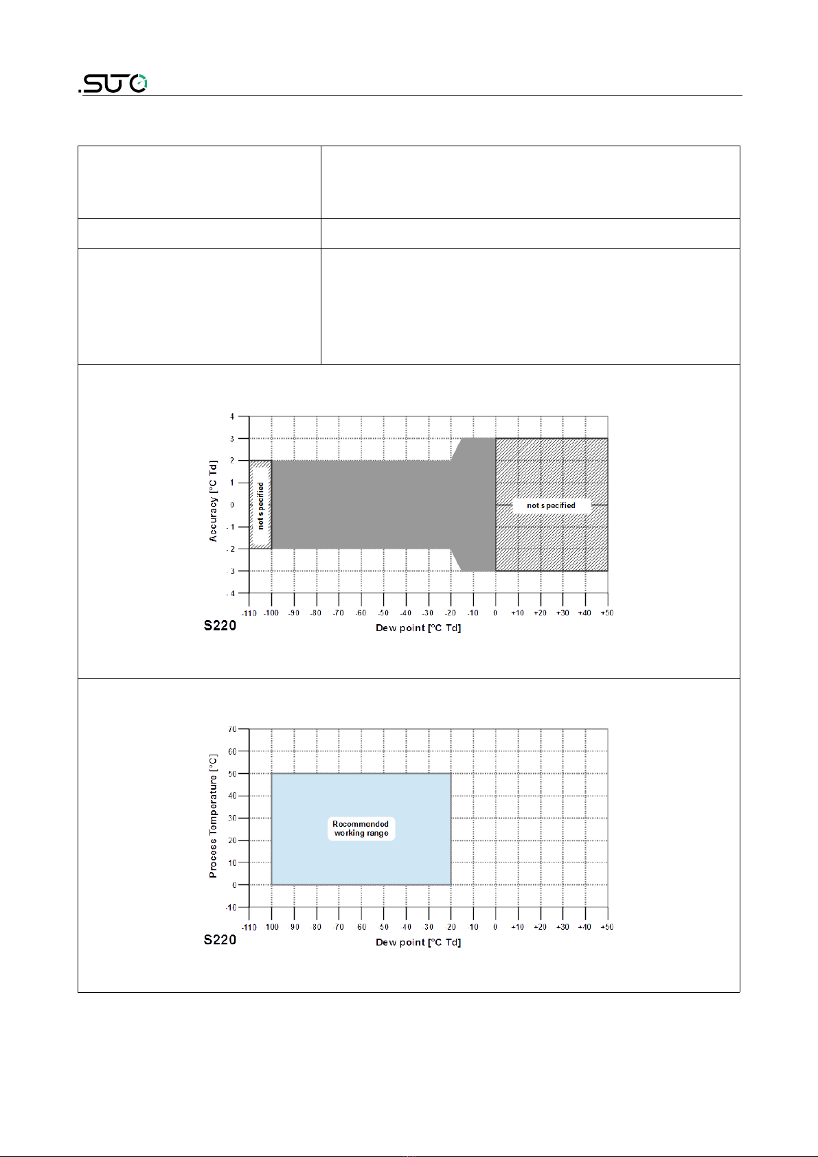
4.4 Accuracy ..............................................................................8
5. Dimensional drawing....................................................................9
6. Determination of the installation point..........................................10
7. Installation ..............................................................................10
7.1 Installation Requirements......................................................10
7.2 Installation Procedure ...........................................................11
7.3 Electrical connection ............................................................12
8. ignal outputs...........................................................................13
8.1 Analog output ......................................................................13
8.2 Modbus output ....................................................................14
9. Optional extra accessories..........................................................15
9.1 Measuring chambers ............................................................15
9.2 ervice kit...........................................................................15
10. Calibration..............................................................................16
11. Maintenance............................................................................16
12. Disposal or waste.....................................................................16
13. Warranty................................................................................17
Appendix A - Modbus communication example..................................18
Appendix B - LRC and CRC calculation..............................................20
S220 3

1. afety instructions
1. Safety instructions
Please check if this instruction manual accords to the
product type.
Please observe all notes and instructions indicated in this
manual. It contains essential information which have to be
observed before and during installation, operation and
maintenance. Therefore this instruction manual has to be read carefully
by the technician as well as by the responsible user / qualified
personnel.
This instruction manual has to be available at the operation site of the
dew point sensor at any time. In case of any obscurities or questions,
regarding this manual or the product, please contact the manufacturer.
ARNING!
Compressed air!
Any contact with quickly escaping air or bursting
parts of the compressed air system can lead to
serious injuries or even death!
•Do not exceed the maximum permitted pressure range (see
sensors label).
•Only use pressure tight installation material.
•Avoid that persons get hit by escaping air or bursting parts of the
instrument.
•The system must be pressureless during maintenance work.
ARNING!
Voltage used for supply!
Any contact with energized parts of the product, may
lead to a electrical shock which can lead to serious
injuries or even death!
•Consider all regulations for electrical installations.
•The system must be disconnected from any power supply during
maintenance work.
•Any electrical work on the system is only allowed by authorized
qualified personal.
4 S220

1. afety instructions
ARNING!
Permitted operating parameters!
Observe the permitted operating parameters, any
operation exceeding this parameters can lead to
malfunctions and may lead to damage on the
instrument or the system.
•Do not exceed the permitted operating parameters.
•Make sure the product is operated in its permitted limitations.
•Do not exceed or undercut the permitted storage and operation
temperature and pressure.
•The product should be maintained and calibrated frequently, at
least annually.
General safety instructions
•It is not allowed to use the product in explosive areas.
•Please observe the national regulations before/during installation
and operation.
Remarks
•It is not allowed to disassemble the product.
•Always use spanner to mount the product properly.
ATTENTION!
Measurement values can be affected by
malfunction!
The product must be installed properly and
frequently maintained, otherwise it may lead to
wrong measurement values, which can lead to
wrong results.
Storage and transportation
•Make sure that transportation temperature of the sensor is
between -30 ... +70°C.
•For storage and transportation it is recommended to use the
packaging which comes with the sensor.
•Please make sure that the storage temperature of the sensor is
between -20 ... 50°C.
S220 5

1. afety instructions
•Avoid direct UV and solar radiation during storage.
•For the storage the humidity has to be <90%, no condensation.
2. Application
The 220 is a dew point sensor which is designed to monitor the dew
point in industrial application within the permissible operating
parameters. These parameters can be found in the technical data
section.
The 220 can measure the following values:
•Temperature of the compressed air or gas.
•Humidity of the compressed air or gas.
•Dew point of the compressed air or gas.
The default factory settings are: temperature in °C, Humidity in % and
dew point in °C Td. Other units can be programmed by the optional
display or the service kit.
The 220 dew point sensor is not developed to be used in explosive
areas. For the use in explosive areas please contact the manufacturer.
The 220 dew point sensor is mainly used in compressed air systems in
industrial environment.
3. Features
•mall size makes it ideal for dryer installation.
•Measures dew point down to -100°C Td.
•Version with integrated pressure measurement.
•Various output versions available: 1 x 4 ... 20 mA, 2 x 4 ... 20 mA,
R -485 (Modbus), 4 ... 20 mA loop powered.
•IP65 casing provides robust protection in rough industrial
environment.
•Very fast response time ensures safe and reliable indication
whenever dew points are out of valid ranges.
•Can be installed directly into dryer through G ½” thread.
•High accuracy of ±2 °C dew point.
6 S220

4. Technical Data
4. Technical Data
4.1 General
Parameters tandard unit dew point: °C Td
tandard unit temperature: °C
other units: °F, K
tandard unit humidity: %
Principle of measurement Oscillating crystal
ensor QCM
Measuring medium Non-corrosive gases
Measuring range Dew point: -100 ... 0°C Td
Temperature: -30 ... 70°C
Pressure: -0.1 ... 1.6 MPa
Ambient temperature 0 ... 50°C
Operating pressure -0.1 ... 1.6 MPa
Casing material Process connection: stainless steel
Casing: zinc alloy
Protection class IP65
Dimensions ee dimensional drawing on the next page
crewing thread G ½” thread (I O 228/1);
Weight 204 g
4.2 Electrical Data
Power supply 12 ... 30 VDC / 30 mA
4.3 Output-Signals
Analog output 4 ... 20 mA, 3-wire
4 ... 20 mA, 2-wire
Analog output scaling 4 mA = -100°C Td
20 mA = +20°C Td
Modbus output R -485
S220 7

4. Technical Data
4.4 Accuracy
Accuracy Dew point: ±2°C
Temperature: 0.3°C
Pressure: 0.05 bar
Repeatability ± 0.5°C
tated accuracy at Ambient/process temperature 23°C ± 3°C
Process temperature 23°C ± 3°C
Ambient/process humidity <95% rH, no
condensation
Airflow > 2 l/min at the sensor tip
Accuracy:
Valid working range:
8 S220

6. Determination of the installation point
In order to maintain the accuracy stated in the technical data, the
sensor must be installed correctly. The air must flow on to the sensor
tip, otherwise it will lead to wrong measurement values. For further
instructions, please read the next chapter carefully.
Please consider that enough space exists at your site for a adequate
installation as described in this manual.
ATTENTION!
rong measurement is possible, if the sensor is not
installed correctly.
•The sensor is for indoor use only! At an outdoor installation, the
sensor must be protected from solar radiation and rain.
•It is strongly recommend not to install 220 permanently in wet
environment as it exists usually right after a compressor outlet.
7. Installation
Before installing the sensor, please make sure that all components listed
below are included in your package.
Qty Description Item No.
1 ensor 699 0220
699 0221
699 0222
699 0223
699 0224
699 0225
1 M12 plug C219 0059
1 Instruction manual No P/N
1 Calibration certificate No P/N
7.1 Installation Requirements
The flowing air or gas has to pass the sensor tip for a proper
measurement. This can be realized with a measurement chamber. For a
installation without measuring chamber you need to concern the
installation depth which is described in the next chapter.
10 S220

7. Installation
7.2 Installation Procedure
The following steps explain the procedure of an appropriate installation.
Installation of the sensor with measurement chamber
1. connect the sensor with
the measurement
chamber.
2. Connect the sensor and
the measurement
chamber with the fast
connector.
Installation of the sensor without measurement chamber
•Install the sensor only if
the system is
pressureless.
•Not less than 1/3 of the
sensor tip should be
inside of the pipe. For
this please check the
size of the nozzle.
•The inner thread has to
be G 1/2”.
S220 11

7. Installation
Remarks
Please install the sensor only
in the recommended area
like you can see in the
picture. A upside down
installation is not permitted.
Please consider that the
distance to the vertical level
must be >30°.
Removal of the sensor
To remove the sensor unscrew the sensor from the measurement
chamber or from the nozzle. Please observe that the system is
pressureless when the sensor is removed.
7.3 Electrical connection
Connection pins connector plug M12
Connection pins
(view from the clamping side)
Pin assignment connector plug M12
Model Pin 1 Pin 2 Pin 3 Pin 4 Pin 5
0220 DI -VB+VB+l1NA
0221 DI -VB+VB+I1+I2
0222 DI -VB+VB+D -D
12 S220

7. Installation
0223 DI -VB+VB+I1+I2
0224 DI -VB+VB+D -D
0225 DI -VB+VB
Wire colour brown white blue black grey
Legend to pin assignment
DI Digital signal (internal use)
-VBNegative supply voltage
+VBPositive supply voltage
+I1Active 4 ... 20 mA signal
+I2Active 4 ... 20 mA signal
+D Positive data Modbus
-D Negative data Modbus
NA Not applicable
8. Signal outputs
8.1 Analog output
The sensor has an analog output range of 4 ... 20 mA. Depending on
the model it is a 3-wire active analog output or a 2-wire passive analog,
please have a look to the table below. This output is scaled to:
•4 mA = -100°C Td
•20 mA = +20°C Td
For other ranges, please contact the manufacturer. The analog output
can be allocated to the temperature, the dew point and the humidity.
Model Analog output
699 0220 1 x 4 ... 20 mA, 3-wire (active)
699 0221
699 0223
2 x 4 ... 20 mA, 3-wire (active)
699 0225 1 x 4 ... 20 mA, 2-wire (passive)
S220 13

8. ignal outputs
8.2 Modbus output
Model Digital output
699 0222, 699 0224 R -485, Modbus RTU
Mode : RTU
Baud rate : 19200
Device address : 1
Framing / parity / stop bit : 8, non, 1
Response time : 1 second
Response delay : 0 ms
Inter-frame spacing : 7 char
Remarks
•Modbus communication settings can be changed by the service
software.
•To learn more about Modbus communication, see Appendix A -
Modbus communication example and Appendix B - LRC and CRC
calculation.
14 S220

8. ignal outputs
Index Channel description Unit Format Length Modbus
address
0 Temperature °C or °F FLOAT 4-Byte 0
3 Relative humidity % FLOAT 4-Byte 2
5 Pressure bar FLOAT 4-Byte 4
7 Pressure dew point °C or
° F
FLOAT 4-Byte 6
9 Atmosphere dew
point
°C or
° F
FLOAT 4-Byte 8
11 Mixing ratio g/kg FLOAT 4-Byte 10
13 Absolute humidity g/m3 or
mg/m3
FLOAT 4-Byte 12
15 Atmosphere absolute
humidity
g/m3 or
mg/m3
FLOAT 4-Byte 14
17 Volume ration ppmv FLOAT 4-Byte 16
19 Reserved Reserve 4-Byte 18
9. Optional extra accessories
9.1 Measuring chambers
There are different types of measuring chambers, for example
measuring chamber with fast connector, by-pass-by chamber with in
and out connection, measuring chamber for dryer installation or high
pressure chamber. For more information please contact your retailer or
the manufacturer.
9.2 Service kit
The service kit is used to connect the sensor with the PC. ensor
parameters such as analog output scaling, alarm values, units etc. can
be easily changed by using the service kit.
The diagram below shows the connection when using the optional
service kit. Please ensure that also in this case the power supply of
either 220 or of the service kit is connected because the U B port
cannot supply enough power.
S220 15

9. Optional extra accessories
10. Calibration
The sensor is calibrated ex work. The exact calibration date is printed
on the certificate which is supplied together with the sensor. The
accuracy of the sensor is regulated by the on site conditions,
parameters like oil, high humidity or other impurities can affect the
calibration and furthermore the accuracy. However we recommend to
calibrate the instrument at least once per year. The calibration is
excluded from the instruments warranty. For this please contact the
manufacturer.
11. Maintenance
Please observe from time to time the sinter cap. If it appears to be
dirty, it is recommended to replace it for this please contact the
manufacturer.
ATTENTION!
A dirty/wet/contaminated sinter cap or sensor tip
may lead to a longer response time and to wrong
measurements.
12. Disposal or waste
Electronic devices are recyclable material and do not
belong in the household waste.
The sensor, the accessories and its packings must be
disposed according to your local statutory requirements.
The dispose can also be carried by the manufacturer of the
product, for this please contact the manufacturer.
16 S220

13. Warranty
13. arranty
UTO provides a warranty for this product of 24 months covering the
material and workmanship under the stated operating conditions from
the date of delivery. Please report any findings immediately and within
the warranty time. If faults occurring during the warranty time UTO
will repair or replace the defective unit, without charge for labour and
material costs but there is a charge for other service such as transport
and packing costs.
Excluded from this warranty is:
•Damage caused by:
◦Improper use and non-adherence to the instruction manual.
◦Use of unsuitable accessories.
◦External influences (e.g. damage caused by vibration, damage
during transportation, excess heat or moisture).
The warranty is cancelled:
•If the user opens the measurement instrument without a direct
request written in this instruction manual.
•If repairs or modifications are undertaken by third parties or
unauthorised persons.
•If the serial number has been changed, damaged or removed.
Other claims, especially those for damage occurring outside the
instrument are not included unless responsibility is legally binding.
Warranty repairs do not extend the period of warranty.
ATTENTION!
Batteries have a reduced warranty time of 12
month.
S220 17

Appendix A - Modbus communication example
03 (0x03) Read holding register
Request Response
lave address 1 byte lave address 1 byte
Function code 1 byte Function code 1 byte
tarting address
Hi
1 byte Byte count 1 byte
tarting address
Lo
1 byte Register Hi 1 byte
No. of points Hi 1 byte Register Lo 1 byte
No. of points Lo 1 byte : :
CRC 2 bytes Register Hi 1 byte
Register Lo 1 byte
CRC 2 bytes
05 (0x05) rite single coil
Request Response
lave address 1 byte lave address 1 byte
Function code 1 byte Function code 1 byte
Coil address Hi 1 byte Coil address Hi 1 byte
Coil address Lo 1 byte Coil address Lo 1 byte
Data Hi 1 byte Data Hi 1 byte
Data Lo 1 byte Data L 1 byte
CRC 2 bytes CRC 2 bytes
18 S220

Appendix A - Modbus communication example
16 (0x10) rite multiple registers
Request Response
lave address 1 byte lave address 1 byte
Function code 1 byte Function code 1 byte
tarting address
Hi
1 byte tarting address
Hi
1 byte
tarting address
Lo
1 byte tarting address
Lo
1 byte
No. of registers
Hi
1 byte No. of registers
Hi
1 byte
No. of registers
Lo
1 byte No. of registers
Lo
1 byte
Byte count 1 byte CRC 2 bytes
Data Hi 1 byte
Data Lo 1 byte
: :
Data Hi 1 byte
Data Lo 1 byte
CRC 2 bytes
17 (0x11) Report slave ID
Request Response
lave address 1 byte lave address 1 byte
Function code 1 byte Function code 1 byte
CRC 2 bytes Byte count 1 byte
lave ID 2 bytes
Device run
indicator
2 bytes
Product code 2 bytes
Product name 20 bytes
CRC 2 bytes
S220 19

Appendix B - LRC and CRC calculation
LRC generation
The Longitudinal Redundancy Checking (LRC) field is one byte,
containing an 8–bit binary value. The LRC value is calculated by the
transmitting device, which appends the LRC to the message. The device
that receives recalculates an LRC during receipt of the message, and
compares the calculated value to the actual value it received in the LRC
field. If the two values are not equal, an error results.
The LRC is calculated by adding together successive 8–bit bytes in the
message, discarding any carries, and then two’s complementing the
result. The LRC is an 8–bit field, therefore each new addition of a
character that would result in a value higher than 255 decimal simply
‘rolls over’ the field’s value through zero. Because there is no ninth bit,
the carry is discarded automatically.
A procedure for generating an LRC is:
1. Add all bytes in the message, excluding the starting ‘colon’ and
ending CRLF. Add them into an 8–bit field, so that carries will be
discarded.
2. ubtract the final field value from FF hex (all 1’s) to produce the
ones–complement.
3. Add 1 to produce the twos–complement.
Placing the LRC into the Message
When the 8–bit LRC (2 A CII characters) is transmitted in the message,
the high–order character will be transmitted first, followed by the low–
order character. For example, if the LRC value is 61 hex (0110 0001):
Colon Addr Func Data
Count Data Data Data Data LRC
Hi
LRC
Lo CR LF
“6”
0x36
“1”
0x31
Example: an example of a C language function performing LRC
generation is shown below.
The function takes two arguments:
unsigned char *auchMsg; /* A pointer to the message buffer containing binary data */
/* to be used for generating the LRC, */
unsigned short usDataLen; /* The quantity of bytes in the message buffer. */
LRC generation function
20 S220
Table of contents
Other SUTO Accessories manuals
Popular Accessories manuals by other brands

Physik Instrumente
Physik Instrumente E-509 Series user manual

Family Self Care
Family Self Care SelfCare 1 manual

Honeywell Home
Honeywell Home DC312 P2USB Series manual

PCB Piezotronics
PCB Piezotronics IMI SENSORS M641B61 Installation and operating manual

Intenso
Intenso P10000 user manual

KRACK
KRACK SM Series OPERATING AND INSTALLATION Manual