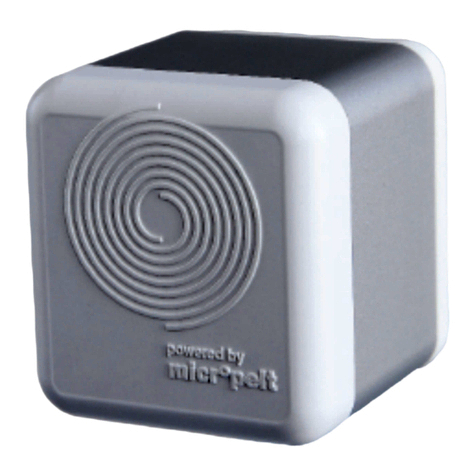
Micropelt MVA008 Application guide

1 MVA008 Revision History ...................................................................................................................................................................3
2 MVA008 Intended use.........................................................................................................................................................................4
3 MVA008 Safety....................................................................................................................................................................................5
4 MVA008 General description..............................................................................................................................................................6
5 MVA008 Operating Instructions.........................................................................................................................................................7
5.1 Installation with Manual Pairing .......................................................................................................................................................7
6 MVA008 Notes on radio operation.....................................................................................................................................................9
6.1 Transmission range............................................................................................................................................................................9
6.2 Other interference sources................................................................................................................................................................9
6.3 Loss of communication with the room controller............................................................................................................................9
7 MVA008 Communication profile EEP A5-20-01...............................................................................................................................10
7.1 Protocol data overview....................................................................................................................................................................10
7.2 Setpoint Selection (DB1.2, RCU to MVA004) ...................................................................................................................................11
7.3 Valve position [%] and Set temperature [°C] in actuator mode (DB3, RCU to MVA004)...............................................................11
7.4 Summer Mode (DB1.3).....................................................................................................................................................................11
7.5 Recognition of valve position and reference run ...........................................................................................................................11
7.6 Example of a radio protocol ............................................................................................................................................................11
8 MVA008 Remote Commissioning (EN).............................................................................................................................................16
8.1 EnOcean Link Table .........................................................................................................................................................................16
8.2 Outbound Teach-in..........................................................................................................................................................................16
8.3 ReMan supported functions ............................................................................................................................................................16
8.4 ReCom supported standard functions............................................................................................................................................17
8.5 ReCom supported MVA internal parameter....................................................................................................................................18
9 MVA008 Energy Harvesting ..............................................................................................................................................................21
9.1 Energy storage bit ES .......................................................................................................................................................................21
9.2 Forced heating .................................................................................................................................................................................21
10 MVA008 Battery recharging .............................................................................................................................................................22
10.1 Flow chart instructions MVA008 and MVA009:................................................................................................................................23
10.2 Video instruction charge startup (MVA008 without cover prints, is identical to MVA009): ..........................................................24
10.3 Charging curve LiFePO4 cell in the MVA EnOcean series: ..............................................................................................................24
11 MVA008 Product-ID and Label .........................................................................................................................................................25
12 MVA008 Technical Data....................................................................................................................................................................26
13 MVA008 Valve connection................................................................................................................................................................28

Copyright Micropelt
MVA008 Revision History – 3
1 MVA008 Revision History
Rev.-Nr. Description of the revision Revised by Date
v1e v1e was taken from
Micropelt_MVA004_1DSMVA004_0720v13e.docx
Volkert 27.03.2023
Datei
Geändert
Micropelt_MVA004_1DSMVA004_0720v13e.docx
2023-03-28 by Fritz Volkert

Copyright Micropelt
MVA008 Intended use – 4
2 MVA008 Intended use
The Micropelt MVA product series has been designed for use with controlling water-filled heating radiators. Any other use –
including control of floor heating systems – is not permitted and can result in malfunctions or damage. It is important to comply
with the safety notice included in these operating instructions.

Copyright Micropelt
MVA008 Safety – 5
•
•
•
•
•
•
•
•
•
•
3 MVA008 Safety
This appliance is not intended for use by persons (including children) with reduced physical, sensory or mental capabilities, or a
lack of experience and knowledge, unless they have been given supervision or instruction concerning the use of the device by a
person responsible for their safety.
This product is not a toy. Children shall be advised to refrain from playing with it.
The metallic part of the unit’s housing serves as a heat sink. Be sure that the air circulation around it is not obstructed by
furniture, curtains, plants, or any other object.
If the device has been stored in a cold environment, make sure that it resumes close to room temperature before use.
This is to prevent damage due to condensation.
The thermostatic head is designed for indoor use only. Do not allow the thermostatic head to get wet. Its sensitive
electronics can be affected.
The unit is best cleaned with a dry or slightly damp cloth. Do not use aggressive cleaning agents or solvents.
Refrain from exposing the unit to environmental stress such as high mechanical forces (do not step on it), strong
vibrations, direct sunlight or extreme temperatures.
The unit must not be disassembled or modified. There are no user-serviceable parts inside.
Be aware that correct operation can be affected by strong electromagnetic fields. Typical sources of such are mobile
phones, 2-way radios, RC transmitters, microwave ovens, electric motors.
The thermostatic head has been designed and must solely be used for the purpose of controlling a M30 x 1.5 circulation
valve. Any other use may pose a hazard to the device itself, to the equipment involved, or to the health of the user.
When operating the device in a workplace environment, be sure to observe the workplace regulations that may apply.
In case of questions, please contact:

Copyright Micropelt
MVA008 General description – 6
4 MVA008 General description
This document defines the properties of Micropelt’s battery free thermostatic radiator valve MVA008. The unit is directly
mounted onto radiator valve bodies (M30x1,5 thread or Valve adapter ), where it controls the room temperature, based on
signals of a central controller. It is radio-controlled and powered by energy harvesting, so it neither requires any cabling work
nor does it consume batteries. It is designed for maintenance-free operation. The wireless design makes the unit ideal for retrofit
installation and cost-sensitive projects, where cabling cost is prohibitive. A room controller can be used to conveniently set time
programs that set the room temperature to different values at different times of the day. By lowering the room temperature in
times of absence, heating costs can be saved without any loss of comfort. Reducing the room temperature by just a few ° C also
leads to cost savings.
The actuator generates the energy required for operation (engine running, sensors and radio communication) by means of a
built-in thermoelectric generator (TEG) and is therefore maintenance-free. This is supplied from the temperature difference
between the radiator heat and the ambient temperature (usually the room temperature). An additional source of energy, such as
a battery or a mains connection is not required. The internal energy storage is pre-charged upon delivery. This means that
sufficient energy is available for the installation and approximately one year of normal operation. The internal storage unit is
recharged through excess energy generated during heating operation, which means that sufficient energy is available for year-
round operation.
At its user interface, MVA008 has a red and a green LED. Two internal temperature sensors are used with its internal temperature
controller and freeze protection (ambient sensor) and the automatic radio duty cycle control of 2, 5 or 10 minutes (flow
temperature sensor).
MVA008 is operating with EnOcean standard EEP A5-20-01 (4BS) in either valve position or set temperature mode. According to
the standard protocol, the unit reports to the room controller every 2/5 or 10 minutes (auto radio interval) transmitting its
current valve position and status information. The room controller responds with either a new control value in the value range
0% (valve closed) to 100% (valve maximum open) or setpoint temperature (0 ... 40 ° C). When the setpoint changes, the actuator
motor moves the motor to the new position. When operating with the setpoint temperature, we recommend to use a separate,
external room temperature sensor that transmits its temperature to the room controller, which forwards it to the MVA004 as part
of the A5-20-01 protocol. By heat input from the radiator in the unit, there are deviations between the measured and actual room
temperature, which are compensated by means of an integrated correction function. The first 30 minutes after activation are
used to calibrate the offset compensated ambient temperature value. During that time, the valve will transmit its internal and
fixed temperature value of 20°C and then automatically switch over to the corrected value.
The actuator is delivered in mounting position (motor position is fully retracted). The actuator has an internal valve recognition
(ACO). In addition to a blockage, the ACO bit also signals any unsuccessfully completed reference run and when starting from
mounting position. A dynamic zero-point correction ensures that the valve closes in the long term. Unmounted but activated will
automatically move the motor back to mounting position to switch-off the device.
In the event of a radio failure (6 unsuccessful communication attempts), the internal temperature controller is activated, and the
radiator is regulated to a preset 21 ° C. A change of the radio interval does not take place. The drive goes into normal operation
as soon as the radio communication is restored.
When operating in unheated rooms, the internal storage will be discharged. The unit then moves to 50% open position trying to
recharge its storage. Operation in little or unheated rooms must be avoided since normal operation can not be guaranteed and a
manual battery recharging is needed.
MVA008 is designed for low power operation. Therefore, all ReMan and ReCom operations are internally time limited and must
be executed within less than 8 seconds. It is strongly recommended to execute ReMan only for initial teach over the air (Link
Table) and device configuration (RESET) following its initial deployment.
MVA008 has a button lock after one-hour function integrated that will prevent from unintended use.

Copyright Micropelt
MVA008 Operating Instructions – 7
5 MVA008 Operating Instructions
You find the quick-start guide here: MVA008 Quickstart Guide
5.1 Installation with Manual Pairing
No Objective Button
No.
Action LED Activity Reasons for
failure
1 Pairing from
mounting position
(= shipping
condition = OFF)
or normal
operation (while
buttons not
locked)
Turn dial to end
position
Left OR Right and
hold 5 seconds
until 1x green or
3x red LED
Unit does pair and
remains in mounting
position = shipping
condition = OFF
If unit is not in mounting
position, it moves to
mounting position now.
Success: Single
green flash
Failure: Triple red
flash
Controller or
gateway either
not present or
not in pairing
mode, so that
pairing fails
2 Mounting
Mount the actuator
before executing run-in
sequence and normal
operation
3 Run-in sequence
and normal
operation from
mounting position
Turn to end
position
Left OR Right for
short press (< 1
second)
Unit executes run-in
sequence; radio
communication occurs
every 10 seconds for 10
minutes, and then reverts
to every 10 minutes.
One hour after this
action, the pushbutton
switches will lock and can
only be unlocked, by
performing RESET (5.)
Success: Single
green flash
Failure: Triple red
flash
Motor or gear
error
4 Get new target
value (while
buttons not
locked)
Turn to end
position
Left OR Right for
short press (< 1
second)
Unit immediately gets
target value from
controller / gateway, then
moves to the new target
Success: Single
green flash
Failure: Triple red
flash
Unit cannot
contact the
controller or
gateway
5 Return to
mounting position
Turn dial to end
position
Left OR Right and
hold 5 seconds
until single green
flash
Green LED appears,
followed a triple red LED.
The device will turn the
motor back to mounting
position and switch off.
Success: Single
green flash followed
by triple red flash

Copyright Micropelt
MVA008 Operating Instructions – 8
6 Deactivate button
lock
and
RESET followed by
normal operation
Pull the dial
straight off and
press both
buttons
simultaneously
for 10 seconds.
The unit enters normal
operation, assuming it is
paired. For 60 min, the
unit will accept a 5-
second long-press of any
button and for 10
minutes, it will run at a
10-second radio
communication interval.
It contacts the
controller / gateway
immediately after RESET.
After 10 seconds 1x
green (RESET
activated),
then 2x red (new
start),
after a short break 1x
green (normal
operation with
successful
communication) or
3x red
(communication
error, mounting
error)
Unit cannot
contact the
controller or
gateway it has
been paired
with
or unit has
never been
paired.
Mounting or
motor problems

Copyright Micropelt
MVA008 Notes on radio operation – 9
6 MVA008 Notes on radio operation
6.1 Transmission range
The radio transmission range is limited by both the distance between transmitter and receiver, and by interference. Indoors,
building materials play an important role. Major reflections and signal losses are due to metallic parts, such as reinforcements in
walls and metallized foils, which are used on thermal insulation products.
Penetration of radio signals:
Material →Penetration
Wood, gypsum, uncoated glass →90..100 %
Brick, chipboard →65.. 95 %
Reinforced concrete →10.. 90 %
Metal, aluminum facings →0.. 10 %
For an evaluation of the environment, please see guide values listed below:
Conditions →Range / penetration
Line-of-sight →Typ 30 m range in passages, up to 100 m in halls
Plasterboard and wood walls →Typ 30 m range through max. 5 walls
Brick and foamed concrete walls →Typ 20 m range through max. 3 walls
Reinforced concrete walls & ceilings →Typ 10 m range through max. 1 ceiling
Supply blocks and lift shafts should be treated as shields.
In addition, the angle at which the signal enters the wall has to be considered. A shallow angle increases the effective wall
strength as well as the attenuation of the signal. Whenever possible, signals should enter walls perpendicularly. Alcoves should
be circumvented.
For additional information, refer to the EnOcean White Paper “EnOcean Wireless Systems – Range Planning Guide”.
6.2 Other interference sources
Common sources of interference are devices that generate high-frequency signals. These are typically computers, audio-/video
systems, electronic transformers and ballasts. The distance of the actuator to such devices should be more than 0.5 m.
6.3 Loss of communication with the room controller
If the actuator cannot establish a dependable radio communication with the room controller, i.e. more than 6 times in sequence
the room controller does not receive a radio signal, then the actuator switches to a reduced radio pattern. The typical 10 minute
radio period is extended to one transmission every hour, reducing the energy consumption while radio contact is interrupted. In
addition, the actuator enters the safe position. Once the radio contact to the room controller recovers, the actuator reverts to
requesting instructions from the controller every 10 minutes.

Copyright Micropelt
MVA008 Communication profile EEP A5-20-01 – 10
•
•
•
•
•
7 MVA008 Communication profile EEP A5-20-01
The wireless communication is cyclical and bidirectional using only the EnOcean Equipment Profile EEP A5 20-01 (Battery-
Powered Actuator).
Download Encoder/Decoder
Datei
Geändert
EnOcean A5-20-01 Analyzed.xlsx
2023-03-28 by Fritz Volkert
7.1 Protocol data overview
7.2 Setpoint Selection (DB1.2, RCU to MVA004)
7.4 Summer Mode (DB1.3)
7.5 Recognition of valve position and reference run
7.6 Example of a radio protocol
7.1 Protocol data overview
Transmit mode from MVA to controller/ gateway/
server
Receive mode from controller / gateway / server to MVA
DB3.7…DB3.0 (CV) Current valve position
0...100%, linear n=0...100
DB3.7…DB3.0 (SP) New valve position (0...100% ~
0x00…0x64) or Target temperature
(0…40°C ~ 0x00…0xFF)
Selection with SPS DB1.2
DB2.7 Not used DB2.7…DB2.0
(TMP)
Room temperature from room
sensor (0…40ºC ~ 0xFF…0x00*) for
operation with the internal MVA
ambient sensor must be set to 0x00
DB2.6 (ENIE) Active energy harvesting (valve
is hot)
DB1.7....DB1.4 Not used (set to “zero”)
DB2.5 (ES) Energy storage sufficiently
charged
DB1.3 (SB) Summer mode transmit / receive
time interval 8 hours
DB2.4 (BCAP) Storage capacity sufficient
(analog DB_2. Bit_5)
DB1.2 (SPS)*1 Setpoint Selection
0: Valve pos. (0…100%)
1: Temp. setpoint (0…40°C)
DB2.3 Not used DB1.1…DB1.0 Not used (set to “zero”)
DB2.2 (FTS) Temperature sensor failure DB0.7…DB0.4 Not used (set to “zero”)
DB2.1 (DWO) Window open detection DB0.3 (LRNB) LRN Bit, defined for data telegram
DB2.0 (ACO) Motor failure DB0.2…DB0.0 Not used (set to “zero”)

Copyright Micropelt
MVA008 Communication profile EEP A5-20-01 – 11
•
DB1.7…DB1.0
(TMP)
Ambient temperature MVA
(0…40°C ~ 0x00…0xFF)
DB0.7…DB0.4 Not used
DB0.3 (LRNB) LRN Bit, defined for data
telegram
DB0.2…DB0.0 Not used
*1 IMPORTANT NOTICE:
When operated in Temperature setpoint mode (SPS=1), every valid temperature setpoint (°C) value received is internally stored
and used in case of radio loss situations. This allows the user to control the radio loss safety temperature value even when the
device is used in valve position mode SPS=0.
More information is available in the latest release version of the published equipment profiles EEP of the EnOcean Alliance.
http://www.enocean-alliance.org
7.2 Setpoint Selection (DB1.2, RCU to MVA004)
Selection whether A5-20-01 and the actuator is used with Valve Position (Controller running in the room or building control
system) or with its internal temperature control loop.
7.3 Valve position [%] and Set temperature [°C] in actuator mode (DB3, RCU to MVA004)
The external radio partner transmits the temperature setpoint for the internal controller (0 ... + 40°C, DB3.7 ... DB3.0 = 0 ... 255).
The use of a separate, external room temperature sensor is recommended whose room temperature (DB2.7 ... DB2.0) is
transmitted to the drive by the room controller as part of the A5-20-01 protocol. The internal controller thus does not use the
ambient temperature measured in the near field of the radiator, but the actual room temperature.
When operating with an internal temperature sensor, DB2.7 ... DB2.0 must be set to 0x00. Values not equal to 0x00 are
interpreted as sent room temperatures and thus lead to faulty control behavior.
Valve position (%):The external radio partner transmits a 0 ... 100% control signal (DB3.7 ... DB3.0 = 0 ... 100) and converts it into
an actuating movement by the actuator (0% = closed valve / 100% = completely open valve).
7.4 Summer Mode (DB1.3)
When the actuator receives the status message „Summer mode ON“ from the external radio master, then the transmit/receive
interval is increased from 2/5/10 minutes to 8 hours. It is possible to wake up the iTRV through 1 x pressing the push button.
Then the iTRV receives the new setting from the room controller.
7.5 Recognition of valve position and reference run
The valve actuator recognizes during the teach-in the closing position of the valve. During operation the valve actuator does a
full stroke (self-calibration) after every 2nd week, to avoid malfunction of the valve. It is not intended to trigger the recognition of
the valve position via room controller.
7.6 Example of a radio protocol
Radio protocol of valve actuator MVA to server /controller /gateway
Example in HEX "0x32 0x70 0x89 0x08"
DB3.7…DB3.0 = 0x32 = 50: valve position is 50%

Copyright Micropelt
MVA008 Communication profile EEP A5-20-01 – 12
•
•
•
•
•
•
•
•
•
•
•
DB2.7…DB2.0 = 0x70 includes
o DB2.4 = 1 Energy storage capacity sufficient
o DB2.5 = 1 Energy storage charged
o DB2.6 = 1 Harvesting active
DB1.7…DB1.0 = 0x89 = 137: Internal temperature = 40*DB.1/255 = 40*137/255 = 21,5 °C
DB0.7…DB0.0 = 0x08: Data telegram
Radio protocol from server /controller /gateway to valve actuator
VALVE POS: Example in HEX "0x05 0x77 0x00 0x08"
DB3.7…DB3.0 = 0x05 = 5: new valve position is 5%
DB2.7…DB2.0 = 0x77 = 119: room temperature = 255 - 119 = 136 => 40 * 136 / 255 = 21,3 °C
DB1.7…DB1.0 = 0x00:
o DB1.3 = 0: regular default radio cycle (no summer mode)
o DB1.2 = 0: DB3.7…DB3.0 is set to valve position %
DB0.7…DB0.0 = 0x08: Data telegram
SET_TEMP: Example in HEX "0x80 0x81 0x04 0x08"
DB3.7…DB3.0 = 0x80 = 128: New target temperature is 40 * 128 / 255 = 20,1°C
DB2.7…DB2.0 = 0x81 = 129: room temperature = 255 - 129 = 126 => 40 * 126 / 255 = 19,8 °C
DB1.7…DB1.0 = 0x04:
o DB1.3 = 0: regular default radio cycle (no summer mode)
o DB1.2 = 1: DB3.7…DB3.0 is set to internal temp.-controller with default duty cycle (Summer bit not active)
DB0.7…DB0.0 = 0x08: Data telegram
DIRECTION-1 MVA004 to Control unit /Gateway
Actuator →Controller / Gateway
4 Byte: 32708908
HEX BIN DEC
DB3.7-0 32 00110010 50 CV = Current valve opening = 50 %
DB2.7-0 70 01110000 112
SO DB2.7 0 0 = Normal operation 1 = Service on
ENIE DB2.6 1 0 = no energy input 1 = Energy input enabled
(Harvesting active)
ES DB2.5 1 0 = Energy storage low 1 = Energy storage sufficiently
charged

Copyright Micropelt
MVA008 Communication profile EEP A5-20-01 – 13
BCAP DB2.4 1 0 = Battery low,
replace soon
1 = Battery OK
DB2.3 0
FTS DB2.2 0 0 = Temp sensor OK 1 = Temp sensor out of range
DB2.1 0
ACO DB2.0 0 0 = Actuator normal
operation
1 = Actuator obstructed
DB1.7-0 89 10001001 137 TMP = Ambient temperature from actuator = 21.5 ºC
DB0.7-0 08 00001000 8
LRN Type DB0.7 0 0 = not used [no EEP & Mfg
ID)
1 = not used [with EEP & Mfg ID)
EEP Result DB0.6 0 0 = not used [EEP not
supported]
1 = not used [EEP supported]
LRN Result DB0.5 0 0 = not used [Sender ID
deleted]
1 = not used [Sender ID stored]
LRN Status DB0.4 0 0 = not used [Teach-In
query]
1 = not used [Teach-In response]
LRNB DB0.3 1 0 = Teach-in Telegram 1 = Data Telegram
DB0.2 0 0 = not used 1 = not used
DB0.1 0 0 = not used 1 = not used
DB0.0 0 0 = not used 1 = not used
DIRECTION-2 Control unit / Gateway to MVA004
Controller / Gateway → Actuator
4 Byte: 80810408

Copyright Micropelt
MVA008 Communication profile EEP A5-20-01 – 14
HEX BIN DEC
DB3.7-0 80 10000000 128 SP = Valve position = 128 %
SP = Valve temperature setpoint = 20.1 ºC
DB2.7-0 81 10000001 129 TMP = Temperature from controller / gateway = 19.8 ºC
DB1.7-0 04 00000100 4
DB1.7 0
DB1.6 0
DB1.5 0
DB1.4 0
SB DB1.3 0 0 = Normal Operation 1 = Summer bit, extended
sleep time
SPS DB1.2 1 0 = DB3 is valve position [%] 1 = DB3 is temperature set
point [ºC]
DB1.1 0
DB1.0 0
DB0.7-0 08 00001000 8
LRN Type DB0.7 0 0 = not used [no EEP & Mfg
ID)
1 = not used [with EEP & Mfg
ID)
EEP Result DB0.6 0 0 = not used [EEP not
supported]
1 = not used [EEP supported]
LRN Result DB0.5 0 0 = not used [Sender ID
deleted]
1 = not used [Sender ID
stored]
LRN Status DB0.4 0 0 = not used [Teach-In
query]
1 = not used [Teach-In
response]
LRNB DB0.3 1 0 = Teach-in telegram 1 = Data telegram
DB0.2 0 0 = not used 1 = not used

Copyright Micropelt
MVA008 Communication profile EEP A5-20-01 – 15
DB0.1 0 0 = not used 1 = not used
DB0.0 0 0 = not used 1 = not used

Copyright Micropelt
MVA008 Remote Commissioning (EN) – 16
•
•
•
•
•
•
•
•
•
•
•
•
8 MVA008 Remote Commissioning (EN)
8.1 EnOcean Link Table
8.2 Outbound Teach-in
8.3 ReMan supported functions
8.4 ReCom supported standard functions
8.5 ReCom supported MVA internal parameter
8.1 EnOcean Link Table
MVA008 supports the following number of tech-in relationships:
Inbound EnOcean Link Table: 0 Teach-in relationships (not existing)
Outbound EnOcean Link Table: 3 Tech-in relationships
Comments:
MVA008 uses an outbound link table only, inbound relationships are not supported. Manually erasing the outbound link table is
not possible. Manual pairing (teach-in) however overwrites the first entry of the outbound link table, clearing the other two
entries.
8.2 Outbound Teach-in
Outbound teach-in is supported for EEP A5-20-01 (4BS)
Two options are available to teach-in MVA004 with an external Gateway/Controller:
Manually via teach-in message (4BS version 3)
Using Remote commissioning
8.3 ReMan supported functions
PING
LOCK, UNLOCK (Default Security ID: 0xFFFFFFFE)
SET CODE
QUERY ID, QUERY STATUS
For further details, pls. refer to the document “Remote Management” by EnOcean GmbH: https://www.enocean.com/fileadmin/
redaktion/pdf/tec_docs/RemoteManagement.pdf

Copyright Micropelt
MVA008 Remote Commissioning (EN) – 17
•
•
•
•
•
•
•
•
8.4 ReCom supported standard functions
Remote Commissioning Mandatory Commands Bundle:
Remote Commissioning Acknowledge
Get Product ID Query & Response
EnOcean Link Table Basic Commands Bundle
Get Link Table Metadata Query & Response
Get Link Table Query & Response
Set Link Table Content
Configuration Parameters Bundle
Get Device Configuration Query & Response
Set Common Configuration Query
RESET DEVICE DEFAULTS
RESET DEVICE DEFAULTS: MVA will execute reference run and reset all internal parameter to DEFAULT values (Table 4.5). Link
connections and Security Code will not be changed.

Copyright Micropelt
MVA008 Remote Commissioning (EN) – 18
8.5 ReCom supported MVA internal parameter
Related xml (DDF) file can be found here: Overview MVA EnOcean
Description INDEX 0 = environment to setpoint offset [K]
The ambient-to-setpoint offset [K] is a function related to the ambient sensor to correct the temperature measured in the device.
For structural reasons and due to the near field of the radiator, the temperature measured on the MVA unit is subject to
deviations from the actual room temperature. In automatic mode (0x00), the drive uses its integrated flow (valve adapter) sensor
to determine the actual room temperature using an approximation function. With the other settings, an absolute value is
subtracted from or added to the measured temperature. Example setting 0x07… + 3K: The temperature output by the ambient
sensor is the effectively measured temperature minus 3 ° C.
Description INDEX 1 = radio communication interval [s / min]
The radio interval can be changed permanently via index 1. The setting to values less than 10 minutes increases the energy
consumption and should therefore only be used for non-permanent maintenance purposes.
Description INDEX 10 = reference run
A reference run can be carried out via index 10, e.g. to move the valve bodies, reset the zero point or switch off an activated but
not installed device.
Description INDEX 11 = Automatic environment-to-setpoint offset, A parameter
The so-called A parameter is used in the internal temperature approximation to calculate the correction of the ambient
temperature based on the flow temperature measured at the time of measurement (on the valve adapter). This factor causes a
parallel shift of the approximated ambient temperature in the steady state of ambient and flow temperature: T Approximated =
T Ambient - ((T Flow - T Ambient) * A-Parameter)
Description INDEX 12 = temperature controller gain P parameter (only with PLC = 1)

Copyright Micropelt
MVA008 Remote Commissioning (EN) – 19
•
The P parameter describes the internal multiplier in the temperature control loop (only with SPS bit = 1) for calculating the valve
adjustment % value. With setting 30, a valve opening of 19% is calculated for a temperature failure of 1°C (T ACTUAL = 21 ° C and
T TARGET = 22 ° C). An internally determined ambient temperature value is used for the internal calculation of the controller
when in automatic offset mode, which is why the corresponding valve opening angles are not calculated using the above
method.
ReCom device parameter INDEX Description
Ambient to target temp offset [K] 0 (0x00) 0 … Auto* (DEFAULT)
(0x01) 1 … -3 K
(0x02) 2 … -2 K
(0x03) 3 … -1 K
(0x04) 4 … 0 K
(0x05) 5 … +1 K
(0x06) 6 … +2 K
(0x07) 7 … +3 K
…
(0x0F) 15 … +11 K
Radio communication interval [s/min] 1 (0x00) 0…Auto * (DEFAULT)
(0x01) 1 … 10sec (for debugging only)
(0x02) 2 … 2min
(0x03) 3 … 5min
(0x04) 4 … 10 min
(0x05) 5 … 20min
(0x06) 6 … 30min
* Automatic mode: 2/5/10 minutes interval based on flow
temperature and internal storage
Execute Reference Run 10 0x01
DEFAULT 0x00
Auto ambient to target offset
parameter
11 (0x00 … 0xFF) 0 … 255
MVA008 DEFAULT* 44 (0x2C)
Micropelt Internal parameter
Temp.-control loop gain parameter 12 (0x00 … 0xFF) 0 … 255 = 10x GAIN
DEFAULT 30 = 0x1E
Battery open circuit voltage (V) 13
READ ONLY
(0x00 … 0xFF) 0 … 255 = 10x Voltage
Example 0x21 = DEZ 33 : 10 = 3,3Volt

Copyright Micropelt
MVA008 Remote Commissioning (EN) – 20
Table of contents
Other Micropelt Thermostat manuals
Popular Thermostat manuals by other brands

White Rodgers
White Rodgers 37C63U installation instructions

OJ
OJ Microline ETR2 instructions

McQuay
McQuay LIA303 Operation & application guide

COLDBUSTER FLOORHEATING
COLDBUSTER FLOORHEATING MWD5 QUICK REFERENCE USER MANUAL

Technibel
Technibel DSL 030 installation instructions

TOTALINE
TOTALINE P374-1 900 owner's manual