3
8. BEFORE LIGHTING THE PILOT, CHECK THE GAS
LINES FOR LEAKS:
a. Use a soapy water solution. DO NOT test for gas
leaks using a match or open flame.
b. Brush the soapy water solution on all gas pipes,
joints, and fittings.
c. Check for bubbling soap. This means you have a
leak. Turn OFF the gas and make the necessary
repairs.
d. Recheck for leaks.
e. Rinse off soapy solution and wipe dry.
DO NOT USE OPEN FLAME OR ANY KIND OF
SPARK TO CHECK FOR LEAKS. Serious injury or
death from fire or explosion could result.
TO LIGHT APPLIANCE
6. Turn gas control knob counterclockwise
to “PILOT”.
7. Depress control knob all the way and hold down.
Immediately light the pilot with a match. Continue to
hold knob down for approximately one (1) minute after
pilot is lit. Release knob and it will pop back up. Pilot
should remain lit. If pilot goes out, repeat steps 2, 3, 6
and 7.
• If knob does not pop up when released, turn knob
clockwise to “OFF”. STOP and immediately call
your service technician or gas supplier.
• Ifthe pilotwillnot staylitafter severaltries,turn gas
control knob to “OFF” and call your service techni-
cian or gas supplier.
8. Replace inner and outer burner doors.
9. At arm's length away, turn gas control
knob counterclockwise to the full “ON”
position.
10. Setwatertemperaturedialtodesiredsetting.Thearrow
()indicative ofapproximately120°F, is thepreferred
startingpoint. Ifhotterwaterisdesired,seeTEMPERA-
TURE REGULATION on page 4.
11. Check for leaks at the pilot and main burner fittings on
thegascontrolwiththemainburnerfiring.Use asoapy
water solution.Ifaleakisdetected,turnthegassupply
off and make repairs.
NOTE
9. Affix the new Lighting Instruction label on the water
heater to cover the existing label.
NOTE
The rating plate must be left visible for future reference.
PILOT BURNER ADJUSTMENT
1. Remove pilot adjust cover screw.
2. Adjust the pilot adjusting screw until a soft blue flame
envelopes 3/8" of the end of the thermocouple. Clock-
wiserotation ofthe pilotadjustingscrewwillreduce the
flame. If an air shutter is provided, it may require
adjustment to obtain proper flame pattern.
3. Replace cover screw and gasket.
1. Set control to lowest setting by turning the water tem-
perature dial clockwise ( ) to its lowest tempera-
ture setting (with arrow on dial as shown). DO NOT
FORCE.
2. Turn gas control knob clockwise to “OFF”.
Gas control knob must be depressed slightly to turn
from"PILOT" to "OFF". Do not use tools or exces-
sive force.
3. Wait at least five (5) minutes to clear out any gas, and
thensmellaroundtheappliancearea.Ifyou smell gas,
STOP! Follow instructions “What to do if you smell
gas”onthe firstpageofthisinstruction sheet.Ifyoudo
not detect gas, continue with the next step.
4. Remove inner and outer burner doors located on the
water heater under gas control unit.
5. Find pilot - follow small metal
tubes from gas control. The
pilot is located near the main
burner.
P
I
L
O
T
CAUTION:
RISK OF SCALDING
INCREASES WITH
HOTTER WATER
PILOT
ADJ.
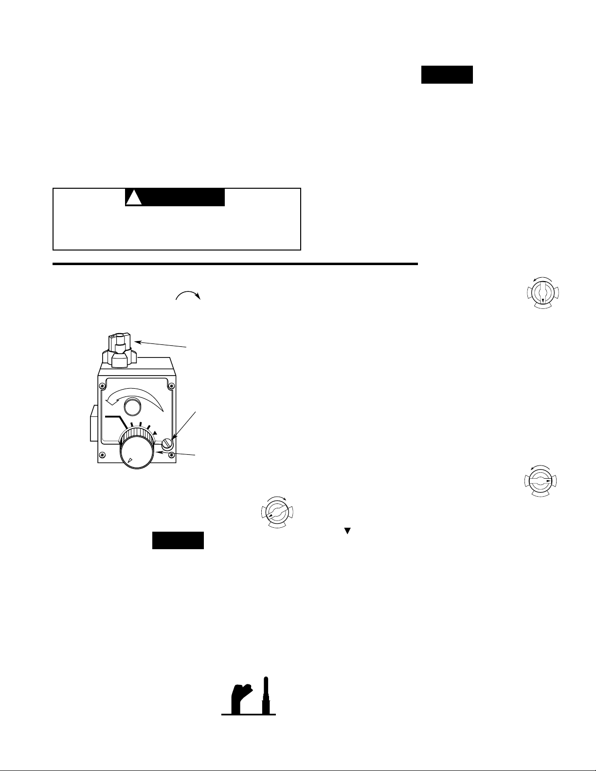
WATER
TEMPERATURE
DIAL
Figure 2. Gas Control Knob, Pilot Adjust
and Water Temperature Dial
GAS
CONTROL
KNOB
PILOT ADJUST
COVER SCREW
HOT
HOTTER
A
B
C
VERY
HOT
O
N
O
F
F
P
I
L
O
T
O
N
O
F
F
P
I
L
O
T
WARNING
!
O
N
O
F
F
P
I
L
O
T
PILOT
BURNER THERMO-
COUPLE