MicroSys miriac SBC-T104 Series User manual

miriac SBC-T104x
User Manual (CRX05 Revision 2 + Revision 3)
V 2.3

Table of Contents
miriac SBC-T104x User Manual
V 2.3
2/71
© MicroSys Electronics GmbH 2017
Table of Contents
1General Notes..............................................4
1.1 Warranty........................................................4
1.2 Links..............................................................4
1.3 Liability..........................................................4
1.4 Offer to Provide Source Code of Certain
Software........................................................5
1.5 Symbols, Conventions and Abbreviations.....6
1.5.1 Symbols ........................................................6
1.5.2 Conventions ..................................................6
2Introduction .................................................7
2.1 Safety and Handling Precautions..................7
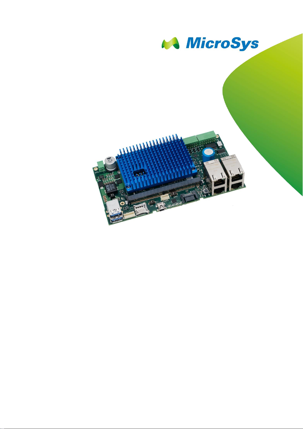
2.2 Short Description...........................................8
2.3 Shipping List..................................................8
2.4 Feature Changelist for HW Revisions ...........8
2.4.1 Changes from revision 2 to revision 3...........8
2.4.2 Feature Changelist for HW Revision 2 ..........9
2.5 Functional Coverage...................................10
3Quick Start Guide......................................11
3.1 Prerequisites ...............................................11
3.1.1 Minimum Requirements ..............................11
3.1.2 Recommended Items..................................11
3.2 Board Preparation and Power-Up ...............12
3.3 Operation ....................................................13
3.3.1 U-Boot Startup.............................................13
3.3.2 Linux............................................................14
4System Description...................................15
4.1 Block Diagram.............................................15
4.2 Feature Overview........................................16
4.3 Mechanical Dimensions ..............................18
4.3.1 MPX-T1042.................................................18
4.3.2 SBC-T104x..................................................19
4.4 Connector Layout –Top..............................20
4.5 Connector Layout –Bottom.........................21
4.6 Power Supply..............................................22
4.6.1 Input Supply Rating.....................................22
4.6.2 Input Power Connector................................22
4.6.3 Power Supply Structure...............................22
4.6.4 RTC Backup Battery....................................23
4.6.5 Current Measurement .................................24
4.6.6 Fuses ..........................................................24
5System Core, Boot Configuration and
On-Board Memory.....................................25
5.1 Processor NXP T1042.................................25
5.2 JTAG Chain.................................................25
5.3 Reset Structure ...........................................25
5.4 Clock Distribution.........................................27
5.5 Boot Configuration.......................................29
5.6 NAND Flash.................................................30
5.7 SPI Flash.....................................................31
5.8 I²C Bus.........................................................32
5.8.1 I2C-1............................................................32
5.8.2 I2C-2............................................................33
6Peripherals.................................................35
6.1 Connector References.................................35
6.2 Module Connector.......................................36
6.3 LAN Connections.........................................36
6.3.1 Port 1...........................................................37
6.3.2 Port 2...........................................................37
6.3.3 Port 3...........................................................38
6.3.4 Port 4...........................................................38
6.4 PCIe Connections........................................39
6.4.1 Mini-PCIe Slot..............................................39
6.4.2 Mini-PCIe Slot / mSATA Slot.......................41
6.4.3 PCIe Extension Connector 1 .......................43
6.4.4 PCIe Extension Connector 2 .......................44
6.4.5 PCIe with external clock ..............................45
6.5 SATA...........................................................46
6.6 MicroSD Card Slot.......................................47
6.7 USB.............................................................48
6.7.1 USB1...........................................................48
6.7.2 USB2...........................................................49
6.7.3 USB3...........................................................50
6.8 UART...........................................................51
6.9 MCU Connector...........................................52
6.10 JTAG Connector..........................................53
6.10.1 JTAG on Revision R3..................................53
6.10.2 JTAG on Revision R2..................................54
6.11 Aurora Connectors (optional).......................55
6.12 General Purpose Inputs / Outputs...............56
6.13 Fan Connector.............................................58
6.14 Smart Card Connector.................................59
6.15 emBRICK Connector...................................60
7Switches, Buttons and Jumpers ..............61
7.1 Boot Device Switch......................................61
7.2 Board Configuration Switch.........................62
7.3 PCIe selection: root complex / endpoint......62
7.4 Reset Button................................................63
8LEDs ...........................................................64
8.1 RJ45 LEDs ..................................................64

Table of Contents
miriac SBC-T104x User Manual
V 2.3
3/71
© MicroSys Electronics GmbH 2017
8.2 Power And Reset LEDs...............................65
8.3 RGB LEDs...................................................66
9Software.....................................................67
9.1 U-Boot.........................................................67
9.2 Operating System Support..........................67
9.3 Flash Layout................................................67
9.3.1 NAND Flash ................................................67
9.3.2 SD Card ......................................................67
9.3.3 SPI Flash.....................................................67
10 Appendix....................................................68
10.1 Acronyms.....................................................68
10.2 Table of Figures...........................................69
10.3 Table of Tables............................................69
11 History........................................................71

General Notes 1
miriac SBC-T104x User Manual
V 2.3
4/71
© MicroSys Electronics GmbH 2017
1 General Notes
Copyright MicroSys Electronics GmbH, January 2017
All rights reserved. All rights in any information which appears in this document
belong to MicroSys Electronics GmbH or our licensors. You may copy the
information in this manual for your personal, non-commercial use.
Copyrighted products are not explicitly indicated in this manual. The absence of the
copyright (©) and trademark (TM or ®) symbols does not imply that a product is not
protected. Additionally, registered patents and trademarks are similarly not
expressly indicated in this manual.
1.1 Warranty
To the extent permissible by applicable law all information in this document is
provided without warranty of any kind, whether expressed or implied, including but
not limited to any implied warranty of satisfactory quality or fitness for a particular
purpose, or of non-infringement of any third party’s rights. We try to keep this
document accurate and up-to-date but we do not make any warranty or
representation about such matters. In particular we assume no liability or
responsibility for any errors or omissions in this document.
MicroSys Electronics GmbH neither gives any guarantee nor accepts any liability
whatsoever for consequential damages resulting from the use of this manual or its
associated product.
MicroSys Electronics GmbH further reserves the right to alter the layout and/or
design of the hardware without prior notification and accepts no liability for doing
so.
1.2 Links
We make no warranty about any other sites that are linked to or from this
document, whether we authorise such links or not.
1.3 Liability
To the extent permissible by applicable law, in no circumstance, including (but not
limited to) negligence, shall we be liable for your reliance on any information in this
document, nor shall we be liable for any direct, incidental, special, consequential,
indirect or punitive damages nor any loss of profit that result from the use of, or the
inability to use, this document or any material on any site linked to this document
even if we have been advised of the possibility of such damage. In no event shall
our liability to you for all damages, losses and causes of action whatsoever,
whether in contract, tort (including but not limited to negligence) or otherwise
exceed the amount, if any, paid by you to us for gaining access to this document.
MicroSys Electronics GmbH
Muehlweg 1
D-82054 Sauerlach
Germany
Phone: +49 8104 801-0
Fax: +49 8104 801-110

General Notes 1
miriac SBC-T104x User Manual
V 2.3
5/71
© MicroSys Electronics GmbH 2017
1.4 Offer to Provide Source Code of Certain
Software
This product contains copyrighted software that is licensed under the General
Public License (“GPL”) and under the Lesser General Public License Version
(“LGPL”). The GPL and LGPL licensed code in this product is distributed without
any warranty. Copies of these licenses are included in this product.
You may obtain the complete corresponding source code (as defined in the GPL)
for the GPL Software, and/or the complete corresponding source code of the LGPL
Software (with the complete machine-readable “work that uses the Library”) for a
period of three years after our last shipment of the product including the GPL
Software and/or LGPL Software, which will be no earlier than December 1, 2010,
for the cost of reproduction and shipment, which is dependent on the preferred
carrier and the location where you want to have it shipped to, by sending a request
to:
MicroSys Electronics GmbH
Muehlweg 1
D-82054 Sauerlach
Germany
In your request please provide the product name and version for which you wish to
obtain the corresponding source code and your contact details so that we can
coordinate the terms and cost of shipment with you.
The source code will be distributed WITHOUT ANY WARRANTY and licensed
under the same license as the corresponding binary/object code.
This offer is valid to anyone in receipt of this information.
MicroSys Electronics GmbH is eager to duly provide complete source code as
required under various Free Open Source Software licenses. If however you
encounter any problems in obtaining the full corresponding source code we would
be much obliged if you give us a notification to the email address
gpl@microsys.de, stating the product and describing the problem (please do NOT
send large attachments such as source code archives etc to this email address)

General Notes 1
miriac SBC-T104x User Manual
V 2.3
6/71
© MicroSys Electronics GmbH 2017
1.5 Symbols, Conventions and Abbreviations
1.5.1 Symbols
Throughout this document, the following symbols will be used:
Information marked with this symbol MUST be
obeyed to avoid the risk of severe injury, health
danger, or major destruction of the unit and its
environment
Information marked with this symbol MUST be
obeyed to avoid the risk of possible injury,
permanent damage or malfunction of the unit.
Information marked with this symbol gives important
hints upon details of this manual, or in order to get
the best use out of the product and its features.
Table 1-1 Symbols
1.5.2 Conventions
Symbol
explanation
#
denotes a low active signal
←
denotes the signal flow in the shown direction
→
denotes the signal flow in the shown direction
↔
denotes the signal flow in both directions
→
denotes the signal flow in the shown direction with additional logic /
additional ICs in the signal path
I/O
denotes a bidirectional pin
Input
denotes an input pin
matched
denotes the according signal to be routed impedance controlled and
length matched
Output
denotes an output pin
Pin 1
refers to the numeric pin of a component package
Pin a1
refers to the array position of a pin within a component package
XXX-
denotes the negative signal of a differential pair
XXX+
denotes the positive signal of a differential pair
XXX
denotes an optional not mounted or fitted part
Table 1-2 Conventions

Introduction 2
miriac SBC-T104x User Manual
V 2.3
7/71
© MicroSys Electronics GmbH 2017
2 Introduction
Thank you for choosing the MicroSys SBC-T104x Single Board Computer system.
This manual should help you to get the best performance and details out all of its
features.
2.1 Safety and Handling Precautions
ALWAYS use the correct type and polarity of the power supply!
DO NOT exceed the rated maximum values for the power
supply! This may result in severe permanent damage to the
unit, as well as possible serious injury.
ALWAYS keep the unit dry, clean and free of foreign objects.
Otherwise, irreparable damage may occur.
Parts of the unit may become hot during operation. Take care
not to touch any parts of the circuitry during operation to avoid
burns, and operate the unit in a well-ventilated location.
Provide an appropriate cooling solution as required.
ALWAYS take care of ESD-safe handling!
Many pins on external connectors are directly connected to the
CPU or other ESD sensitive devices.
Make or break ANY connections ONLY while the unit is
switched OFF.
Otherwise, permanent damage to the unit may occur, which is
not covered by warranty.
There is no separate SHIELD connection.
All the metal sheaths of shielded connectors are connected to
GND.
Also, all mounting holes of the carrier board are connected to
GND.
The module’s mounting holes are not connected to GND
Take this into account when handling and mounting the unit.
Table 2-1 Safety and Handling Precautions

Introduction 2
miriac SBC-T104x User Manual
V 2.3
8/71
© MicroSys Electronics GmbH 2017
2.2 Short Description
The SBC-T104x is a small computer system consisting of
■the MPX-T104x module, based on NXP’s T104x Multicore Communications
Processors
■and the CRX05 carrier board.
It targets both
■evaluation of the respective MPX-T104x SOM
■direct usage as an industrial computing solution
This document gives you an overview on the board's connectors and how to take the
first steps on the initial setup.
2.3 Shipping List
The SBC-T104x EvalKit package contains the following items:
■The SBC-T104x system, mounted with cooling solution
■Power Supply 12V DC stabilized / 2 A
■Cable adapter for the power supply
■USB cable type A –mini B
■Micro-SD-Card with U-Boot and root file system
2.4 Feature Changelist for HW Revisions
2.4.1 Changes from revision 2 to revision 3
The revision 3 of the carrier board provides following changes:
■Added SW4 to switch between root complex and endpoint
■Added 2 header for GND interconnection (JP1, JP2)
■Addes buffer to SPI-CLK
■Added possibility to modify board to run with external PCIe-clock, requires
hardwaremodification (default assembled to use internal clock)
■Type of “JTG-connector” changed to JST-BM14B-SRSS-TB

Introduction 2
miriac SBC-T104x User Manual
V 2.3
9/71
© MicroSys Electronics GmbH 2017
2.4.2 Feature Changelist for HW Revision 2
The revision 2 of the carrier board provides new features:
■Added LED driver with 4x RGB LEDs
■Added 12 GPIOs (6x in / 6x out) addressable via I²C
oOutput voltage level maximum 24V (according to the input voltage
of the carrier board)
oInput voltage range 24V maximum
■Added SuperCap for RTC backup battery (CR2032 coin cell as assembly
option still available)
■Added prerequisites for support of emBRICK devices
■Added current shunt for current measurements
■Added optional (by assembly option) support for onboard current
measurements of the CPU module consumption via I²C current sense
amplifier
■Added LAN interrupt support
■Added SMART CARD connector
■Added optional (by assembly option) extension connector (for example for
additional GPIOs or graphic support if provided by the CPU)
■Added mounting holes for the carrierboard
■Added a fan connector
■Added connector labeling (silkscreen) on the PCB
Some features were changed:
■SerDes 6 and SerDes 7 lanes were swapped in order to achieve a wider
functional coverage within the MPX2 module family
oSerDes 6 is now connected to the SATA connector (ST10)
oSerDes 7 is now connected to the mPCIe / mSATA slot (ST7)
■Improved power input section with filters
■Improved mechanical mounting of the CPU module and mPCIe/ mSATA
cards
■Replaced PCIe x1 edge card connector with second PCIe extension
connector

Introduction 2
miriac SBC-T104x User Manual
V 2.3
10/71
© MicroSys Electronics GmbH 2017
2.5 Functional Coverage
The following table shows the coverage achieved by the SBC-T1042 compared to
the features which are available on the carrierboard:
Interfaces provided by CRX05 carrierboard
Interfaces available with the SBC-
T104x
SerDes 0
PCIe
✓
SerDes 1
SGMII
✓
SerDes 2
SGMII
✓
SerDes 3
SGMII
✓
SerDes 4
mPCIe / Aurora
✓
SerDes 5
PCIe
✓
SerDes 6
SATA
✓
SerDes 7
mPCIe / mSATA
✓(mSATA)
RGMII 1
PHY
✓
USB 1
2.0 / 3.0
✓(2.0)
USB 2
2.0 / 3.0
✓(2.0)
SD-Card
1bit / 4 bit & boot device
✓
UART 1
UART to USB
(debug console)
✓
UART 2
TTL only
✓
I²C 1
Multiple devices
✓
I²C 2
Multiple devices
✓
JTAG
Signals on non-standard
connector
✓
Watchdog
Hardware watchdog with
trigger signal from module
✓
RTC backup
Supercap
✓
Manual Reset
Button
✓
Reset LEDs
2x red
✓
Power LED
1x green
✓
Table 2-2 Functional coverage

Quick Start Guide 3
miriac SBC-T104x User Manual
V 2.3
11/71
© MicroSys Electronics GmbH 2017
3 Quick Start Guide
3.1 Prerequisites
Always make sure to handle the SBC-T104x unit ESD-safe!
Otherwise, the unit may suffer permanent damage.
However, do not place the unit directly flat on a metal surface,
as this may result in short circuits and damage to the board.
At first time operation unpack the unit and make sure that is clean and free of visible
damage or foreign objects.
3.1.1 Minimum Requirements
To operate the board, you will at least need the following items:
■an adequate power supply, delivering 12V DC (stabilized) / 2A minimum.
■an USB cable (type A –mini B) adapted to connector ST5
■a serial terminal, such as a PC with an USB port running a terminal Software
(e.g. TeraTerm, HyperTerminal, putty, ckermit...), or else a hardware serial
console. Choose the following parameters:
(a) 115200 Bd
(b) 8 Data bits
(c) No parity
(d) 1 Stop Bit
3.1.2 Recommended Items
The following items are not absolutely necessary, but strongly recommended for
practical operation and development purposes:
■Network connection via Port1 to your local network installation
■TFTP server available for downloading within the network (Hint: may run on the
same PC as the serial Terminal)
■SATA HDD/SSD and/or SD card as mass storage and/or boot media

Quick Start Guide 3
miriac SBC-T104x User Manual
V 2.3
12/71
© MicroSys Electronics GmbH 2017
3.2 Board Preparation and Power-Up
■Make sure the switches SW1 and SW2 are set properly in order to select the
correct boot source and board configuration
■The board comes preconfigured to boot correctly on arrival.
■Connect the mini USB cable to ST5.
■Connect other peripherals (USB, LAN, SATA, ...) as far as intended.
■Connect the power line to the ST3 connector, while the power supply is still
switched off.
■Switch on the power.
Figure 3-1 System setup example (LAN port 1)

Quick Start Guide 3
miriac SBC-T104x User Manual
V 2.3
13/71
© MicroSys Electronics GmbH 2017
3.3 Operation
After Power-up, the green LED on the module should light up
and any red LED should be off.
IF NOT, DISCONNECT THE UNIT FROM POWER AND CHECK
FOR FAULTS!
3.3.1 U-Boot Startup
When power is supplied the system will start.
On startup, U-Boot will come up similar to the following:
The exact output may vary, depending on U-Boot and MPX-T104x module versions in
use.
Initializing....using SPD
DDR: failed to read SPD from address 81
SPD error on controller 0! Trying fallback to raw timing cal-
culation
U-Boot 2016.07 (Apr 12 2017 - 14:07:42 +0200)
CPU0: T1042E, Version: 1.1, (0x85280211)
Core: e5500, Version: 2.1, (0x80241021)
Clock Configuration:
CPU0:1200 MHz, CPU1:1200 MHz, CPU2:1200 MHz, CPU3:1200
MHz,
CCB:500 MHz,
DDR:800 MHz (1600 MT/s data rate) (Asynchronous),
IFC:125 MHz
QE:250 MHz
FMAN1: 500 MHz
QMAN: 250 MHz
PME: 250 MHz
L1: D-cache 32 KiB enabled
I-cache 32 KiB enabled
Reset Configuration Word (RCW):
00000000: 0a100018 0c000000 00000000 11110000
00000010: 86000002 00000002 68040000 21000000
00000020: 00000000 00000000 00000000 000367fc
00000030: 00000200 81fe0a0f 00000000 00000000
Board: MPXT1040
I2C: ready
SPI: ready
DRAM: 2 GiB (DDR4, 64-bit, CL=12, ECC on)
L2: 256 KiB enabled
Corenet Platform Cache: 256 KiB enabled

Quick Start Guide 3
miriac SBC-T104x User Manual
V 2.3
14/71
© MicroSys Electronics GmbH 2017
Using SERDES1 Protocol: 134 (0x86)
NAND: 512 MiB
MMC: FSL_SDHC: 0
PCIe1: Root Complex, no link, regs @ 0xfe240000
PCIe1: Bus 00 - 00
PCIe2: Root Complex, x1 gen1, regs @ 0xfe250000
02:00.0 - 8086:08b3 - Network controller
PCIe2: Bus 01 - 02
PCIe3: Root Complex, no link, regs @ 0xfe260000
PCIe3: Bus 03 - 03
PCIe4: Root Complex, x1 gen1, regs @ 0xfe270000
05:00.0 - 168c:002a - Network controller
PCIe4: Bus 04 - 05
DIU: Switching to monitor DVI @ 1024x768
CH7033 initialized
In: serial
Out: serial
Err: serial
Net: Initializing Fman
MMC read: dev # 0, block # 2080, count 128 ...
Fman1: Uploading microcode version 106.4.14
FM1@DTSEC1, FM1@DTSEC2, FM1@DTSEC3 [PRIME], FM1@DTSEC4
=>
The module does not have a SPD EEPROM.
U-Boot contains memory timing calculation values for the respective module and
memory configuration setup.
3.3.2 Linux
For detailed setup instructions, refer to the text document “linux-4.1.8-mpx1040.txt”
delivered in the "Linux" directory along with the unit!
The text document mentioned here may refer to an older version.

System Description 4
miriac SBC-T104x User Manual
V 2.3
15/71
© MicroSys Electronics GmbH 2017
4 System Description
This section describes all parts of the SBC-T104x system.
4.1 Block Diagram
Figure 4-1 Block Diagram (MPX-T1042 Revision 4 on carrier CRX05 Revision 2)

System Description 4
miriac SBC-T104x User Manual
V 2.3
16/71
© MicroSys Electronics GmbH 2017
4.2 Feature Overview
The SBC-T104x offers the following features:
QorIQ e5500 cores 4xCPU Processor
SDRAM
64-bit DDR4 interface
Default: 2GByte
up to 8GByte
up to 1600MT/s
4 x DDR4 (x16)
single bank
Synchronous Memory
8-bit NAND Flash
Default: 512 MB
up to 2 GByte
Hard Disk Drives
Interface
SATA 2.0
mSATA slot
SATA 2.0
3.0 Gbps SATA
Connector
PCI Express port
2.0 / 5Gbps
Lane x1
Root complex operations
2x PCIe extension
connector
2.0 / 5Gbps
Lane x1
Root complex operations
1x mSata / Mini PCIe
Slot
2.0 / 5Gbps
Lane x1
Root complex operations
1x Mini PCIe Slot
USB
USB 2.0 Phy
USB connector type A
USB 2.0 Phy
USB connector type A
Expansion Cards
MMC/SD/SDIO
micro SD card holder
Serial Interfaces
UART1
Converted to USB
(FT232),
Available on USB
connector type mini B
UART2
4-wire
Extension Port
LVTTL
I2C
I2C-1
400 kbps
Connected Devices:
LM95245
Temperature Sensor
AT24C128C
EEPROM
BR24G128NUX-3
EEPROM
RX-8803
RTC
IDT6V49205B
Clock Generator
TLC59116
RGB LED Driver

System Description 4
miriac SBC-T104x User Manual
V 2.3
17/71
© MicroSys Electronics GmbH 2017
QorIQ e5500 cores 4xCPU Processor
MAX7325
GPIO Port Expander
I2C-2
400 kbps
Connected Devices:
SC18IS602BIPW
I2C-to-SPI Bridge
MAX9611AUB
Current monitor
TCA9544APWR
I²C Multiplexer
Gigabit Ethernet
Controller
RGMII
10/100/1000 Mbps
SGMII
10/100/1000 Mbps
SGMII
10/100/1000 Mbps
SGMII
10/100/1000 Mbps
System JTAG
Controller
JTAG
Different connector on
CRX05-R2 and R3
Power Management
Primary Supply
LM25116MH
Input:
9-30V DC
Output:
5V DC / peak 8A
Backup Supply
(RTC backup)
Supercap
Table 4-1 Feature Overview

System Description 4
miriac SBC-T104x User Manual
V 2.3
18/71
© MicroSys Electronics GmbH 2017
4.3 Mechanical Dimensions
4.3.1 MPX-T1042
The following drawing shows the mechanical outline of the MPX-T1042 module
that is plugged in the CRX05 carrier board.
This drawing is not to scale.
For 3D data files please contact MicroSys.
Figure 4-2 Mechanical Dimensions Modul

System Description 4
miriac SBC-T104x User Manual
V 2.3
19/71
© MicroSys Electronics GmbH 2017
4.3.2 SBC-T104x
The following drawing shows the mechanical outline of the SBC-T104x assembly.
This drawing is not to scale.
For 3D data files please contact MicroSys.
Figure 4-3 SBC-T1042 Mechanical Dimensions

System Description 4
miriac SBC-T104x User Manual
V 2.3
20/71
© MicroSys Electronics GmbH 2017
4.4 Connector Layout – Top
Figure 4-4 Top connectors
This manual suits for next models
1
Table of contents
Other MicroSys Motherboard manuals