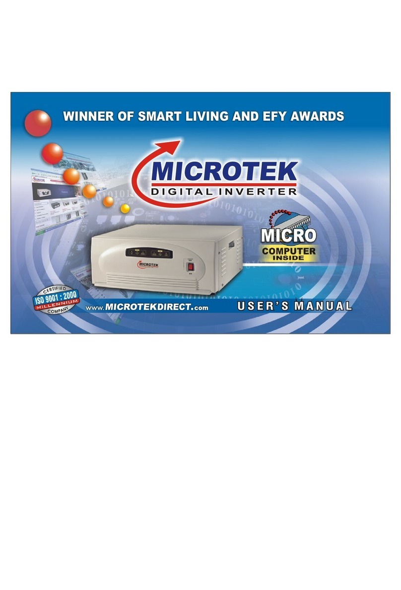
Microtek SineWave UPS EB User manual

U S E R’S M A N U AL

TABLE OF CONTENTS
AN ISO 9001:2000 COMPANY
Congratulations on selecting Micro Controller
Based MICROTEK Sinewave UPS EB / SWE² &
subsequently joining the family of the millions of
satisfied users of Microtek Products.
Before using this UPS, Please read this manual
carefully to familiarize yourself with all its features,
controls and safetyprecautions.
Enjoy Uninterrupted Power !
The Product - Page 03
Salient Features - Page 03
Front Panel - Page 04
Back Panel - Page 06
Troubleshooting - Page 08
Bypassing the UPS - Page 10
Technical Specifications - Page11
Servicing - Page 12
Warranty - Page 12
Safety Instructions - Page 14
Important - Page 14
Going on Vacations - Page 14

3
SALIENT FEATURES
THE PRODUCT
Sinewave UPS EB / SWE² is a electronic power source which stores the energy in battery/batteries connected to it when the
AC source is present and converts this energy automatically to AC power when the Input AC source fails and automatically
feeds generated AC power to the loads connected & returns to mains when the AC source comes back on the input side.
MICRO CONTROLLER / DSP BASED DIGITAL SINEWAVE UPS EB / SWE² are designed using latest state-of-the-art
Technologyfor Better Performance andHighReliability. TheDigital SinewaveTechnology usedenhancesthe life of the
batteryandminimumefforthastobeputformaintenance.
7MICRO-CONTROLLER / DSP BASED Intelligent Control Design.
7Pure Sine Wave Output.
7PWM Controlled multistage ATM (Automatic Trickle Mode) Charging.
7Display Indications (Status & Fault)
7Smart Overload Sense and Short Circuit Protection
7Easily Serviceable
7Auto Reset Feature
7Mains Input Voltage Range Selection.

7
CHARGE
BATTERY CAPACITY
LOAD
BATTERY
5
FUSE BLOWN
OVERLOAD
+
NORMAL
2
6
4
1
I.LEDIndications
1. NORMAL - Mains ON.
2.BATTERY - Backup ON.
3.CHARGE - Battery Charging.
4.FUSE BLOWN.
5.OVERLOAD - at Output.
6.LOAD - Load Status on Backup Mode.
7.BATTERY CAPACITY / Status.
3
FRONT PANEL- LCM-GRAPHIC LCD DISPLAY MODELS
4

6 4
5
3
2
DISPLAY OF MODELS: UPS SWE² 625 / 875 / 1550
1
DISPLAY OF MODELS: UPS SEB 800 / 1400
FUSE
BLOWN
UPS
BATTERY
OVERLOAD
LOW
MAINS UPS CHARGING
ON ON CHARGED
BATTERY
FAULT
STATUS
I.LEDIndications
1.
Mains ON.
2.
UPS on Backup.
3.
Battery Charging.
LED Continuously Glows
when Charged.
LED Blinks when Battery is
Charging.
4.
Fuse Blown.
5.
UPS Overload.
6.
Battery Low.
6 4
5
3
2
1
5
FRONT PANEL-LED MODELS

6.
(-)Negative Battery Lead.
Incase ofSinewave UPS EB 1400 :24V Batt. Sys.
7.
Slide Switch for Mains Input Voltage Range Selection.
In case of Sinewave UPS EB 800 : 12V Batt. Sys.
5. (+) Positive Battery Lead.
6
5
7
4
180V~260V
Input Voltage
Rang e
100V~300V
N E L
1.
InputTerminalBlockforMainsACinput.
2.
CircuitBreaker(10AmpforSinewaveUPSEB800model,
and15AmpforSinewaveUPSEB1400model.)forMains
overload/Short CircuitProtection.
3.
Output socket for load.
4.
Fuse (10Amp. Slow Blow) for UPS.
EWAVEUPSEB 800/1400
3
BACK PANEL OF MODELS:
SIN
2
1
6
BACK PANEL

5
6
1
4
1.
MainsInput LeadforACinput.
2.
Circuit Breaker (7Amp for UPS SWE² 625 model, 10Amp
for Sinewave UPS SWE² 875 model, and 15 Amp for
Sinewave UPS SWE² 1550 model.) for Mains overload/
Short CircuitProtection.
3.
Output socket for load.
4.
Fuse (10Amp. Slow Blow) for UPS.
5.
(+) Positive Battery Lead.
In case of Sinewave UPS SWE² 625/875 : 12V Batt. Sys.
6.
(-)Negative Battery Lead.
Incase ofSinewave UPS SWE² 1550 :24V Batt. Sys.
7.
Slide Switch for Mains Input Voltage Range Selection.
27BACKPANELOFMODELS:
SINEWAVE UPSSWE² 625/875/ 1550
3
7
BACK PANEL

a) Reduce the load and turn the reset switch on the
front panel ON-OFF-ON.
OVERLOAD
3.
UPSModebutnopower:-
a)
Overload
Overload
Red LED Glows
c)NooutputfromUPS c) Check Circuit Breaker/Glass fuse at the rear.
Please reset the circuit breaker, or if the fuse is
blown, replace it with 10Amp rating fuse. If Circuit
Breaker trips or fuse blows again, call electrician to
checkshortingintheloadwiring.
2. UPS trips frequently at Backupmode. The load is more. Reduce the load and reset the
inverter.
b) Check Glass Fuse at the rear. If blown change it
to 10Amp ratting. If fuse still blows call authorised
service engineer.
FUSE BLOWN
b) Fuse Blown
Mains Fuse Blown
Red LED Glows
BATTERY
a) Dead wall socket. Line AC input connections
areloose/notproper.
+
UPS ON
Green LED Glows
.
Possible Cause / Action Suggested
Problem
1.
Main Supply is Normal but:-
a)
UPSisworkingonbattery
8
TROUBLE SHOOTING
LED
LED
LED
LCM
LCM
LCM

a) Check battery water and charge the battery with mains
minimum for 8-12 hours. If still less backup, get the
batterycheckedupfromauthorisedservicepersonnel.
a)
Check the battery connections and the mains
connections.
b)
Internal problem. Bypass the UPS as explained in
nextsectionandcallauthorisedservicepersonnel.
c)
AC Glass fuse blown. Check the fuse at the rear and
replace ifblown.
4.
Backup timeless.
5.
UPSdoesnotoperate.
c) Checkthewiringandreducetheloadandturnthe reset
switch on the front panel ON-OFF-ON.
OVERLOAD
c) Short Circuit
Overload/Short Ckt.
Red LED Glows
Possible Cause / Action Suggested
b) Battery has discharged. Recharge the battery after
the mains restoration.
Problem
b) Low Battery
Low Battery
Red LED Glows
9
TROUBLE SHOOTING
LED
LED
LCM LCM LCM

3
Fig.2
UPSSWE² 625/875/1550
BACK PANEL OF MODELS:
SINEWAVE
2
1
3
Fig.2
Fig. 1 - Use a two way bypass switch externally &
Simply make it ON to Bypass Mode.
OR
Fig. 2 - Alternatively the UPS can be bypassed by
connecting the O/P plug (which connects the load to the
UPS) directly to the socket on the wall from where the
UPS input has been taken. Care must be taken to
ensure that the UPS-ON SWITCH has been switched
off in order that the battery does not discharge.
To bypass the UPS follow the following steps:
1.
Remove input plug from the wall socket,
2.
Remove output plug from the UPS’s output socket, &
3.
Insert output plug into the wall socket.
3.ToLoad.
2. OutputPlug.
1. InputPlug.
180V~260V
Input Voltage
Range
100V~300V
UPS Mode
Fig.1
N E L
EWAVEUPSEB 800/1400
2SINBACKPANELOFMODELS:
1
Two
Way
Switch
By Pass Mode
10
BYPASSING THE UPS

TECHNICAL
SPECIFICATIONS
NOTE:- Because of a policy of continuous product improvement, the specifications are subject to change without notice.
11
MODEL SINEWAVE UPS EB/SWE²
UPS SEB / MEB 800, 1400
UPS SWE² 625, 875, 1550
Input voltage
100V~300V (Wide input voltage range)
180V~260V (Normal input voltage range)
Output Voltage on Mains mode
Same as input
Output Voltage on UPS mode
210V + 5%
Output frequency on UPS mode
50 Hz + 0.1 Hz
Switching from Mains to UPS
and from UPS to mains
Automatic
Output waveform on mains mode
Same as Input
Output waveform on UPS mode
PURE SINE WAVE
Battery charging current
Constant charging approx 10% of the rated battery current in AH
Charger
Power Factor Controlled Boost Technology
Efficiency
> 80%
> 83%
UPS Overload / UPS short circuit
110% / 300%
UPS Transfer Time
< 15 msec.
Browns out mains voltage
100V + 40V
Technology
MICRO CONTROLLER / DSP BASED DESIGN
Auto Reset Feature
Yes

WARRANTY
12
Intheunlikelyeventofyourfacingproblemthathasnotbeensortedoutbytroubleshooting,kindlycontactyourauthoriseddealer
andgivedetailsoftheproblemalongwiththeserialnumberandthedateofinstallation.Thiswouldenableapromptactiononpart
oftheauthorisedservicepersonnelandcauseminimumdowntime.
Microtek InternationalP.Ltd., warrants eachinstrument to befree fromdefects inmaterials and workmanshipforaperiod ofTwo
yearsafterinitialdelivery.Thisobligationislimitedtoservicinganyinstrumentorpartreturnedtotheauthorisedservicecenterfor
that purpose and to making good any parts thereof which shall, within the warranty period, be returned to the company or
authorised Service center under a written intimation and which to the company's satisfaction be found defective. The company
reservestheright todecideastowhethertherepairworkshouldbecarriedoutinthecompany'sservicecenteroratsiteoratany
otherplace.
The freight incurred for to and fro dispatch will have to be borne by the customer and the transit risk for the material will rest with
thecustomer.
The warranty does not extend to any parts of the instrument which have been subjected to misuse or accident. Further, this
warranty does not extend to any instrument which has been tampered with by any agency not authorized by the company.
The warranty will last for a period of 24 months from the date of initial delivery/dispatch of the instrument if used within its
specifications. The warranty for the replaced components will lapse along with that of the main instrument.
SERVICING

13
WARRANTY
MICROTEK International P.Ltd., reserves the right tomake changes in design and specifications without notice and without any
obligationtoinstallsuchchangesonunitspreviouslysupplied.
InnoeventwillMICROTEKInternationalP.Ltd.,itsdistributors/dealersbeliableforconsequentialdamagesorforanyexpenses
incurred by the buyer or user, due to use or sale of products sold by MICROTEK International P.Ltd., directly or through its
authorisedDistributors/dealersoranythirdparty.
Until superceded otherwise or in contractual form this warranty is made expressly in lieu of all other liabilities and obligations on
part of MICROTEK InternationalP.Ltd.
Title to the Instrument passes to the buyer upon delivery to the common carrier.
POST WARRANTY ANNUAL MAINTENANCE CONTRACT
For Microtek SINEWAVE UPS EB / UPS SWE², Microtek Offers Annual Maintenance Contract to save you from any
inconvenience in case of a product failure. Various options are available in select cities for all models of Microtek
SINEWAVEUPS EB / UPS SWE²:-
For Details, Contact nearest Microtek Branch or e-mail at: power.support@microtekdirect.com

IMPORTANT
GOING ON VACATIONS
14
Always connect the UPS to a two pole, three-wire grounding mains socket. The socket must be connected to appropriate branch
protection (fuse/circuit-breaker). Connection to any other type of socket may result in a shock hazard.
To switch off the UPS output in emergency, use switch on the Front panel. Also disconnect the mains cord and battery wires.
AvoidinstallingtheUPSinopen,excessivelyhumidplaceorwherethereiswater.CaremustbetakentoensurethattheUPSiskeptaway
from heat-emitting appliances such as a heater, blower, oven etc. The unit must also be placed in a manner that it avoids exposure to
sunlight.Theplaceofinstallationshouldbewell-ventilatedandeasilyaccessibleforservicing.
Foreign objectsandwatermustnotentertheUPS.Alwaysensurethatobjectscontainingliquidareavoidedneartheunit.
PlacetheBatteryCompartmentasnearaspossibletotheUPS.
Always Switch Off theUPS and disconnect mains when disconnecting the battery.
In the event of any instrument requiring service at our authorised service centre, the following procedure should be adopted.
1.
The instrument must be securely packed, preferably in its original packing.
2.
The instrument should be despatched on Freight-prepaid basis duly insured.
3.
One of our Service / Sales Executive should be informed of the goods Receipt No. and date of despatch along
with the name of carrier.
4.
The above procedure should only be adopted on the advise of one of our Service / Sales Executive or Dealer.
5.
We reserve the right to charge the consignee for any damage incurred during transit.
1.
Must put the UPS ON/OFF Switch in OFF Position.
Mains Input should remain connected to keep the battery always in charged condition.
Costa Power Industries Pvt Ltd.
201,Sainath Prasad Building,Opp Kasturi Plaza, Station Road,Dombivali - East 421201.
Cell No. 9372217661 / 9820710392
SAFETY INSTRUCTIONS
This manual suits for next models
1
Table of contents
Other Microtek Inverter manuals
Popular Inverter manuals by other brands

MQ Power
MQ Power WHISPERWATT DCA-500SSK Parts and operation manual

SUNGOLD POWER
SUNGOLD POWER SPH8K48SP user manual

KEBCO
KEBCO COMBIVERT F4-F Applications manual

Tripp Lite
Tripp Lite PowerVerter PV700HF owner's manual

PowerWalker
PowerWalker 1-2K user manual

Qcells
Qcells Q.HOME PLUS ESS-G1 3.6 user manual

Zeliox
Zeliox ZEL16-1,2-EU User & installation manual

DGFLOW
DGFLOW DGFIT Series Operator and maintenance manual

Sun Power
Sun Power SPR-X22-360-COM Safety and installation instructions

Delta
Delta M100-212 Operation and installation manual

KICK ASS
KICK ASS KAI700WPD user manual

FRONIUS
FRONIUS Signal Card Operating and installation instructions