2)
PI
Control (set point control option)
aHows
automaticcontrol of delivery
pressure and flow rate of fan, pump and blower.
3)
The upper and lower limit output frequency can
be
preset. When the
output frequency has reached its'upperorlowerlimit,
an
open collector
transistor output is available
10r
external use
in
each case.
(4)
In
case 011ault, a
Form
C contact signal (dry contact) is activated.
(5)
Acceleration and deceleration time can be separately selected within the
range of
0.1
to
300
seconds.
3.
Easy
Start-up
(1)
By
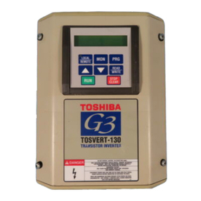
using the monitorfunction, thevarious inverters parameters(invertermode,
inverterstatus, current level, etc.) can be read from the builHn digitalindicator
(4
digit. 7
segment
LED).
(2)
Adjustmentscan
be
madefrom thefront ofthe inverterthrough asmalldooron
the operation panel, and read digitally on the digital LED indicator by
depressing the monitor functions button.
1)
Voltage/Frequency(II
/F)
patterns can be easilyselected theV/Fpattern
rotary selector switch.
o 14 V
/F
patterns
o 2 Energy-saving patterns
2)
By
adjusting the potentiometers (acceleration/deceleration time,
upper/lower limits, etc.), the monitorfunction is automaticallyactivated,
and the set value of the potentiometer is displayed
on
the digital
indicator when selected.
11
an
illegal/abnormal value is set, the built-in
alarm system alerts the operator by flashing the display on the digital
indicator. (e.g.-upper limit is incorrectly set lower than lower limit
setting).
3)
A reset push-button switch is provided
on
the printed circuit board, and
can
be
operated through the small door of the control panel. Reset
terminals are also provided for external reset (dry contact).
4.
Diagnostic
and
Protection
feature
(1)
In
an
instantaneous powerfailure, the inverter operates continuously ifpower
recovers within 30 msec.
(2)
Grounding fault protection is assured
as
a standard function (optional
in
Foreign models)
(3)
Standard protectivefunctions also includestall prevention, overcurrent, over-
load, short-circuit, overvoltage, undervoltage. overheat and internal fusing.
(4)
As
anotherstandard function, a current limit circuit is included which limitsthe
load current automatically at the time of overcurrent.
(5)
A voltage limit circuit is also provided standardized for automatic prevention
over voltage on the
DC
voltage
in
the event of overhauling loads with rapid
deceleration times.
(6)
In
the event of fault, thecause
of
the fault flickers onthe digital LED indicator.
Also, the monitor function allows you to read out the inverter status from
memory for diagnosis of the fault.
(7)
Acharge lamp LED is provided to indicate that the main DC capacitor bankis
charged.
2-2
