Tigo TS4-F User manual

Installation Manual
TS4-F and TS4-R-F, RSS Transmitter

IMPORTANT SAFETY INSTRUCTIONS
LETHAL VOLTAGE MAY BE PRESENT IN ANY PV INSTALLATION
SAVE THESE INSTRUCTIONS
•This manual contains important instructions for installation and maintenance of the Tigo Energy®
product models TS4-F, TS4-R-F, and the RSS Transmitter.
•Risk of electric shock, do not remove cover, disassemble, or repair, no user serviceable parts inside.
Refer servicing to qualified service personnel.
•Before installing or using the Tigo Energy® System, please read all instructions and warning markings
on the Tigo Energy products, appropriate sections of your inverter manual, photovoltaic (PV)
module installation manual, and other available safety guides.
•Failure to adhere to these instructions may result in injury or death, damage to the system or voiding
the factory warranty.
•To reduce risk of fire and shock hazard, install this device with strict adherence to National Electric
Code (NEC) ANSI/NFPA 70 and/or local electrical codes. When the photovoltaic array is exposed to
their output voltage may be as high as the PV module open circuit voltage (VOC) when connected
to the module. The installer should use the same caution when handling electrical cables from a PV
module with or without the TS4 units attached.
•Installation must be performed by trained professionals only. Tigo Energy does not assume liability for
loss or damage resulting from improper handling, installation, or misuse of products.
•Remove all metallic jewelry prior to installing the Tigo Energy TS4 units to reduce the risk of
contacting live circuitry. Do not attempt to install in inclement weather.
•Do not operate the Tigo Energy TS4 units if they have been physically damaged. Check existing
cables and connectors, ensuring they are in good condition and appropriate in rating. Do not
operate Tigo Energy TS4 units with damaged or substandard wiring or connectors. Tigo Energy TS4
units must be mounted on the high end of the PV module backsheet or racking system, and in any
case above ground.
•Do not connect or disconnect under load. Turning off the Inverter and/or the Tigo Energy products
may not reduce this risk. Internal capacitors within the inverter can remain charged for several
minutes after disconnecting all power sources. Verify capacitors have discharged by measuring
voltage across inverter terminals prior to disconnecting wiring if service is required.
•
The transmitter control power supply MUST be on the same AC branch circuit
as the inverter to meet rapid shutdown requirements.

TABLE OF CONTENTS
1. System Overview
1. Rapid Shutdown System
2. TS4 Fire Safety Products
3. System Diagram
1. System Overview: TS4-F
2. System Overview: TS4-R-F
2. MLPE Installation
1. RSS Installation Notes
2. TS4-F Installation
3. TS4-R-F Installation
3. RSS Transmitter Installation
1. Single RSS Core
1. RSS Transmitter Installation
2. RSS Transmitter Wiring
3. RSS Transmitter Grounding
2. Dual RSS Core
1. RSS Transmitter Installation
2. RSS Transmitter Wiring
3. RSS Transmitter Grounding
4. Appendix
1. Product Specifications
1. TS4-F and TS4-R-F Technical
2. TS4-F and TS4-R-F Mechanical
3. RSS Transmitter Technical
4. RSS Transmitter Outdoor Kit Technical
2. Testing Rapid Shutdown
3. Troubleshooting
4. Conduit Drilling Guide
5. Contact Information
6. Ordering Information

Module Level Power Electronics:
Transmitter:
1.1 RAPID SHUTDOWN SYSTEM
TS4-F, TS4-R-F
•NEC 2017 690.12 Rapid shutdown
compliant
•Module-level deactivation
•PLC SunSpec-compliant communication
•Plug & play, no configuration required
RSS Transmitter
•Rapid Shutdown System transmitter for
rapid shutdown activation of TS4-F or
TS4-R-F units
•The external device that provides a
keep-alive signal to the PVRSE device
via Power Line Communication.
1.2 TS4 FIRE SAFETY PRODUCTS
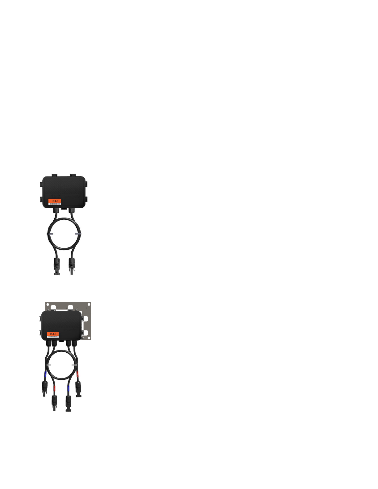
TS4-F
•Module electronics are contained in the
junction box, installed at the PV module
factory.
•Connected in series like regular modules
•No additional wiring connections to make
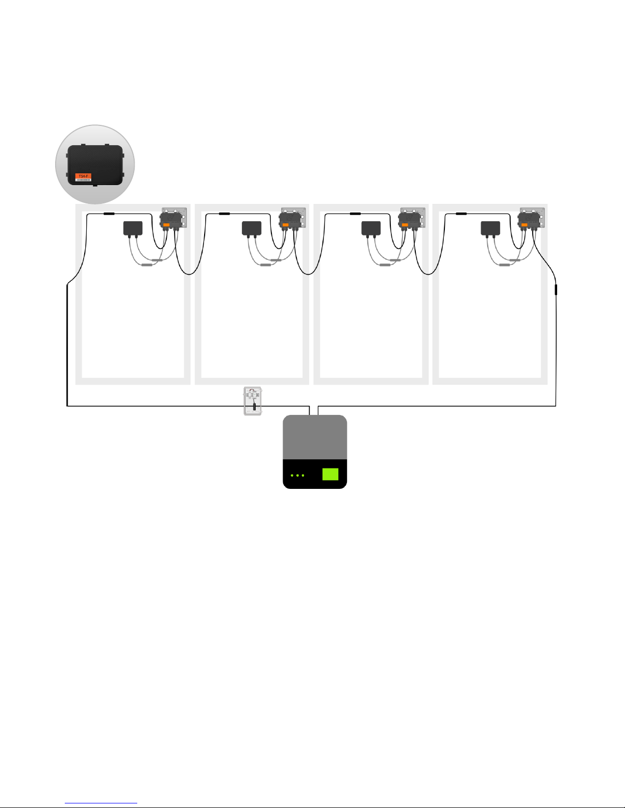
TS4-R-F
•Bracket clips to module frame without tools
•TS4-R-F outputs are connected in series to
form a string
•No additional grounding required
•NEC 2017 690.12 Rapid shutdown compliant
•Module-level deactivation
•PLC SunSpec-compliant communication
•Plug & play, no configuration required

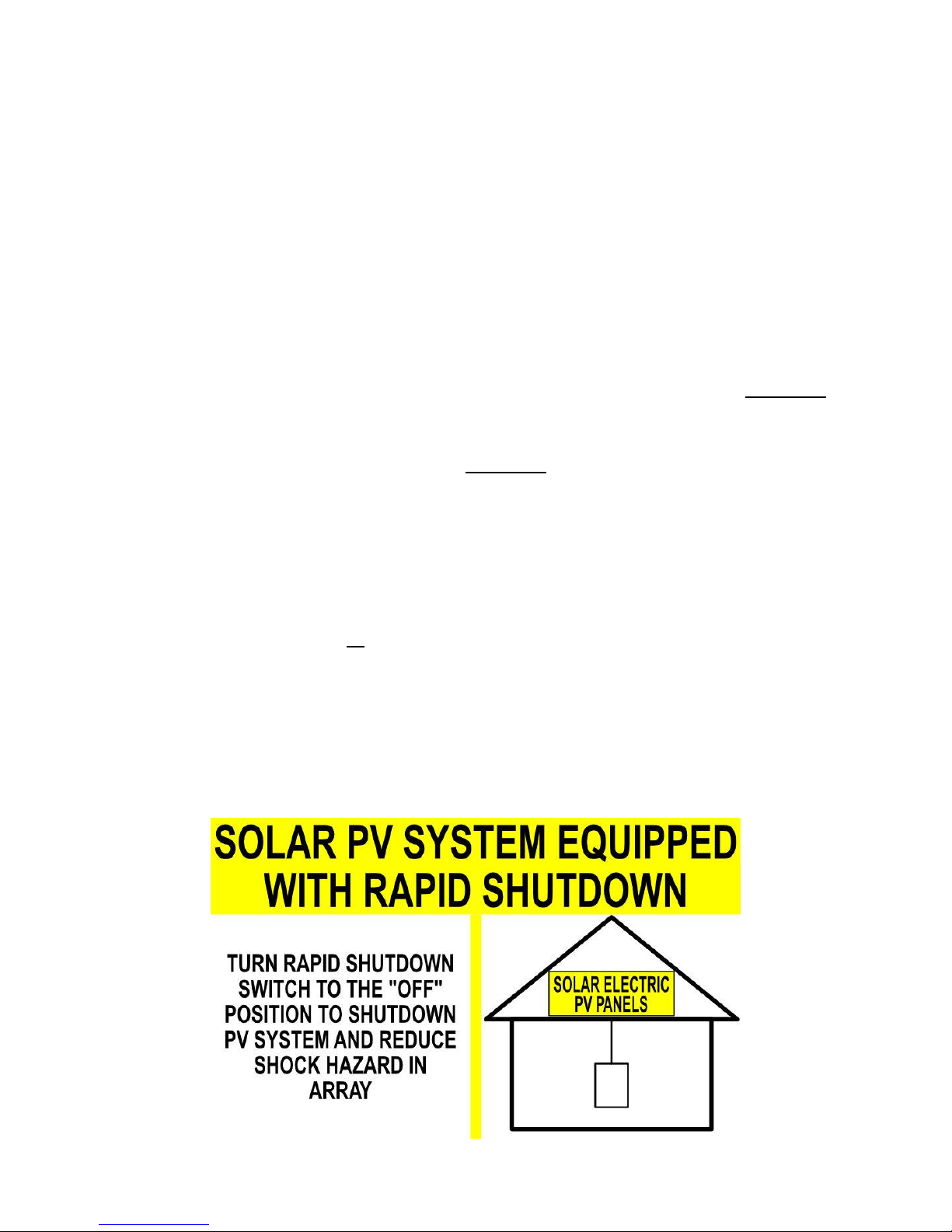
1.3.1 SYSTEM OVERVIEW: TS4-F
Inverter
TS4 Smart Module
Powered by Tigo
The TS4-F requires a Tigo RSS Transmitter or inverter with built-in transmitter for
operation.
The Tigo RSS Transmitter is installed in line with a solar PV inverter, as shown,
and can be installed inside the inverter or external to it.
Method of Operation
TS4-F and TS4-R-F units start in the OFF position and measure 0.6V at the output.
When power is supplied to the RSS Transmitter, the TS4-F/TS4-R-F units turn ON
and allow full PV module voltage.
-transmitter over
PLC. When power to the transmitter is cut, this keep-alive signal ceases,
sending every TS4-F/TS4-R-F into shutdown mode with output reduced to 0.6V.
RSS Transmitter
1.3.2 SYSTEM OVERVIEW: TS4-R-F
Inverter
TS4-R-F Smart Module
Add-on
Powered by Tigo
•TS4-R mounting is recommended on the upper right as shown, but can be
placed on upper left if needed (due to racking constraints, etc.)
•TS4-R cable glands must not be facing up.
•Allow clearance between PV module and mounting surface for air
circulation around TS4-R.
•Do not drill additional mounting holes in the frame or metal bracket.
RSS Transmitter
Note: connect modules to TS4-R inputs before connecting outputs
2.1 RSS INSTALLATION NOTES
•TS4-F and TS4-R-F are shipped in the OFF position and will
measure 0.6V at the output when the keep-alive signal is not
present.
•Failing to follow the sequence of installation steps may result in
TS4 damage not covered under warranty.
•Connect all TS4-R-F units to their respective modules before
connecting their outputs in series.
•Install all TS4-F or TS4-R-F units before powering on the RSS
Transmitter.
•Never apply an external voltage source to a module or string
equipped with TS4-F/TS4-R-F units.
•If parallel string connections are needed, first connect the TS4-F/TS4-R-F to
the PV modules, then connect all TS4-F/TS4-R-F outputs in series, and finally
pass one side (+ or -) of the homeruns through the PLC transmitter to turn
the system ON.
•Place rapid shutdown system label no more than 1m (3ft) from
initiator (AC disconnect) or service panel containing means of
disconnection if not at same location.
Place Rapid Shutdown System label in proper location.
2.2 TS4-F INSTALLATION
Smart modules with an integrated TS4 Junction box are installed
and connected in series just like standard PV modules.
Connect modules with TS4-F in series before powering on the RSS
Transmitter.

2.3 TS4-R-F INSTALLATION
Connect the long output cables
of the TS4-R-F units in series to
form strings, as you would with
standard PV modules
3
Connect the PV
cables from the
module to the short
leads of the TS4-R-F
2
Mount the TS4-R-F on
the top right corner
of a PV module
1
Standard modules can be equipped with TS4-R-F add-on/retrofit
units as shown above.
Always connect modules to TS4-R inputs before connecting outputs.
Each TS4-R-F must have a PV module connected to its input before connecting the
outputs of TS4-R-F units in series.
To disconnect TS4-R-F from a module, disconnect the TS4-R-F outputs from the string
before disconnecting the TS4-R-F inputs from the module junction box.

Install TS4-F before powering on RSS Transmitter
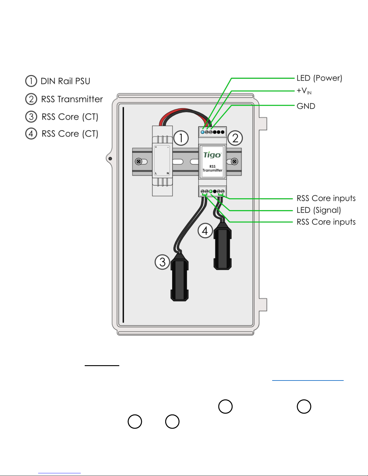
•Drill holes in enclosure for conduit (see appendix for placement guide)
•Mount RSS Transmitter and power supply on DIN rail
•Connect DC leads from power supply (1) to transmitter (2)
•Connect RSS Core (3) to transmitter
3.1.1 RSS TRANSMITTER INSTALLATION –
SINGLE RSS CORE
1 2
3
*Suggested locations for conduit
*
* *

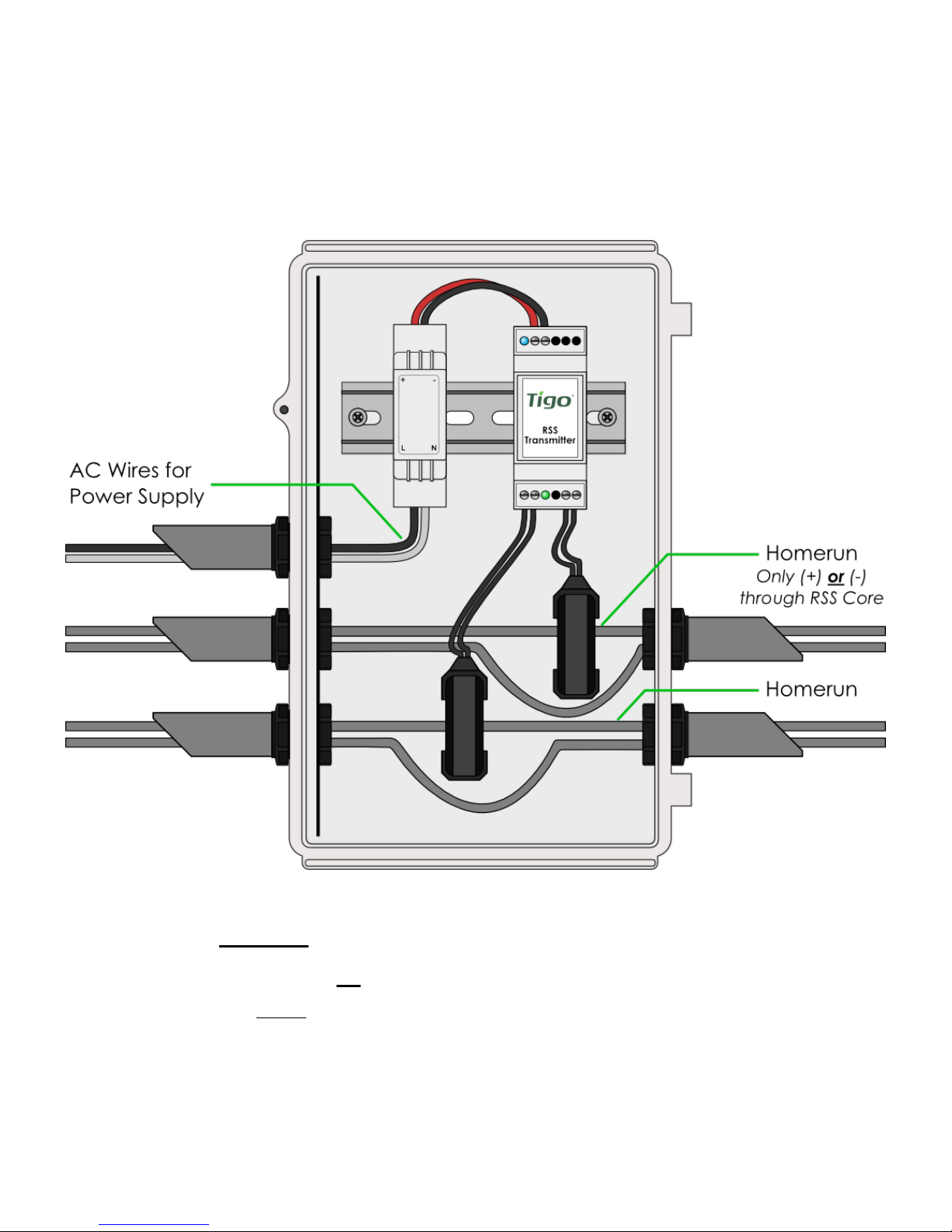
Install TS4-F before powering on RSS Transmitter
•Pass either positive or negative homerun(s) through RSS Core (CT)
•Use the same polarity when passing multiple homeruns through the CT
•Connect wires to AC side of power supply
3.1.2 RSS TRANSMITTER WIRING –
SINGLE RSS CORE
Max number of strings per RSS Core: 10
Max string length: 30 modules
Max current per RSS Core: 100A (in this enclosure)
Max cable length from inverter (+) to inverter (-): 1000ft (300m)

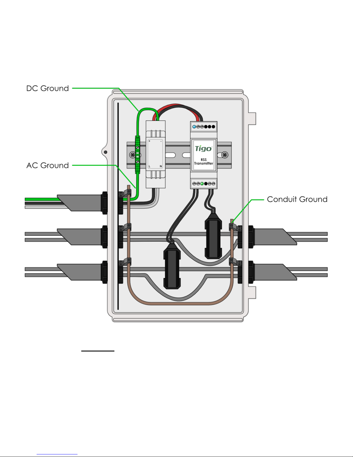
Install TS4-F before powering on RSS Transmitter
•Connect AC and DC ground wires to DIN rail
•Ground all conduit connections
•Turn on AC power to Transmitter power supply to activate
keep-alive signal and energize PV array
3.1.3 RSS TRANSMITTER GROUNDING –
SINGLE RSS CORE
Warning: nonmetallic enclosure does not provide bonding between
conduit connections. Use grounding type bushings and jumper wires.
Install TS4-F before powering on RSS Transmitter
•Drill holes in enclosure for conduit (see appendix for placement guide)
•Mount RSS Transmitter and power supply on DIN rail
•Connect DC leads from power supply (1) to transmitter (2)
•Connect RSS Core (3) and (4) to transmitter
3.2.1 RSS TRANSMITTER INSTALLATION –
DUAL RSS CORE
1 2
3
*Suggested locations for conduit
*
4
*
*
* *
Install TS4-F before powering on RSS Transmitter
•Pass either positive or negative homerun(s) through RSS Core (CT)
•Use the same polarity when passing multiple homeruns through the CT
•Connect wires to AC side of power supply
3.2.2 RSS TRANSMITTER WIRING –
DUAL RSS CORE
Max number of strings per RSS Core: 10
Max string length: 30 modules
Max current per RSS Core: 100A (in this enclosure)
Max cable length from inverter (+) to inverter (-): 1000ft (300m)
Install TS4-F before powering on RSS Transmitter
•Connect AC and DC ground wires to DIN rail
•Ground all conduit connections
•Turn on AC power to Transmitter power supply to activate
keep-alive signal and energize PV array
3.2.3 RSS TRANSMITTER GROUNDING –
DUAL RSS CORE
Warning: nonmetallic enclosure does not provide bonding between
conduit connections. Use grounding type bushings and jumper wires.

APPENDIX
A. Product Specifications
B. Testing Rapid Shutdown
C. Troubleshooting
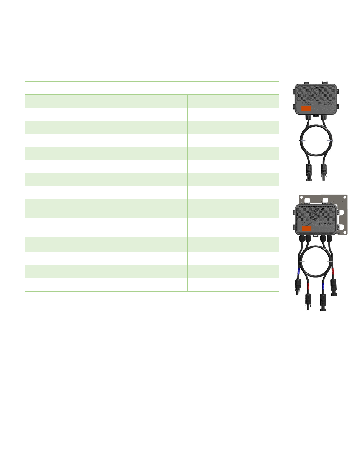
4.1.1 TECHNICAL SPECIFICATIONS –
TS4-F / TS4-R-F
Specify system voltage when ordering (1000V / 1500V) for
appropriate cables & connectors.
Rapid shutdown activation requires RSS Transmitter.
ELECTRICAL RATINGS
FIRE SAFETY
TS4
-F / TS4-R-F
INPUT
Rated DC Input Power
475W
Maximum Input Voltage at Lowest Temperature
90V
Max
Continuous Input Current (IMAX) 12.5A
Maximum V
OC @ STC 75V
Minimum V
MP 16V
OUTPUT
Output Power Range
0 -475W
Output Voltage Range
0 VOC
Communication Type
Power Line
Communication (PLC)
Rapid Shutdown UL Listed
(NEC 2014
& 2017 690.12) Yes
Impedance Matching Capability
No
Output Voltage Limit
No
Maximum System Voltage
1500V
Fuse Rating
20A

4.1.2 MECHANICAL SPECIFICATIONS
–TS4-F / TS4-R-F
ELECTRICAL RATINGS
FIRE SAFETY
TS4
-F / TS4-R-F
MECHANICAL
Operating Temperature Range:
-40°C to +70°C (-40°F to +158°F), RH < 85%
Storage Temperature Range:
-40°C to +70°C (-40°F to +158°F), RH < 60%
Cooling Method
Natural Convection
Dimensions (with cover)
178.5mm x 134mm x 25.5mm
Weight (base and cover)
670g
Outdoor Rating
IP68, NEMA 3R
CABLING
Type
H1Z2Z2-K
Output Length
Standard 1.2m, other lengths on request
Cable Options
1000V rated
1500V rated
Cable Cross
-Section 6.3 ± 0.3mm
Connectors MC4, MC4 compatible
UV Resistance 500hr with UV light between 300-400nm @65C
Maximum String Voltage 1500V UL/IEC1
4.1.3 TECHNICAL SPECIFICATIONS –
RSS TRANSMITTER
ELECTRICAL RATINGS
RSS Transmitter
INPUT
Input Voltage
12VDC
Input Current
1A
Average Supply Power
0.85W
Recommended Power Supply Rating
12VDC and 2A
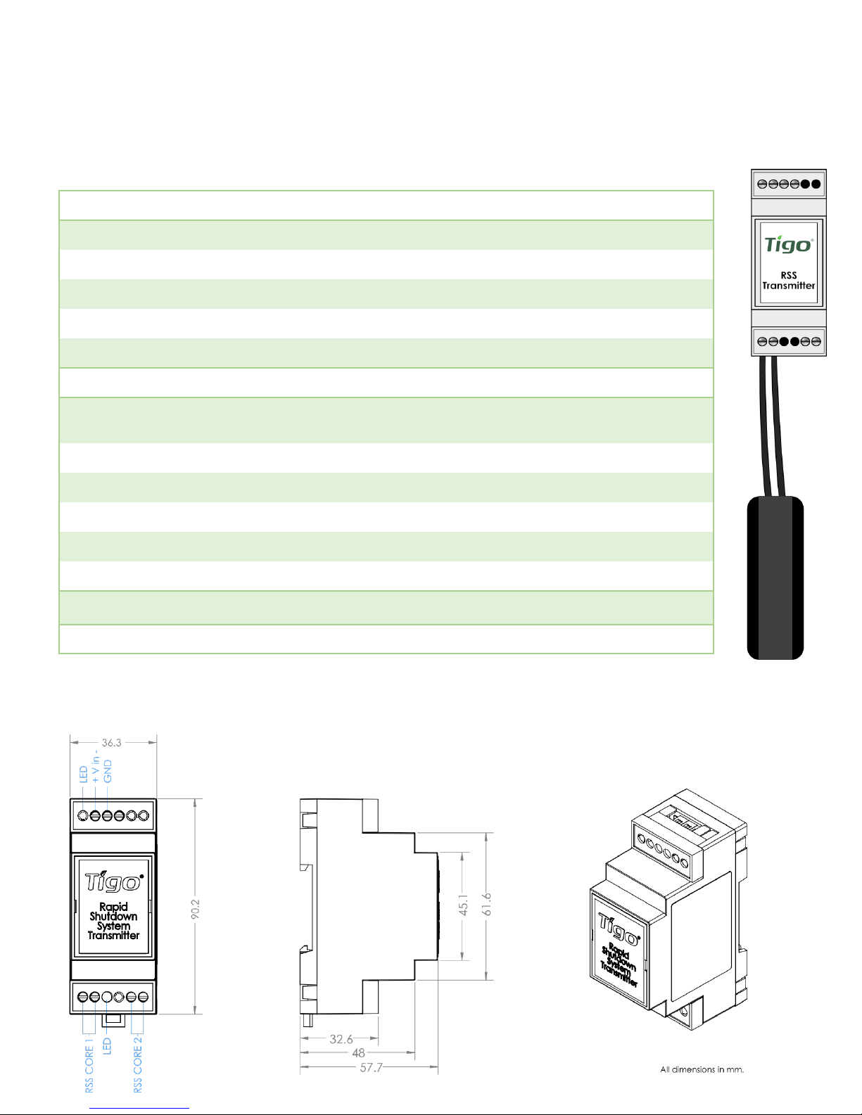
Dimensions (Transmitter only)
90.2mm x 36.3mm x 57.7mm
RSS Core
Max Current
150A per Core
(Single Core: 150A, Dual Core: 300A)
Max MPPT String Voltage
1500VDC
Internal Opening for Wires
27.5mm
Outside Dimensions
59mm
Max Number of Strings per Core
10
Max String Length
30 modules
Environmental
Temperature
-40°C to 85°C
Recommended max. torque 0.79 N/m for wiring
Other manuals for TS4-F
3
This manual suits for next models
2
Table of contents
Other Tigo Inverter manuals

Tigo
Tigo EI User manual

Tigo
Tigo TSI-6K3DTSI-10K3D User manual

Tigo
Tigo TSI-3K1D User manual

Tigo
Tigo TS4-A-O User manual

Tigo
Tigo ENERGY MODULE MAXIMIZER ES Series User guide

Tigo
Tigo EI Inverter User manual

Tigo
Tigo TSS-3PS User manual

Tigo
Tigo TS4-A-2F User manual

Tigo
Tigo EI User manual

Tigo
Tigo TSI-7.6K-US User manual


Popular Inverter manuals by other brands

STEP
STEP ME800 Series user manual

SolarEdge
SolarEdge SE15K-AU installation guide

Generac Power Systems
Generac Power Systems 004988-2 owner's manual

MUND CLIMA
MUND CLIMA serie h5a mupr-h5a Installation and owner's manual

Xantrex
Xantrex PowerHub PH1800 Operator's guide

opti-solar
opti-solar SNMP Manager quick guide


