Microtrol Black Pear RBC-TSI1 User manual
RBC-TSI1
Installation Manual
280818_IM_RBC-TSI1_v2-05
Installation and Operating Instructions
RBC-TSI1 Interface

1
RBC-TSI1 Versatile Interface Installation Manual

2
RBC-TSI1 Versatile Interface Installation Manual
Page
Important................................................................................................................................................................... 3
Agreements for use of this product ........................................................................................................................... 3
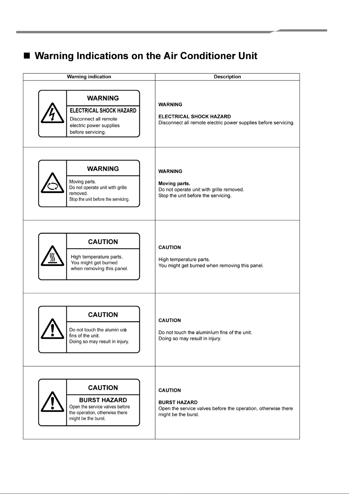
Warning Indications on the Air Conditioner............................................................................................................... 4
Important Information................................................................................................................................................ 5
Product Description................................................................................................................................................... 6
Mechanical Data ....................................................................................................................................................... 7
Wiring Information..................................................................................................................................................... 8
Appendix A: - Definitions........................................................................................................................................... 9
Appendix B: - Operating Modes.............................................................................................................................. 10
B1: Standard Mode ................................................................................................................................................. 10
B2: Pre-Set Slave Unit ............................................................................................................................................ 12
B3: Standard Slave with Local/Restore .................................................................................................................. 13
B4: Duty/Standby .................................................................................................................................................... 14
B5: Eco Timed Fan Mode ....................................................................................................................................... 16
B6: Eco Fan Band Mode......................................................................................................................................... 17
B7: Hotel Controller Mode....................................................................................................................................... 18
B8: VN Unit ............................................................................................................................................................. 19
B9: AHU Mode ........................................................................................................................................................ 21
Appendix C: - Analogue Inputs............................................................................................................................... 23
Appendix D: - Modbus ............................................................................................................................................ 24
Appendix E: - Faults Codes.................................................................................................................................... 27
Appendix F: - LED Information............................................................................................................................... 28
Appendix G: - Configuration Registers ................................................................................................................... 29
Appendix H: - Firmware Upgrade ........................................................................................................................... 32
Appendix J: - Setting the Modbus Slave Address.................................................................................................. 33
Appendix K: - Revision History............................................................................................................................... 37

3
RBC-TSI1 Versatile Interface Installation Manual
!Important
This manual is intended for those who have the required knowledge/Qualifications for electric or control and are in
charge of any of the following:
"Installation of the product
"Design of the control system
"Management of the site
!Agreements for use of this product
(1) Scope of warranty
If a failure occurs in this product as a result of our fault or negligence we will provide replacement or repair of the
product.
We will not be responsible if the fault occurs as a result of any of the following.
"The product was handled or used under conditions/environment that are not specified in this manual.
"The failure was caused by aspects outside of this product.
"The product was altered or repaired by persons other than Toshiba Carrier.
"The product was not used in accordance with its original purpose.
"The cause of the failure was not foreseeable with our scientific and technical levels at the time of shipping.
"The failure is due to a natural calamity, disaster, or the like.
The warranty mentioned here shall cover only this product, and any damage and losses resulting from the failure of
this product shall be excluded from the scope of warranty.
(2) Restrictions of liability
In no event shall we be liable for any special, indirect, or consequential damage arising out of or in connection with the
use of this product.
(3) Conditions for use of this product
"When this product is to be used in combination with other products, the dealer or qualified professional shall
check the applicable standards, specifications, laws, and regulations beforehand. The dealer or qualified
professional shall also verify that this product conforms to the customer’s system, machines, and/or
equipment in which this product is to be used. If the dealer or qualified professional fails to do so, we shall not
be responsible for the conformity of this product.
"When you wish to use this product for any of the following purposes, be sure to consult our sales staff and use
this product with a margin of rating and performance, as well as take appropriate safety measures for safety
circuit, mechanism, etc. that will minimize danger in case of a failure.
•Use this product outdoors or for purposes that may cause latent chemical contamination or electrical
interference or use under conditions/environment that are not specified in this manual.
•Use this product in nuclear power control facilities, incineration facilities, railway/airline/vehicle facilities,
medical equipment, amusement machines, safety devices, and equipment/facilities that are restricted by
administrative organizations and/or respective industries.
•Use this product in systems, machines, or equipment that may pose a danger to human life or properties.
•Use this product in systems or facilities that require high reliability, such as gas/water/electricity supply
systems and non-stop operation systems.
•Use this product for other purposes that require a high level of safety.
"Thoroughly understand and strictly observe all prohibitions and precautions for use stated in this manual to
prevent contingent damage or losses to you or other persons due to improper use of this product.
(4) Changes to specifications
The specifications described in this manual is subject to change for improvement or other reasons without notice.
Contact our sales staff to confirm the latest specifications of this product.
4
RBC-TSI1 Versatile Interface Installation Manual

5
RBC-TSI1 Versatile Interface Installation Manual

6
RBC-TSI1 Versatile Interface Installation Manual
Product Description
The RBC-TSI1 is a versatile interface for Toshiba air conditioning units, offering a wide range of external control
facilities. The unit attaches to the TCC-NET A+B network. The interface is network powered and may be used with or
without a remote controller being present. Up to eight indoor units may be monitored and controlled as a group by a
single RBC-TSI1.
Hardware Interface:
Six analogue control inputs selectable as resistance or 0-10v D.C. Two relay outputs for ‘Run’ and ‘Error’ rated 24v
0.1A
Serial Interface:
RS-485 serial Modbus connection with slave addresses from 1 to 254 and configurable baud rates and parity.
Modbus may be used for monitoring and control or to allow the
operation of up to sixteen units in a ‘Master/Slave’ configuration.
Operating Modes:
Several modes of operation are available including special modes for energy saving and hotel applications.
Modes are selected by a link and bit switches.
AVAILABLE MODES:
1.
Standard operation with the facility to interconnect up to 16 interfaces as a ‘Master/Slave’ group.
(See Appendix B1)
2.
As (1) for VN units
(See Appendix B8)
3.
Preset mode operation.
(See Appendix B2)
4.
Local/Restore mode.
(See Appendix B3)
5.
Duty/Standby operation.
(See Appendix B4)
6.
Eco-1 (Timed Fan).
(See Appendix B5)
7.
Eco-2 (Fan Band).
(See Appendix B6)
8.
Hotel mode.
(See Appendix B7)
9.
AHU Mode
(See Appendix B9)
SPECIFICATION INDOOR INTERFACE
ELECTRICAL
ENVIRONMENTAL
Model
RBC-TSI1
Supply
15V-24V DC, 50mA
Storage Temperature Range
-10°C to 50°C
Power
<1.2VA
Operating Temperature range
0°C to 50°C
Relay
1A, 24VAC max
Humidity Range
0-90% RH non-condensing
1A, 30VDC max
Mechanical
Inputs Voltage Mode
S1..S6 0..10VDC <1mA
Casing
ABS Plastic
Inputs Resistance Mode
S1..S6 5V, 1mA
Dimensions
H90 x W107 x D32 mm
EMC Emissions
EN61000-6-1
Weight
120g
EMC Immunity
EN61000-6-3
Mounting
2 Key Slot or DIN Rail
Connectors
Rising clamp to 0.752mm
Protection
IP30
SPECIFICATION FOR CONNECTION CABLES
INPUT
DESCRIPTION
S1 to S6
Cable Type
2-core shield wires
Screen must be earthed at one end only
Wire size and
max. length
1.0 mm2200m max. (min. 0.5 mm2)
It is recommended that volt-free contacts or switch mechanisms
connected to S4, S5 and S6 have gold plated contacts to ensure low
resistance circuit
Resistances should be within +/-250 ohms of the quoted value. Open circuit is R>200kΩ. Voltages should be within +/- 0.25V of the quoted value.
Open circuit for V<1V. Under open circuit conditions the input will revert to its default value. S1 in resistance mode is designed to be operated using a
linear 10kΩvariable resistance.
7
RBC-TSI1 Versatile Interface Installation Manual
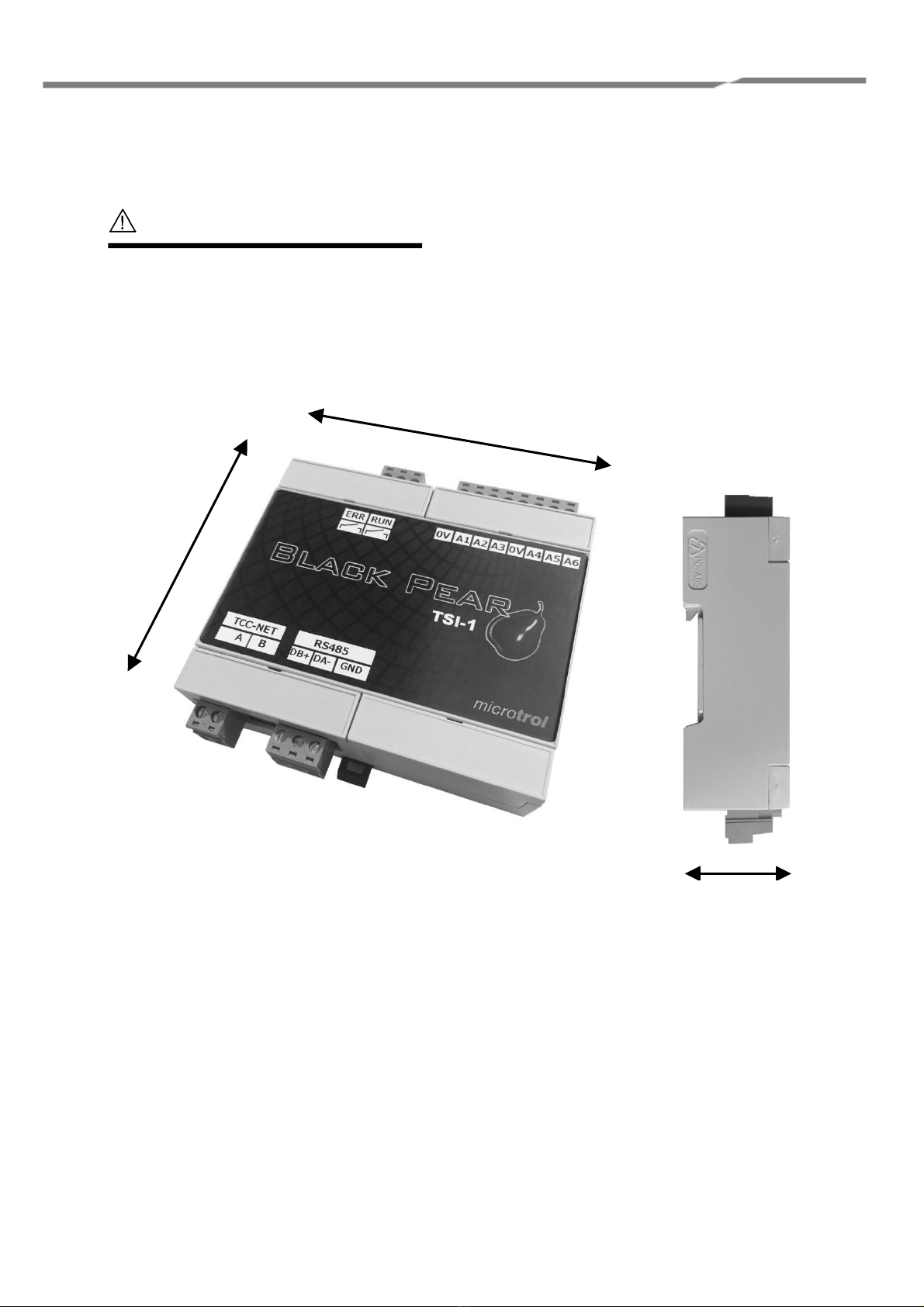
Mechanical Data
107mm
90mm
32mm
CAUTION
#Do not exceed the specified fault relay ratings
#Observe precautions for handling
electrostatic sensitive devices

8
RBC-TSI1 Versatile Interface Installation Manual
Wiring Information
Run Relay
24v 0.1A
Error Relay
24v 0.1A
Analogue
Inputs
Configuration
Switches
Common
RS485
Connect to Toshiba
A/B Network
CAUTION
#All electrical work should be carried out by a competent person
and wiring must be in accordance with the national electrical
installation regulations.
9
RBC-TSI1 Versatile Interface Installation Manual
Appendix A: - Definitions
The following nomenclature is used throughout this document.
Modbus Holding Registers H-nn:
These are the function 3/6/16 registers with offset nn.
They are the same as registers 40000 + nn + 1
Function 3 is used to read the registers
Functions 6 and 16 may be used to send values to them.
Modbus Input Registers I-nn:
These are the function 4 registers with offset nn.
They are the same as registers 30000 + nn + 1
Function 4 is used to read the registers
These registers may not be written to.
e.g. H-15 is equivalent to 400016 and is accessed for read/write
by Function 3/6/ 16 using offset 15.
I-24 is equivalent to 300025 and is accessed for read by Function 4 using offset 24.
Hardware Inputs:-
This means either the analogue inputs A1 to A6 or the internal registers H-51 to H-59, depending which set is selected
by switch S1-6.
The analogue inputs A1 to A6 may be configured as Voltage (0-10v) or Resistance inputs.
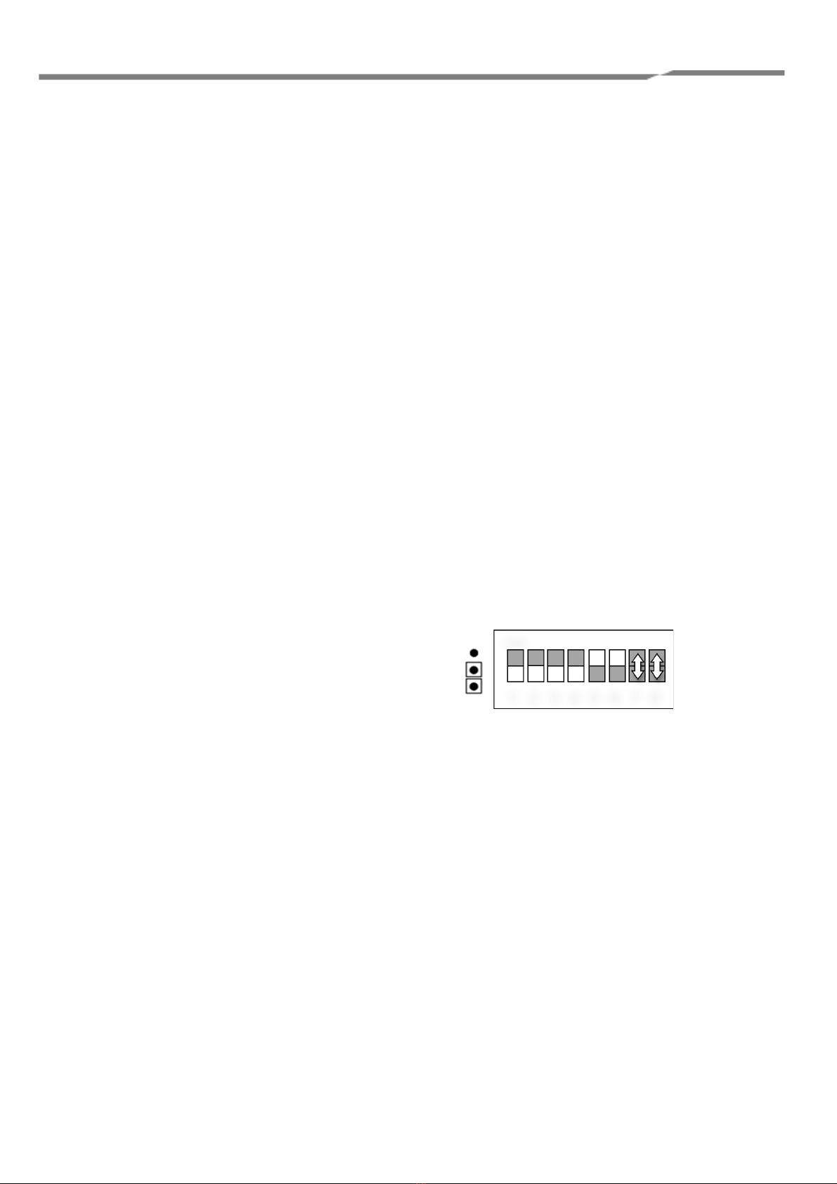
Switch Settings Diagrams:-
The switch setting diagrams in this document use the following convention:
In the diagram opposite:
S1-1 to S1-4 are shown in the OFF position
S1-5 & S1-6 are shown in the ON position
S1-7 & S1-8 are shown as selectable
S2 is shown Unlinked
Selectable switches will have their functions described.
1 2 3 4 5 6 7 8
ON

10
RBC-TSI1 Versatile Interface Installation Manual
Appendix B: - Operating Modes
B1: Standard Mode
Master Unit
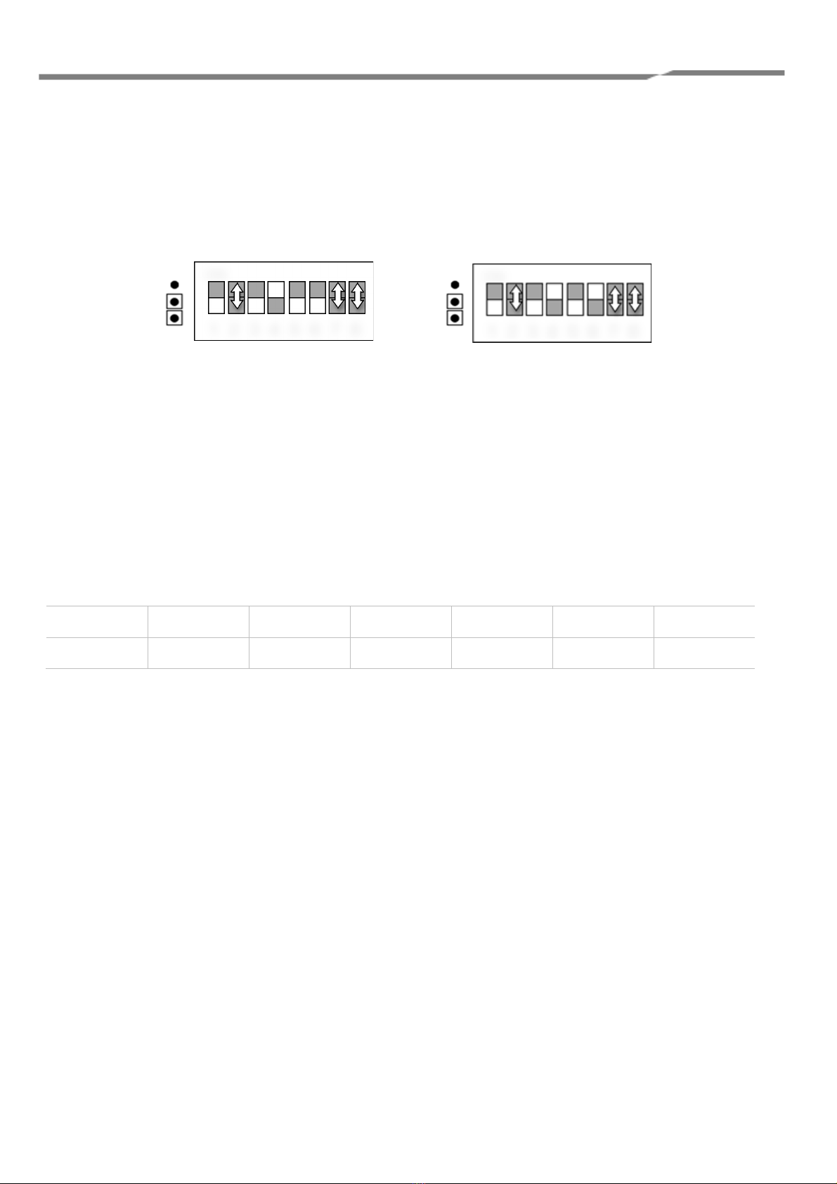
Switch Settings:
S1-2: Voltage or resistance inputs for A1 to A6
OFF = Resistance (for A5 active means linked to 0v)
ON = Voltage (for A5 active means supplied with > 6.5v)
S1-3: Enable sending of parameters to slave units 1 to 15
OFF = Do not send
ON = Send
A standard Master unit will accept hardware inputs from either A1-A6 or H-51 to H-55.
If S1-3 is set On then the unit will periodically send its parameters to standard Slave units with addresses 1 to 15
Input
A1/H-51
A2/H-52
A3/H-53
A4/H-54
A5
A6/H-55
Parameter
Set point
(SP)
Fan Speed
(FS)
Mode
(MD)
Louvre
(AD)
On/Off
(I/O)
Lock
ON
Using A1 to A6
1 2 3 4 5 6 7 8
Using H-51 to H-55 and A5
1 2 3 4 5 6 7 8
ON

11
RBC-TSI1 Versatile Interface Installation Manual
Slave Unit
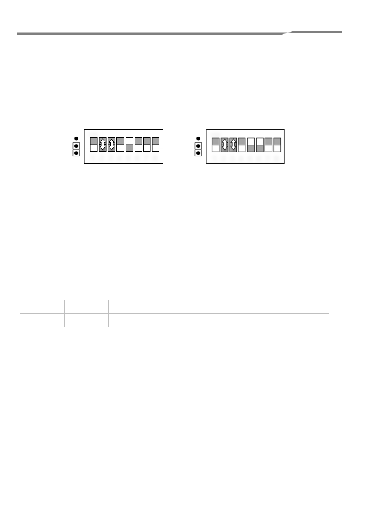
Switch Settings:
S1-2: Voltage or resistance inputs for A1 to A6
OFF = Resistance (for A5 active means linked to 0v)
ON = Voltage (for A5 active means supplied with > 6.5v)
S1-3: Locked Slave/Locked Master
OFF = Locked to Slave Defaults
ON = Locked to Master Defaults
S1- 7 & S1-8: Modbus Address
S1-7 Off S1-8 Off = Invalid for slave unit.
S1-7 Off S1-8 On = 1
S1-7 On S1-8 Don’t Care = Address as set by C5 & C6 (See Appendix J)
A standard Slave unit will accept Hardware Inputs
It will also accept values sent by a Standard Master unit if its address is in the range 1 to 15.
Lock function:
If any parameters are locked using the A6 /H-55 input then these parameters Will be locked to:-
The Hardware Inputs settings on the Slave if S1-3 is Off
The values from the Master if S1-3 is On
Input
A1/H-51
A2/H-52
A3/H-53
A4/H-54
A5
A6/H-55
Parameter
Set point
Fan Speed
Mode
Louvre
On/Off
Lock
ON
Using A1 to A6
1 2 3 4 5 6 7 8
Using H-51 to H-55 and A5
1 2 3 4 5 6 7 8
ON

12
RBC-TSI1 Versatile Interface Installation Manual
B2: Pre-Set Slave Unit
Switch Settings:
S1-2 &S1-3: Pre Set Mode
S1-2 Off S1-3 Off = Unlocked
S1-2 Off S1-3 On = Heat
S1-2 On S1-3 Off = Cool
S1-2 On S1-3 On = Auto
S1-7 & S1-8: Modbus Address
S1-7 Off S1-8 Off = Invalid for slave unit.
S1-7 Off S1-8 On = 1
S1-7 On S1-8 Don’t Care = Address as set by C5 & C6 (See Appendix J)
The Pre-Set Slave mode provides four simple modes without any Hardware Inputs.
The mode settings are as listed below:
Heat Mode = Heat, SP = 23, FS = Auto, Air Direction = Swing
Cool Mode = Cool, SP = 18, FS = Auto, Air Direction = Swing
Auto Mode = Auto, SP = 21, FS = Auto, Air Direction = Swing
Unlocked All parameters set on RC.
ON
1 2 3 4 5 6 7 8
13
RBC-TSI1 Versatile Interface Installation Manual
B3: Standard Slave with Local/Restore:
Switch Settings:
S1-2: Voltage or resistance inputs for A1 to A6
OFF = Resistance (for A5 active means linked to 0v)
ON = Voltage (for A5 active means supplied with > 6.5v)
S1-7 & S1-8: Modbus Address
S1-7 Off S1-8 Off = Invalid for slave unit.
S1-7 Off S1-8 On = 1
S1-7 On S1-8 Don’t Care = Address as set by C5 & C6 (See Appendix J)
Input
A1/H-51
A2/H-52
A3/H-53
A4/H-54
A5
A6/H-55
Parameter
Set point
Fan Speed
Mode
Louvre
On/Off
Lock
Operation:-
When A6 is linked (or H55 = 0) the unit will use the Hardware inputs.
When A6 is 6.8k (or 7.75v) or H55 = 4 the unit will revert to the last values Used in this mode.
ON
Using A1 to A6
1 2 3 4 5 6 7 8
Using H-51 to H-55 and A5
1 2 3 4 5 6 7 8
ON

14
RBC-TSI1 Versatile Interface Installation Manual
B4: Duty/Standby
Pre-Set Master Unit
For Duty / Standby mode the Master and Slave units must have an RS485 interconnection between them.
Connect DB+ to DB+, DB- to DB- and COM to COM.
Switch Settings
S1-2 & S1-3: Pre Set Mode
S1-2 Off S1-3 Off = Local
S1-2 Off S1-3 On = Heat
S1-2 On S1-3 Off = Cool
S1-2 On S1-3 On = Auto
In Duty/Standby two units operate alternately on a timed basis. The Master unit determines the control parameters
and cycle time.
The cycle time is set by linking out one of the A1 to A6 inputs to provide the times listed below. The available modes
are the same as the Pre-Set modes viz:-
Heat Mode = Heat, SP = 23, FS = Auto, Air Direction = Swing
Cool Mode = Cool, SP = 18, FS = Auto, Air Direction = Swing
Auto Mode = Auto, SP = 21, FS = Auto, Air Direction = Swing
Unlocked All parameters set on RC of the Master.
Time settings:
Link Duty Time
A1 1 Min
A2 1 Hr
A3 6 Hrs
A4 2 Days
A5 1 Week
A6 2 Weeks
Errors:
Should the slave unit become unavailable or go into error then the Master will continue to run full time and an error
condition will be generated.
ON
1 2 3 4 5 6 7 8

15
RBC-TSI1 Versatile Interface Installation Manual
Duty/Standby Slave
The Duty/Standby Slave unit operate with the same parameter values as it associated Master unit.
Should the Master unit stop sending values or go into error then the Slave unit will operate full time and an error
condition will be generated
ON
1 2 3 4 5 6 7 8

16
RBC-TSI1 Versatile Interface Installation Manual
B5: Eco Timed Fan Mode
Switch Settings:
S1-2: Voltage or resistance inputs for A1 to A6
OFF = Resistance (for A5 & A6 active means linked to 0v)
ON = Voltage (for A5 & A6 active means supplied with > 6.5v)
S1-3, S1-4 & S1-5: Time before Fan mode used and Fan mode State.
Time Fan State
S1-3 On S1-4 On S1-5 Off = 2 hrs Normal
S1-3 On S1-4 Off S1-5 Off = 60 minsNormal
S1-3 Off S1-4 On S1-5 Off = 30 minsNormal
S1-3 Off S1-4 Off S1-5 Off = 2 mins (Test) Normal
S1-3 On S1-4 On S1-5 On = 2 hrs Waft
S1-3 On S1-4 Off S1-5 On = 60 minsWaft
S1-3 Off S1-4 On S1-5 On = 30 minsWaft
S1-3 Off S1-4 Off S1-5 On INVALID (=ECO Fan Band Mode)
(Normal mode = Fan & Louvre as set on A2 / A4 or H-52 / H-54)
(Waft mode = Fan forced to Low Speed and Louvre = 22deg)
Switches 7 & 8: Modbus Address
S1-7 Off S1-8 Off = Invalid for slave unit.
S1-7 Off S1-8 On = 1
S1-7 On S1-8 Don’t Care = Address as set by C5 & C6 (See Appendix J)
In Eco Timed Fan mode the unit will, following switch on, operate with the parameters set on Hardware Inputs A1-
A4 / H-51 to H-54 with A5 controlling On/Off. After 5 seconds the setpoint may be changed if required from the RC.
Once the time has elapsed the unit will change its mode to Fan mode.
The sequence may be re-started by cycling the unit Off / On with A5, Modbus or using the RC. The sequence may
also be re-started by linking the A6 input for 1 second. On restart the setpoint will revert to the A1/H51 value and
may again be changed from the RC after 5 seconds.
Input
A1/H-51
A2/H-52
A3/H-53
A4/H-54
A5
A6
Parameter
Set point
Fan Speed
Mode
Louvre
On/Off
Restart
Using H-51 to H-54, A5 & A6
ON
1 2 3 4 5 6 7 8
1 2 3 4 5 6 7 8
ON
Using A1 to A6

17
RBC-TSI1 Versatile Interface Installation Manual
B6: Eco Fan Band Mode:
Switch Settings:
S1-2: Voltage or resistance inputs for A1 to A5
OFF = Resistance (for A5 active means linked to 0v)
ON = Voltage (for A5 active means supplied with > 6.5v)
S1-7 & S1-8: Modbus Address
S1-7 Off S1-8 Off = Invalid for slave unit.
S1-7 Off S1-8 On = 1
S1-7 On S1-8 Don’t Care = Address as set by C5 & C6 (See Appendix J)
The Eco Fan Band mode allows the setting of two set points using the Hardware Inputs. When the RA is below the
low set point the unit will operate in Heat mode with a set point of 30 degrees. When the return air temperature rises 1
degree above the low set point the unit will change to Fan mode. If the RA rises to the upper set point then the unit will
operate in Cool mode with a set point of 18 degrees, reverting to Fan mode when the RA falls to 1 degree below the
high set point.
Input
A1/H-51
A2/H-52
A3/H-53
A4/H-54
A5
A6
Parameter
Hi Set point
Fan Speed
Lo Set point
Louvre
On/Off
N/U
ON
1 2 3 4 5 6 7 8
Using A1 to A5
Using H-51 to H-54, A5
1 2 3 4 5 6 7 8
ON

18
RBC-TSI1 Versatile Interface Installation Manual
B7: Hotel Controller Mode:
Switch Settings:
S1-2: Voltage or resistance inputs for A1 to A6
OFF = Resistance (for A5 & A6 active means linked to 0v)
ON = Voltage (for A5 & A6 active means supplied with > 6.5v)
S1-3 & S1-4: Occupied Fan Speed (if using A1 to A6 mode [S1-6 = Off ] )
S1-3 Off S1-4 Off = Auto
S1-3 Off S1-4 On = Low
S1-3 On S1-4 Off = Med
S1-3 On S1-4 On = High
S1-7 & S1-8: Modbus Address
S1-7 Off S1-8 Off = Invalid for slave unit.
S1-7 Off S1-8 On = 1
S1-7 On S1-8 Don’t Care = Address as set by C5 & C6 (See Appendix J)
The Hotel mode provides for ‘Occupied ‘and ‘Unoccupied’ settings. The settings used may be selected with the A6
input. When the A6 input is active (linked) the ‘Occupied’ settings are used initially with the user then being able to
change the settings using the RC. If A6 is open then the unit uses the ‘Unoccupied’ settings which are periodically
refreshed to force the settings. In either mode the A5 input operates as an On/Off input and may be connected to a
master switch, a window switch or both. Following an Off – On sequence on A5 the settings will be returned to the
previous values unless the occupation state is also changed during this period. Changing of the occupation state
always results in the basic ‘Occupied’ or ‘Unoccupied’ values being re-instated.
Input
A1/H-51
A2/H-52
A3/H-53
A4/H-54
A5
A6
Parameter
Occ SP
Unocc SP
Occ MD
Unocc MD
On/Off
Occ/Unocc
Input
H-56
H-57
H-58
Parameter
Occ Fan Speed
Occ SP Min
Occ SP Max
If S1-6 is OFF (Usng A1 to A6) then Occ Fan Speed is set by S1-3 & S1-4 and there are no Occ. SP Min /Max limits.
Using H-51 to H-59, A5 &
A6
1 2 3 4 5 6 7 8
ON
Using A1 to
A6
1 2 3 4 5 6 7 8
ON
19
RBC-TSI1 Versatile Interface Installation Manual
B8: VN Unit
Note: VN units and standard fan coils cannot be mixed on the same RBC-TSI1 or on Master/Slave groups of RBC-
TSI1 units.
Master Unit
Switch Settings:
S1-2: Voltage or resistance inputs for A1 to A6
OFF = Resistance (for A5 active means linked to 0v)
ON = Voltage (for A5 active means supplied with > 6.5v)
S1-3: Enable sending of parameters to slave units 1 to 15
OFF = Do not send
ON = Send
A standard Master unit will accept analogue parameter inputs from either A1-A6 or H-51 to H-55.
If S1-3 is set On then the unit will periodically send its parameters to standard Slave units with addresses 1 to 15
Input
A1/H-51
A2/H-52
A3/H-53
A4/H-54
A5
A6/H-55
Parameter
Not Used
Fan Speed
Mode
Not Used
On/Off
Lock
ON
Using A1 to A6
1 2 3 4 5 6 7 8
Using H-51 to H-55 and A5
1 2 3 4 5 6 7 8
ON
Table of contents
Other Microtrol Recording Equipment manuals


