Microtrol Black Pear TXIO User manual

TXIO Third-Party
Equipment Interface
for
Toshiba TCC-Link
Installation and User Guide
www.microtrol.co.uk


1
Contents
1. Important Information............................................................................................................2
2. Product Overview ..................................................................................................................3
3. Connection Details.................................................................................................................3
3.1 Power Supply .................................................................................................................................4
3.2 HVAC Communications Network ( TCC-LINK )...............................................................................4
3.3 Relay Output...................................................................................................................................4
3.4 Error Input ......................................................................................................................................4
3.5 Thermistor Input .............................................................................................................................4
4. Configuration .........................................................................................................................5
4.1 S1 Bitswitch Function .....................................................................................................................5
4.2 S2 Link Function.............................................................................................................................6
4.3 LED Functions ................................................................................................................................7
Appendix A : Physical Dimensions ..........................................................................................8
Appendix B : Document Revision History ...............................................................................9

2
1. Important Information
All electrical work should be carried out by a competent person and wiring must
be in accordance with the national electrical installation regulations.
Ensure that installation work is done correctly using the information contained in
this manual.
Make all connections securely so that any outside forces acting on the cables are
not applied to the terminals.
Never modify or repair the Black Pear by yourself.
Any attempt to do so will void the warranty.
To dispose of this product, consult your dealer.

3
2. Product Overview
The Black Pear TXIO enables third party equipment to be controlled and monitored with the
Smart Touch central controller and Toshiba versions of the Black Pear BMS interface.
Each TXIO can be given a TCC-Link central address and will then appear on the Smart
Touch or Black Pear interface as a simple unit with On/Off, Error and Return Air parameters.
On/Off is provided as a relay output rated at 230v 1A
Adigital input provides an error monitoring facility with the error being reported as a C12. The
polarity of the input is selectable.
Return air may be monitored by connecting a 10K301 thermistor.
3. Connection Details
All electrical work should be carried out by a competent
person and wiring must be in accordance with the national
electrical installation regulations.
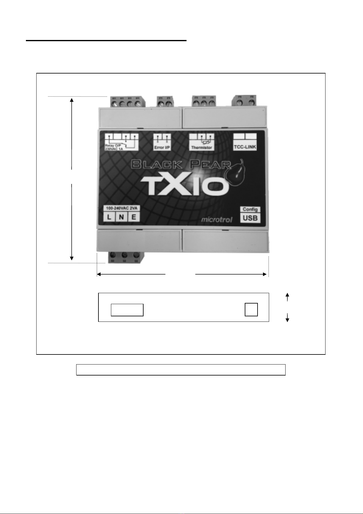
Fig. 1 Connection Details
Power
Supply
To HVAC
network
Error
Input
Relay
Output
To PC
for firmware
upgrading.
Thermistor
Input

4
3.1 Power Supply
The TXIO requires a 100-240v AC supply and has a consumption not exceeding 2VA. The
internal fuse is rated T630mA.
THIS EQUIPMENT MUST BE EARTHED
3.2 HVAC Communications Network ( TCC-LINK )
Can be connected to either U1/U2 or U3/U4 networks.
These are non-polarized.
Do not connect to the remote controller network.
3.3 Relay Output
The relay output is rated at 230V 1A. Normally-open and normally-closed terminals are
provided.
3.4 Error Input
This input accepts a volt-free contact. The polarity of the ‘active’ state is selectable via a
shorting link. See section 4.2.
3.5 Thermistor Input
Connecting a 10K301 thermistor to this input allows a temperature to be monitored by the
central controller or BMS interface.

5
4. Configuration
4.1 S1 Bitswitch Function
S1-1 On = 100 ohm terminator connected across the TCC-Link lines
Off = No terminating resistor.
Note:- Only one terminating resistor should be enabled per network
S1-2 On = Auto Restart (retain the I/O state as it was at power down)
Off = Start in the OFF condition
Fig. 2 LEDs and Config Switches
S1
Bitswitc
h
S2
Link
6
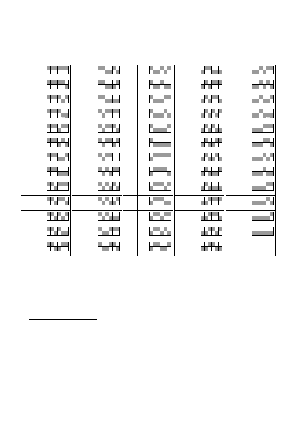
S1-3 to S1-8 Set the address of the unit; S1-3 = MSB : S1-8 = LSB
The address is the binary value of S1-3 to S1-8 plus 1.
(all switches off = 1, all switches on = 64)
1ON
OFF
345678 14 ON
OFF
345678 27 ON
OFF
345678 40 ON
OFF
345678 53 ON
OFF
345678
2ON
OFF
345678 15 ON
OFF
345678 28 ON
OFF
345678 41 ON
OFF
345678 54 ON
OFF
345678
3ON
OFF
345678 16 ON
OFF
345678 29 ON
OFF
345678 42 ON
OFF
345678 55 ON
OFF
345678
4ON
OFF
345678 17 ON
OFF
345678 30 ON
OFF
345678 43 ON
OFF
345678 56 ON
OFF
345678
5ON
OFF
345678 18 ON
OFF
345678 31 ON
OFF
345678 44 ON
OFF
345678 57 ON
OFF
345678
6ON
OFF
345678 19 ON
OFF
345678 32 ON
OFF
345678 45 ON
OFF
345678 58 ON
OFF
345678
7ON
OFF
345678 20 ON
OFF
345678 33 ON
OFF
345678 46 ON
OFF
345678 59 ON
OFF
345678
8ON
OFF
345678 21 ON
OFF
345678 34 ON
OFF
345678 47 ON
OFF
345678 60 ON
OFF
345678
9ON
OFF
345678 22 ON
OFF
345678 35 ON
OFF
345678 48 ON
OFF
345678 61 ON
OFF
345678
10 ON
OFF
345678 23 ON
OFF
345678 36 ON
OFF
345678 49 ON
OFF
345678 62 ON
OFF
345678
11 ON
OFF
345678 24 ON
OFF
345678 37 ON
OFF
345678 50 ON
OFF
345678 63 ON
OFF
345678
12 ON
OFF
345678 25 ON
OFF
345678 38 ON
OFF
345678 51 ON
OFF
345678 64 ON
OFF
345678
13 ON
OFF
345678 26 ON
OFF
345678 39 ON
OFF
345678 52 ON
OFF
345678
The address set by S1-3 to S1-8 is used for both the central TCC-Link address and also
for the Unit address in the Line/Unit addressing mode.
The Line address for the TXIO interface is always 29.
4.2 S2 Link Function
S2 controls the polarity of the ‘Error’ input signal.
Normally open signal (Closed=Error) Link S2-1 to S2-2 (bottom pair of pins)
Normally closed signal (Open = Error) Link S2-2 to S2-3 (top pair of pins)

7
4.3 LED Functions
LED 3 (Blue) Power (Flashing = ‘In Error’)
LED 2 (Red) TCC-Link Comms Flashes for each message
LED 1 (Amber) Output State (On = Active)
8
Appendix A : Physical Dimensions
.
Power
Supply
USB
107mm
33mm
110mm
Fig. 3 Dimensions

9
Appendix B : Document Revision History
Date Document Ver Firmware Ver By Comments
01/07/2017 v1.00 v1.10 mcb First version converted from
preliminary instructions.
05/07/2017 v1.01 v1.10 mcb Converted to booklet

Microtrol Ltd
16 Elgar Business Centre
Moseley Road
Hallow
Worcester
WR2 6NJ
UK
Tel: +44 (0)1905 641910
Email: sales@microtrol.co.uk
Table of contents
Other Microtrol Recording Equipment manuals


