Midea UR-BD199-DQ User manual

Service Manual_2018-V1.0
1
Service Manual
CHEST FREEZER SERIES
(The picture in this service manual is only for reference, and specific appearance and configuration are
subject to the real product)
Applicable Models
Model Code
UR-BD199-DQ
22032010003263
Prepared by
R&D: Huang Yanmin
Reviewed by
QA:WuXinbin
SVC:Zhang Kun
Approved by
R&D:ZhangHuawei
SVC:GuangTaoshuai

Service Manual_2018-V1.0
2
WARNING
Important Safety Notice
There are special components used in this equipment which are important for safety. These parts are marked
by in the Schematic Diagrams, Circuit Board Diagrams, Exploded Views and Replacement Parts List. It is
essential that these critical parts should be replaced with manufacturer’s specified parts to prevent shock, fire
or other hazards. Do not modify the original design without permission of manufacturer.
WARNING
Important Safety Notice
The Maintenance Manual is only for the use of maintenance personnel with certain experience and
background in electrical, electronic and mechanical field.
Any attempt to repair main devices may lead to personal injury and property loss.
Manufacturers or distributors are not responsible for the content of the Manual and interpretation thereof.
Midea Refrigerators
Technical Maintenance Manual
Copyright @2017
All rights reserved. Replication of all or part of the Manual in any forms shall not be allowed without written
approval by the Overseas Sales Corporation of Midea Refrigerators.

Service Manual_2018-V1.0
3
Contents
1. Safety Warning Code........................................................................................................................................... 5
1.1 Warning for operation safety..................................................................................................................... 5
1.2 Safety instruction for refrigerant............................................................................................................... 7
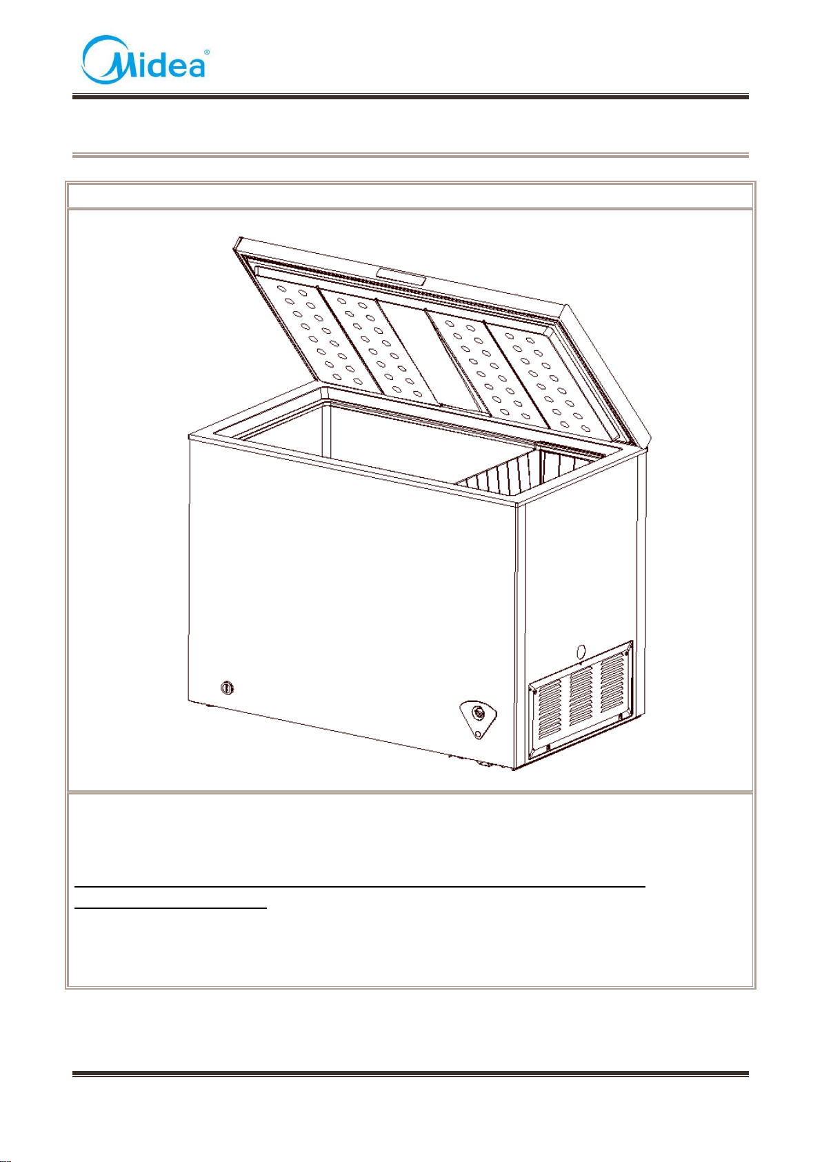
2. Description for product features......................................................................................................................... 8
3. Installation and commissioning .......................................................................................................................... 9
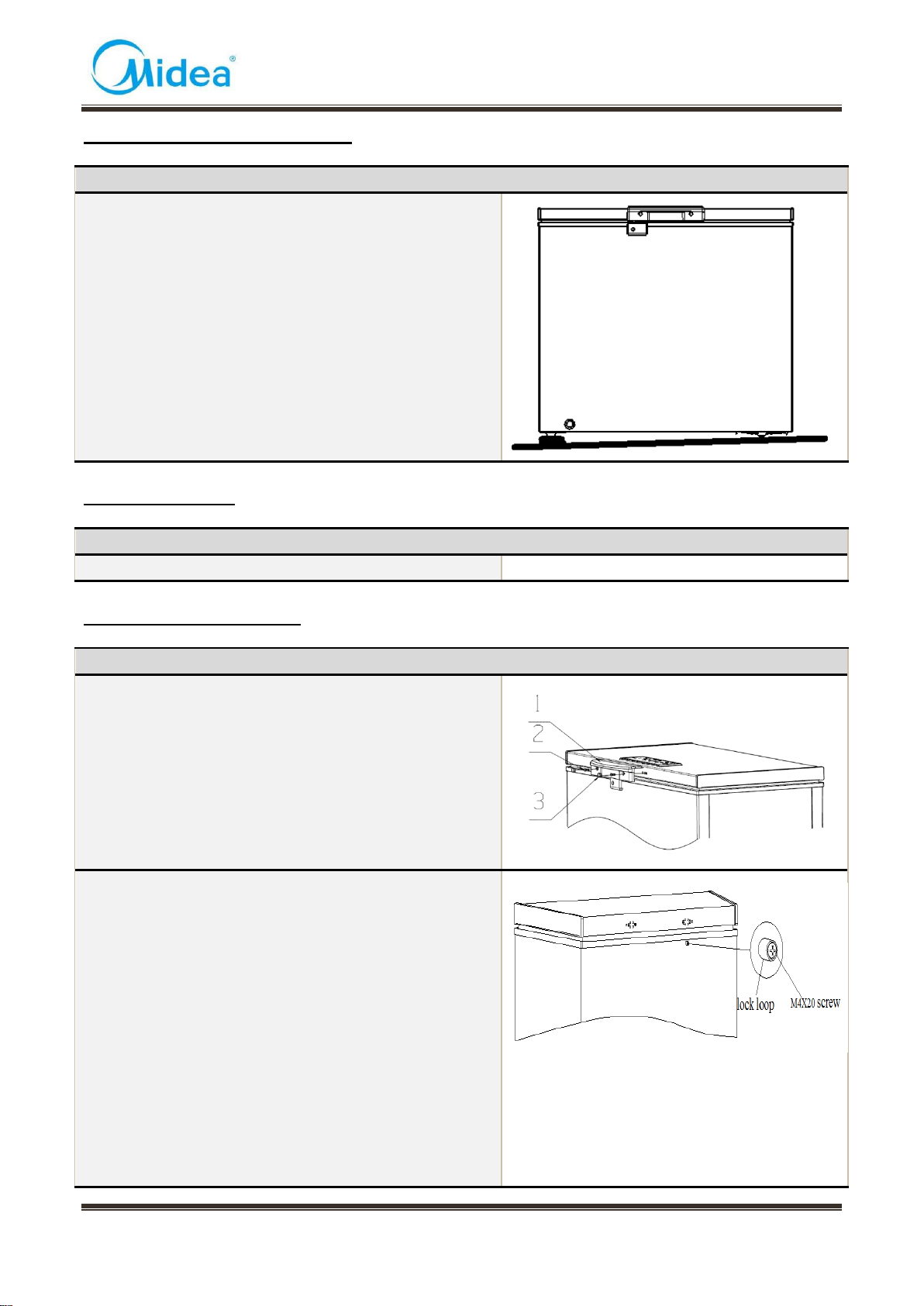
3.1 Handling....................................................................................................................................................... 9
3.2 Door Disassembly and Assembly............................................................................................................ 9
3.3 Installation location..................................................................................................................................... 9
3.4 Leveling of the refrigerator...................................................................................................................... 10
3.5 Door reversal............................................................................................................................................. 10
3.6 Installation of handle................................................................................................................................ 10
3.7 Installation of door lock............................................................................................................................ 11
3.8 Adjustment to level the door................................................................................................................... 11
3.9 Adjustment to shelves.............................................................................................................................. 11
4. Terms.................................................................................................................................................................... 12
4.1 Definition of model (None)...................................................................................................................... 12
4.2 Location of nameplate (None)................................................................................................................ 12
5. Product specification.......................................................................................................................................... 13
5.1 Type specification (None)........................................................................................................................ 13
5.2 Electrical parameters............................................................................................................................... 13
5.3 Inside temperature................................................................................................................................... 13
5.4 Defrosting parts........................................................................................................................................ 14
5.5 Circuit diagram.......................................................................................................................................... 14
6. Internal view and dimension............................................................................................................................. 15
6.1 Main parts and their names.................................................................................................................... 15
6.2 External dimension................................................................................................................................... 16
7. Refrigerating piping system and circulating route of cooling air.................................................................. 17
7.1 Refrigerating piping system.................................................................................................................... 17
7.2 Circulating route of cooling air................................................................................................................ 17
8. Dismantling of parts ........................................................................................................................................... 18
8.1 Parts on the door...................................................................................................................................... 18
8.2 Parts inside the refrigerator..................................................................................................................... 19
8.3 Light system.............................................................................................................................................. 20
8.4 Evaporator and temperature sensing system...................................................................................... 20
8.5 Condenser system ................................................................................................................................ 20
8.6 Compressor case..................................................................................................................................... 20
8.7 Temperature-control box assembly view .............................................................................................. 24
9. Function and operation...................................................................................................................................... 27
9.1 Operation panel........................................................................................................................................ 27
9.2 Temperature control................................................................................................................................. 27
9.3 give an alarm............................................................................................................................................. 27
9.4 Defrosting.................................................................................................................................................. 27

Service Manual_2018-V1.0
4
10. Circuit description............................................................................................................................................. 29
10.1 Power Supply(None).............................................................................................................................. 29
10.2 Test circuit for door switch(None) ........................................................................................................ 29
10.3 Temperature test circuit(None)............................................................................................................. 29
10.4 Freezer chamber fan motor circuit (None)......................................................................................... 29
10.5 refrigerating chamber fan motor circuit (None).................................................................................. 29
10.6 Condensation fan circuit (None).......................................................................................................... 29
10.7 Fan motor circuit of the ventilation door(None)................................................................................. 29
10.8 Resistance value of the sensor (R/T) (None) .................................................................................... 29
11. Troubleshooting Method.................................................................................................................................. 30
11.1 Not cooling............................................................................................................................................... 30
11.2 Not working of compressor................................................................................................................... 31
11.3 Thermostat malfunction-Undercooling................................................................................................ 31
11.4 Light is not on.......................................................................................................................................... 32
11.5 Noise........................................................................................................................................................ 32
12. Figures and details of repair parts(Documents are provided separately)................................................ 33
12.1 Figures..................................................................................................................................................... 33
12.2 List of parts and components............................................................................................................... 33
13. Appendix............................................................................................................................................................ 34
13.1 Refrigerator maintenance tooling and equipment and material...................................................... 34

Service Manual_2018-V1.0
5
1. Safety Warning Code
1.1 Warning for operation safety
Important Safety Instructions
CAUTION
RISK OF ELECTRIC SHOCK
DO NOT OPEN
This symbol indicates that dangerous voltage
constituting a risk of electric shock is present
within your freezer.
This symbol indicates that there are important
operating and maintenance instructions in the
literature accompanying your freezer.
WARNING
1) Read these instructions.
2) Keep these instructions.
3) Heed all warnings.
4) Follow all instructions.
5) Do not use this appliance near water.
6) Clean only with a damp cloth.
7) Do not block any ventilation openings.
8) Install in accordance with the manufacturer’s instructions.
9) Do not install near any heat sources, such as radiators, heat registers, stoves, or
other apparatus that produce heat.
10) Do not defeat the safety purpose of the polarized or grounding-type plug.A
polarized plug has two blades with one wider than the other. A grounding type plug has two
blades and a third grounding prong. The wide blade or the third prong are provided for your
safety. If the provided plug does not fit into your outlet, consult an electrician for replacement
of the obsolete outlet.
11) Protect the power cord from being walked on or pinched, particularly at plugs,
convenience receptacles, and the point where they exit from the appliance.
12) Do not attempt to modify or extend the power cord of this appliance.
13) Unplug this appliance during lightning storms or when it will not be used for long
periods of time.
14) Make sure that the available AC power matches the voltage requirements of this
appliance.

Service Manual_2018-V1.0
6
CONNECTING ELECTRICITY
Electrical Shock Hazard.
Plug into a grounded 3-prong outlet.
Do not remove the ground prong.
Do not use an adapter.
Failure to follow these instructions can
result in death, fire, or electrical shock.
WARNING
Electric Shock Hazard
Failure to follow these instructions can result in electric shock, fire, or
death.
1) WARNING–Keep ventilation openings, in both the freezer and the built-in structure,
clear of obstruction.
2) WARNING–Do not touch the interior of the freezer with wet hands. This could result
in frost bite.
3) WARNING–Do not use mechanical devices or other means to accelerate the
defrosting process, other than those recommended by the manufacturer.
4) WARNING–Do not damage the refrigerant circuit.
5) WARNING–Do not damage the refrigerant tubing when handling, moving, or using
the freezer.
6) WARNING–DANGER–Never allow children to play with, operate, or crawl inside the
freezer. Risk of child entrapment. Before you throw away your old freezer:
6-1) Take off the doors
6-2) Leave the shelves in place so that children may not easily climb inside
7) Unplug the freezer before carrying out user maintenance on it.
8) This freezer can be used by children age eight years and older and persons with
reduced physical or mental capabilities or lack of experience and knowledge if they are
given supervision or instruction concerning the use of the freezer in a safe way and
understand the hazards involved. Children should not play with the freezer. Cleaning and
maintenance should not be performed by children without supervision.
9) If a component part is damaged, it must be replaced by the manufacturer, its service
agent, or similar qualified persons in order to avoid a hazard.
10) Please dispose of the freezer according to local regulations as the freezer contains
flammable gas and refrigerant.
11) Follow local regulations regarding disposal of the freezer due to flammable
refrigerant and gas. All refrigeration products contain refrigerants, which under the
guidelines of federal law must be removed before disposal. It is the consumer's
responsibility to comply with federal and local regulations when disposing of this product.
12) This freezer is intended to be used in household and similar environments.

Service Manual_2018-V1.0
7
13) Do not store or use gasoline or any flammable liquids inside or in the vicinity of this
freezer.
14) Do not use extension cords or ungrounded (two-prong) adapters with this freezer. If
the power cord is too short, have a qualified electrician install an outlet near the freezer. Use
of an extension cord can negatively affect the freezer’s performance.
Grounding requirement
This freezer must be grounded. This freezer is equipped with a cord having a grounding
wire with a grounding plug. The plug must be inserted into an outlet that is properly installed
and grounded.
Improper use of the grounding plug can result in a risk of electric shock. Consult a
qualified electrician or service person if the grounding instructions are not completely
understood, or if doubt exists as to whether the freezer is properly grounded.
1.2 Safety instruction for refrigerant
Explosion Hazard.
Keep flammable materials and vapors, such as gasoline, away from freezer. Failure to do so
can result in fire, explosion, or death.
Safety instruction for refrigerant
DANGER–Risk of Fire or Explosion. Flammable Refrigerant Used. To Be Repaired Only By
Trained Service Personnel. Do Not Use Mechanical Devices. Do Not Puncture Refrigerant
Tubing. CAUTION–Risk of Fire or Explosion. Flammable Refrigerant Used. Consult Repair
Manual/Owner’s Guide Before Attempting To Service This Product. All Safety Precautions
Must be Followed. CAUTION–Risk of Fire or Explosion. Dispose of Properly InAccordance
With Federal Or Local Regulations. Flammable Refrigerant Used. CAUTION–Risk of Fire or
Explosion Due To Puncture Of Refrigerant Tubing; Follow Handling Instructions Carefully.
Flammable Refrigerant Used.

Service Manual_2018-V1.0
8
2. Description for product features
This product is provided with following features:
1) Fan-shaped temperature control panel with kitchen cabinet of complete freezing type
2) top single opening design

Service Manual_2018-V1.0
9
3. Installation and commissioning
3.1 Handling
Handling
1)Protect the refrigerator in moving it,Same as shown as
left photo, please move it by handcart with cushion
2)Remove all packing materials and bottom cushion, the
n move into house for placement
3)After moving it to appropriate location, wait for 2 hours
before power on.
3.2 Door Disassembly and Assembly
The refrigerator door needs to be dismantled if it cannot enter the room in the whole.
Disassembly of Freezer door
None
Disassembly of refrigerator door
None
3.3 Installation location
Installation location
Location that is easy for ventilation shall be chosen to
facilitate heat dissipation, enhance its performance and
reduce the energy consumption.

Service Manual_2018-V1.0
10
3.4 Leveling of the refrigerator
Leveling of the refrigerator
If the refrigerator cannot be placed steadily, adjust the
footing to level it.
3.5 Door reversal
Door reversal
Door reversal
None
3.6 Installation of handle
Installation of handle
1- Handle
2- M5*14 screw(two)
3- Screw hole cover (two)
1) The handle is inserted below the display control board
of door, aligning with the screw hole.
2) Fixing the handle by using the screw.
3) Assemble the screw hole cover onto the screw hole.
1.Fix the lock loop to its mounting hole near the frame in
the front side plate of the box with a M4x20 or M4x8
screw. Pay attention to the direction of the lock loop with
its countersunk side facing outwards.
2.Hold the handle with the left hand, and aim its
mounting hole at the mounting hole of the door. Insert the
key into the keyhole with the right hand, and then turn the
key clockwise to drive the rotation of the lock hook.
Meanwhile, adjust the position of the handle from side to
side in a proper manner to ensure the lock hook can
hook the lock loop in locked state. Afterwards, fix the
handle to the door with four M5X16 screws.
3.Install the handle cover

Service Manual_2018-V1.0
11
3.7 Installation of door lock
Installation of door lock
With the door handle together
3.8 Adjustment to level the door
Adjustment to level the door
None
3.9 Adjustment to shelves
Adjustment to shelves
None

Service Manual_2018-V1.0
12
4. Terms
4.1 Definition of model (None)
4.2 Location of nameplate (None)

Service Manual_2018-V1.0
13
5. Product specification
5.1 Type specification (None)
5.2 Electrical parameters
Product Name
UR-BD199-DQ
None
Product Code
22032010003263
None
Item
Specification
Specification
Compressor
Compressor
FZ59E1G
None
Starter(PTC)
QP2-4R7
None
Overload protector(OLP)
DRB29T61A1
None
Winding resistance of compressor wiring
terminal
Rmc:7.02-8.08Ω
Rsc:8.88-10.22Ω
Rms=Rmc+Rsc
None
Winding resistance picture
None
Variable frequency driver board
None
None
Motor
Fan motor of the freezing chamber
None
None
Ventilation door of the refrigerating
chamber
None
None
Condensation fan
None
None
separation the ice motor
None
None
ice output motor
None
None
Open door motor
None
None
Lights
Lights inside the freezing chamber
None
None
Lights inside the refrigerating chamber
None
None
Switch of the refrigerator door
None
None
Indicator lamp
None
None
5.3 Inside temperature
Temperature tolerance ≤ 2 oC
Compartment
The highest (oC)
Lowest (oC)
Freezing
-12
-28
Refrigerating
None
None
Variable temperature
None
None

Service Manual_2018-V1.0
14
5.4 Defrosting parts
Item
Initial defrosting period
Normal defrosting period
Defrosting period
None
None
Defrosting sensor
None
None
Defrosting temperature
controller
None
None
Thermal fuse
None
None
Defrosting heater in freezing
chamber
None
None
5.5 Circuit diagram

Service Manual_2018-V1.0
15
6. Internal view and dimension
6.1 Main parts and their names
Freezer chamber
Freezer chamber
❶Door shell
❷The door end cover
❸Door gasket
❹Door liner
❺Cabinet assembly
❻Drain-pipe cover
❼Levelling feet
❽Compressor mounting panel
❾Temperature-control panel
❿Hinge
⓫Lamp cover
⓬Door handle

Service Manual_2018-V1.0
16
6.2 External dimension
Description
Code
Size (mm)
Size (mm)
Height to Top of Case
A
845
None
Width
B
818
None
Depth/Hinge
C
555
None
Depth
D
540
None
Height (Door open)
E
1330
None

Service Manual_2018-V1.0
17
7. Refrigerating piping system and circulating route of cooling air
7.1 Refrigerating piping system
UR-BD100-DQ_22032010003261
❶Compressor→❷Right condenser→❸Left Condenser→❹Dry filter→❺Capillary tube→❻Evaporator
7.2 Circulating route of cooling air

Service Manual_2018-V1.0
18
8. Dismantling of parts
8.1 Parts on the door
Door seal
1)Pull the door seal from the corner
2)Take efforts until door seal totally detaches from door
inner liner groove, remove the door seal
3)Fixing the four corners and pressing smoothly.
The hinge cover
1) Open the upper hinge of the lower hinge cover by
hand to a certain angle until the hinge cover is separated
from the certain distance.
2) Pull down the lower hinge cover.

Service Manual_2018-V1.0
19
3) Open the slanted upward of hinge cover to a certain
angle by a screwdriver and remove the hinge cover.
Wear safety gloves for fear of cutting the hand.
1) When the door is closed, open the lower hinge cover
along the side wall to a suitable angle and push forwards
into the side wall of the hinge until the hinge cover boss
completely falls into the hinge hole.
2) Hold the side of upper hinge cover with both
hands, align the opening with the side wall of the hinge,
and push down until the hinge cover protrusion
completely falls into the hinge hole. Then the upper and
lower hinge covers are all in place.
Door light disassembly and assembly
None
8.2 Parts inside the refrigerator
Basket
Open the door and removed the basket
Inside water pipe cover

Service Manual_2018-V1.0
20
Counterclockwise to remove the pipe cover
Ice tray
Ice tray
None
8.3 Light system
Light
Light
None
Light switch
Light switch
None
Indicator lamp
Indicator lamp
None
8.4 Evaporator and temperature sensing system
Freezer sensor
Freezer sensor
None
Ambient temperature sensor
None
Thermostat
Electronic control/Machine
machine
8.5 Condenser system
Condenser
Condenser
Inside
8.6 Compressor case
shutter and compressor case
This manual suits for next models
1
Table of contents
Other Midea Freezer manuals

Midea
Midea MD-RT468WEDMX02 User manual

Midea
Midea FF172L User manual

Midea
Midea HS-185CN User manual

Midea
Midea MF411W User manual

Midea
Midea MDRC152FZG01-SG User manual

Midea
Midea MRU17F6AWW User manual

Midea
Midea UR-BD481WE1-DT User manual

Midea
Midea JHSD172 User manual

Midea
Midea MCH198W User manual

Midea
Midea MCH142W User manual

Midea
Midea WF130 User manual

Midea
Midea COMPACT Series User manual

Midea
Midea UR-BD295-DQ User manual

Midea
Midea SINGLE DOOR Series User manual

Midea
Midea MRC04M3AWW User manual

Midea
Midea HS-338FWEN-W User manual

Midea
Midea MF172W User manual

Midea
Midea MU138SWAR1RC1 User manual

Midea
Midea HS-186CN User manual

Midea
Midea UR-BD100-DQ User manual