1. Read Instructions - All the safety and operating
instruction should beread before theproduct is
operated.
2. Retain Instructions - The safety and operating
instruction should be retained for future
reference.
3. Heed Warnings - All warning on the product and
in the operating instructions should be adhered to.
4. Follow instructions - All operating and use
instructions should be followed.
5. Cleaning -Unplug this productfrom the wall
outlet before cleaning. Do not use liquid cleaners
or aerosol cleaners. Use a damp cloth for cleaning.
6. Attachments - Do not use attachments not
recommended by theproduct manufacturer as
they may cause hazards.
7. Water and Moisture- Do notuse this productnear
water - forexample, near abath tub, washbowl,
kitchen sink, or laundry tub; in a wet basement, or
near a swimmingpool, and thelike.
8. Accessories -Do not placethis product onan
unstable cart, stand tripod, bracket, or table. The
product may fall,causing serious injuryto a child
or adult, andserious damage tothe product. Use
only with acart, stand, tripod,bracket, or table
recommended by themanufacturer, orsold with
the product. Anymounting of theproduct should
follow the manufacturer s instructions, and
should use amounting accessory recommended
by the manufacturer.
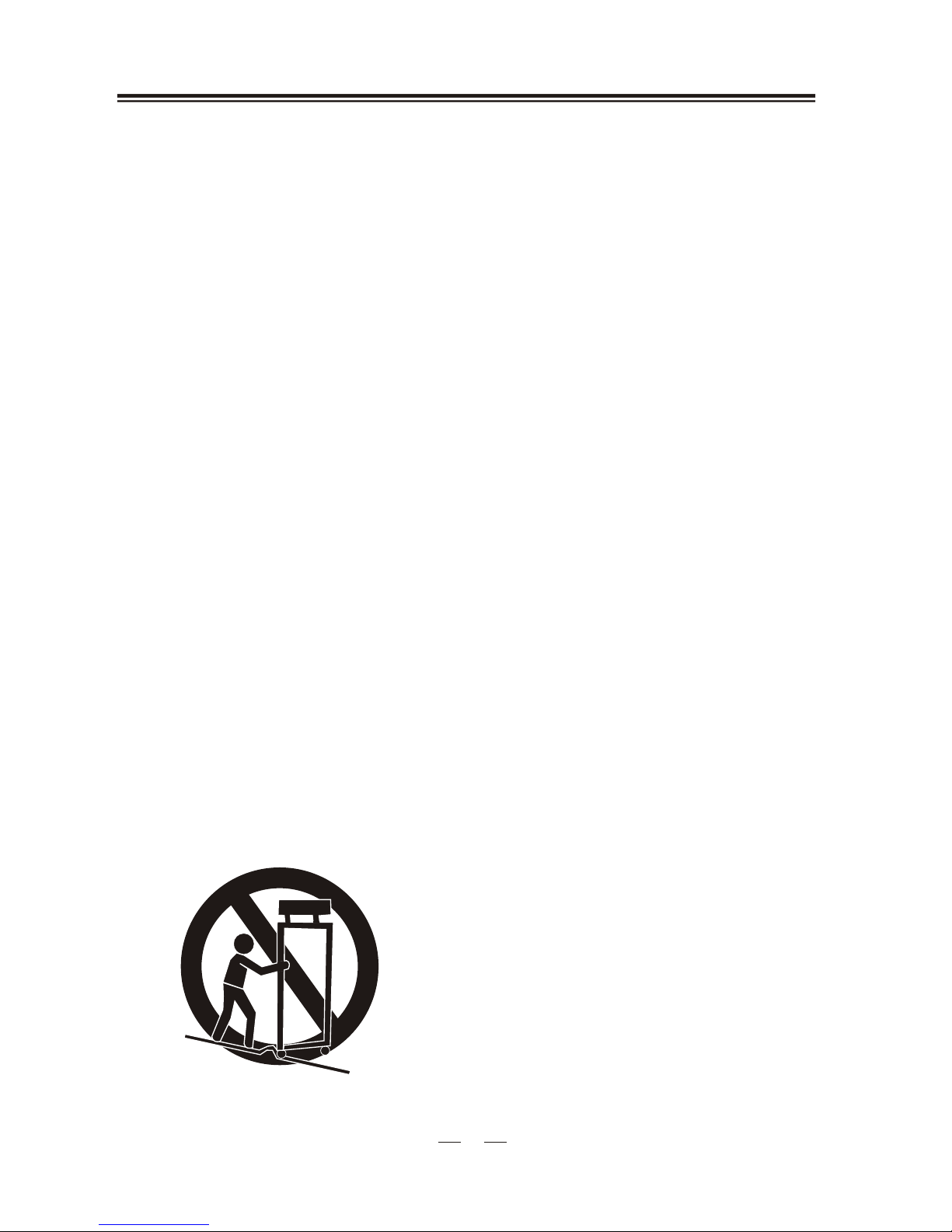
9. A productand cart combinationshould be moved
with care. Quick stops, excessive force, and
uneven surfaces may cause the appliance and cart
combination to overturn.
33
10. Ventilation - Slots and openings in the cabinet are
provided for ventilationand to ensurereliable
operation of the product and to protect it from
overheating, and these openings must not be
blocked or covered. The openings shouldnever
be blocked byplacing the producton a bed,sofa,
rug, or othersimilar surface. Thisproduct should
not be placedin a built- in installationsuch as a
bookcase or rackunless proper ventilationis
provided or the manufacturer s instruction have
been adhered to.
11. PowerSources - Thisproduct should be operated
only from the type of power source indicated on
the marking label. If you are not sure of the type
of power supply to your home, consult your
product dealer or local power company. For
products intended tooperate from batterypower,
or other sources, refer to the operating
instruction.
12. Grounding or Polarization - This product may be
equipped with a polarized alternating current line
plug (a plug having one blade wider than the
other). This plugwill fit intothe power outlet
only one way. This is a safety feature. If you are
unable to insert the plug fully into the outlet, try
reversing the plug,If the plugshould still failto
fit, contact your electrician to replace your
obsolete outlet. Do not defeat the safety purpose
of the polarizes plug.
13. Alternate Warnings - Thisproduct is equipped
with a three- wire grounding - type plug, a plug
having a third(grounding) pin. Thisplug will
only fit intoa grounding -type power outlet. This
is a safety feature. If you are unable to insert the
plug into theoutlet, contact yourelectrician to
replace your obsolete outlet. Do not defeat the
safety purpose of the grounding - type plug.
Power - Cord protection - Power supply cords
should be routed so that they are not likely to be
walked on or pinched by items placed upon or
against them, paying particular attention to cords
at plugs, convenience receptacles, and point
where they exitfrom the product.
14. Protective AttachmentPlug - Theproduct is
equipped with an attachment plug having
overload protection. Thisis a safetyfeature. See
Instruction Manual for replacement or resetting
of protective device. If replacement ofthe plug is
required, be surethe service technicianhas used
a replacement plugspecified by themanufacturer
that has the same overload protection as the
original plug.
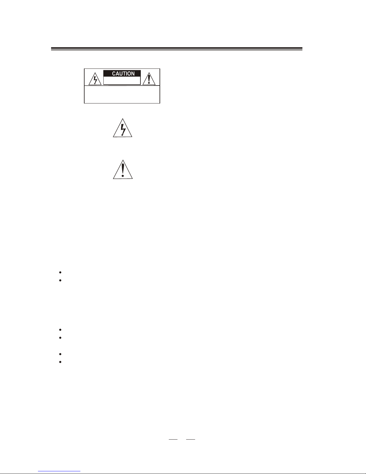
IMPORTANT SAFEGUARDSIMPORTANT SAFEGUARDS
,