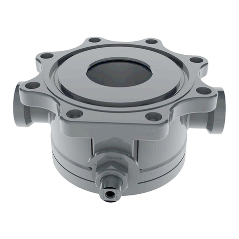
Midland A-7200 Instruction manual

P/N: A-7200/A-7300, Ver. 1.0
Issue Date: April 27, 2020
Top-Transfer Ball Valve
A-7200/A-7240 and A-7300/A-7340
Installation, Operation & Maintenance (IOM) Manual

A-7200/A-7300, Ver. 1.0
Page 2 of 21
Table of Contents
Regulations and Safety Requirements...........................................................................................3
Regulations............................................................................................................................3
Safety Warnings and Precautions...........................................................................................3
Introduction.................................................................................................................................... 4
Component Identification and Parts Listings...........................................................................4
Torque and Bolt Size Table References.................................................................................7
Valve Installation............................................................................................................................ 8
Installation and Required Tools.............................................................................................. 8
Leak Inspection......................................................................................................................8
Valve Operation Notes and Precautions................................................................................. 9
Valve Qualification ....................................................................................................................... 10
Valve Disassembly and Required Tools ............................................................................... 10
Component Inspection.......................................................................................................... 13
Valve Assembly and Testing Requirements ......................................................................... 15
Valve Assembly and Testing Procedure............................................................................... 16
Routine Maintenance................................................................................................................... 20
Leak Checking in the Field................................................................................................... 20

A-7200/A-7300, Ver. 1.0
Page 3 of 21
1Regulations and Safety Requirements
Regulations
Midland Top-Transfer Ball Valves are used in contact with a variety of products, many of which are hazardous materials.
The acceptance and transportation of products are regulated by the DOT and AAR in the U.S.A., and in Canada by CTC
and Transport Canada. Regulations of other governmental bodies must be complied with for stationary and mobile
applications. All personnel should be familiar with and follow these regulations. Nothing in these instructions is intended
to conflict with or supersede these regulations. The information in this document was gathered from knowledgeable
sources. However, Midland Manufacturing Corporation makes no representations or guarantees about its accuracy or
completeness and assumes no liability for this information.
Specifications are subject to change without notice.
Midland valves are used in connection with a variety of products, many of which are hazardous materials and could cause
serious injury or damage if mishandled. This valve should only be installed, operated and maintained by qualified
personnel. Read all of these instructions carefully before proceeding.
Operation of the valve must conform to all applicable specifications from TC, AAR, DOT, CFR (Parts 173.31, 174.67, etc.)
and other governmental bodies, along with the operating instructions of your company.
Safety Warnings and Precautions
Please carefully read each of the following warnings and cautions prior to performing any work.
WARNING: Toxic Hazard. Always use extreme caution and proper equipment when involved with
hazardous materials. To avoid exposure to toxic or hazardous materials, make sure the tank car is empty
and clean, and that the work area is free of hazardous chemicals before removing or installing any valve.
•Wear protective clothing and equipment suitable for withstanding the materials to which
you may be exposed
•Position yourself on the upwind side of the valve when possible
•Work in a well-ventilated area
•Work with a partner who can help you in the event of an emergency
•Follow approved safety precautions for hazardous or toxic materials
•Obtain MSDS sheets for all the commodities used with the associated valve
CAUTION: Valve Leakage. Loose nuts and damaged gaskets may result in leaks at the valve-mounting
joint.
CAUTION: Sealing Surface Damage. A damaged sealing surface on the valve flange may prevent proper
sealing on the tank-car mounting and result in leakage of the tank contents.

A-7200/A-7300, Ver. 1.0
Page 4 of 21
2Introduction
The A-7200 and A-7240 Series -Transfer Ball Valve and A-7300 and A--Transfer Ball Valve
offer greater resistance to abrasion. The valve also reduces the chance of leakage caused by particle contamination in
harsh applications.
•Available in carbon steel -or stainless steel -
Component Identification and Parts Listings
A-7200 and A-7240 Bill of Materials

A-7200/A-7300, Ver. 1.0
Page 5 of 21
A-7300 and A-7340 Bill of Materials
ITEM DESCRIPTION QTY MATERIAL PART NUMBER MATERIAL PART NUMBER
1 END CAP 1
CARBON STEEL 7200-1-CS 316 STAINLESS STEEL 7240-1-MO
2 STEM 1 STAINLESS STEEL 7200-2-SS STAINLESS STEEL 7200-2-SS
3 BALL 1 316 STAINLESS STEEL 7200-3-SS 316 STAINLESS STEEL 7240-3-MO
4 BODY 1 CARBON STEEL 7200-4-CS 316 STAINLESS STEEL 7240-4-MO
5 PACKING SEAL 1 PTFE 7200-5-TF PTFE 7200-5-TF
6 SPACER 1 304 STAINLESS STEEL 7200-6-SS 304 STAINLESS STEEL 7200-6-SS
7
SOCKET HEAD CAP SCREW
1 304 STAINLESS STEEL 7240-7-SS 304 STAINLESS STEEL 7240-7-SS
8NUT 1 304 STAINLESS STEEL 7240-8-SS 304 STAINLESS STEEL 7240-8-SS
9 HEXCAP SCREW 4 304 STAINLESS STEEL 7240-9-SS 304 STAINLESS STEEL 7240-9-SS
10 LOCKWASHER 4 304 STAINLESS STEEL 7240-10-SS 304 STAINLESS STEEL 7240-10-SS
11 SEAL, BALL 2 SEE TABLE SEE TABLE SEE TABLE SEE TABLE
12 LOCKWASHER 1 304 STAINLESS STEEL 7200-12-SS 304 STAINLESS STEEL 7200-12-SS
13 GROUNDING SPRING 1 301 STAINLESS STEEL 7200-13-SS 301 STAINLESS STEEL 7200-13-SS
14 GASKET 1 PTFE 7200-14-TF PTFE 7200-14-TF
15 NUT LOCK 1 304 STAINLESS STEEL 7200-15-SS 304 STAINLESS STEEL 7200-15-SS
16 DISC SPRING 2 301 STAINLESS STEEL 7200-16-SS 301 STAINLESS STEEL 7200-16-SS
17 PACKING NUT 2 304 STAINLESS STEEL 7200-17-SS 304 STAINLESS STEEL 7200-17-SS
18 HANDLE W/COVER,RH 1 ALLOYSTEEL 7200-18-AS ALLOY STEEL 7200-18-AS
19 THRUST WASHER 1 PTFE 7200-19-TF PTFE 7200-19-TF
20 PACKING PROTECTOR 1 PTFE 7200-21-TF PTFE 7200-21-TF
21 DRIVE SCREW 2 STAINLESS STEEL 763-11-SS STAINLESS STEEL 763-11-SS
22 NAME PLATE 1 STAINLESS STELL 7200-22-SS STAINLESS STEEL 7240-22-SS
23 WASHER 1 STAINLESS STEEL 7200-20-SS STAINLESS STEEL 7200-20-SS
A-7240 (STAINLESS STEEL)
A-7200 (CARBON STEEL W/ STAINLESS STEEL TRIM)
VALVE PART NO. ITEM 11, SEAL MATERIAL
A-7200 7200-11-VTF VIRGINPTFE
A-7240 7200-11-VTF VIRGINPTFE

A-7200/A-7300, Ver. 1.0
Page 6 of 21
ITEM DESCRIPTION QTY MATERIAL PART NUMBER MATERIAL PART NUMBER
1 END CAP 1
CARBON STEEL 7300-1-CS 316 STAINLESS STEEL 7340-1-MO
2 STEM 1 STAINLESS STEEL 7300-2-SS STAINLESS STEEL 7300-2-SS
3 BALL 1 316 STAINLESS STEEL 7300-3-SS 316 STAINLESS STEEL 7340-3-MO
4 BODY 1 CARBON STEEL 7300-4-CS 316 STAINLESS STEEL 7340-4-MO
5 PACKING 1 PTFE 7300-5-TF PTFE 7300-5-TF
6 SPACER 1 304 STAINLESS STEEL 7300-6-SS 304 STAINLESS STEEL 7300-6-SS
7
SOCKET HEAD CAP SCREW
1 304 STAINLESS STEEL 7340-7-SS 304 STAINLESS STEEL 7340-7-SS
8NUT 1 304 STAINLESS STEEL 7340-8-SS 304 STAINLESS STEEL 7340-8-SS
9 HEXCAP SCREW 6 304 STAINLESS STEEL 7340-9-SS 304 STAINLESS STEEL 7340-9-SS
10 LOCKWASHER 6 304 STAINLESS STEEL 7240-10-SS 304 STAINLESS STEEL 7240-10-SS
11 SEAL, BALL 2 SEE TABLE SEE TABLE SEE TABLE SEE TABLE
12 LOCKWASHER 1 304 STAINLESS STEEL 7300-12-SS 304 STAINLESS STEEL 7300-12-SS
13 GROUNDING SPRING 1 301 STAINLESS STEEL 7300-13-SS 301 STAINLESS STEEL 7300-13-SS
14 GASKET 1 PTFE 7300-14-TF PTFE 7300-14-TF
15 NUT LOCK 1 304 STAINLESS STEEL 7300-15-SS 304 STAINLESS STEEL 7300-15-SS
16 DISC SPRING 2 301 STAINLESS STEEL 7300-16-SS 301 STAINLESS STEEL 7300-16-SS
17 PACKING NUT 2 304 STAINLESS STEEL 7300-17-SS 304 STAINLESS STEEL 7300-17-SS
18 HANDLE W/COVER 1 ALLOYSTEEL 7300-181-AS ALLOYSTEEL 7300-181-AS
19 THRUST WASHER 1 PTFE 7300-19-TF PTFE 7300-19-TF
20 PACKING PROTECTOR 1 PTFE 7300-20-TF PTFE 7300-20-TF
21 SPACER 1 304 STAINLESS STEEL 7340-21-SS 304 STAINLESS STEEL 7340-21-SS
22 NAME PLATE 1 STAINLESS STEEL 7200-22-SS STAINLESS STEEL 7240-22-SS
23 DRIVE SCREW 2 STAINLESS STEEL 763-11-SS STAINLESS STEEL 763-11-SS
A-7340 (STAINLESS STEEL)
A-7300 (CARBON STEEL W/ STAINLESS STEEL TRIM)
VALVE PART NO. ITEM 11, SEAL MATERIAL
A-7300 7300-11-VTF VIRGINPTFE
A-7340 7300-11-VTF VIRGINPTFE

A-7200/A-7300, Ver. 1.0
Page 7 of 21
Torque and Bolt Size Table References
Refer to these tables when selecting the necessary tooling per the instructions in Section 3.4 and Section 4.0, as
well as following any guidelines for fastening torques.
NOTE: The “M” as displayed in Table 2-2’s “M 22” is referencing Metric.
Table 2-1
Valve Size
Bolt Size
Number of Bolts
- 11 UNC
4
- 11 UNC
4
Table 2-2
Valve Size
Packing Nut Size
Fastening Torques
-10 UNC
23 - 28 ft-lb
M 22
30 - 36 ft-lb
Table 2-3
Valve Size
Body Joint
Bolt Size
Number of Bolts
Fastening Torques
M 12
4 or 6
53 - 65 ft-lb
Table 2-4
Bolt Size
Wrench/Socket
Size
5/8"
1-1/16"
3/4"
1-1/8" or M 26
M 22
M 32
M 12
M 19

A-7200/A-7300, Ver. 1.0
Page 8 of 21
3Valve Installation
Keep the new Top-Transfer Ball Valve in its original shipping container. This will ensure that it remains clean and will
protect the gasket face and ball from nicks and other damage.
Prior to installation, ensure that the valve remains clean and the gasket-sealing surfaces are not damaged.
Installation and Required Tools
SAE Wrench
Component(s)/Description
1-
Other Tools Supplies and Equipment
Solvent
To clean the mounting and sealing surfaces
Clean Cloth
To clean sealing surfaces
Ensure the stud threads are clean.
Examine the sealing surface to verify that there are no dents or burrs.
Up to this point, the new valve should have been kept in its original shipping container and a special plastic
protector should have been positioned over the sealing surface on the bottom of the valve.
Remove plastic protector from bottom of the valve.
If the valve is reconditioned, or retested, inspect the sealing surface to ensure it is free of nicks, gouges and
burrs.
Properly install a new mounting gasket (not provided by Midland).
Start all four (4) hex nuts on the studs while lowering the valve into position or the valve will need to be lifted off
the studs and the hex nuts started to give clearance.
Gently lower the valve down onto the cover plate.
Wrench-tighten the nuts a little bit at a time, going alternately in a crisscross pattern, from 1 to 3, then 2 to 4. Do
not tighten down too much on one side because this will shift the valve at an angle and may make it impossible
to get a tight gasket seal.
Torque the nuts to a level prescribed by your engineering department. In absence of a recommended company
practice, on clean and lubricated threads it should be safe to torque the mounting nuts to 200 ft-lbs max.
Leak Inspection
Test all newly installed valves to verfiy that they conform to car-owner specifications. No leaks should be present.

A-7200/A-7300, Ver. 1.0
Page 9 of 21
Valve Operation Notes and Precautions
NOTICE: Valve Operation. Operation and use of the valve must conform with all applicable TC,
AAR and DOT (Parts 173.31, 174.68, etc.) regulations, other governmental bodies and the
operating instructions of your company.
Rotate bar handle to operate valve open (figure
on left) and close (figure on right).
To ensure the valve is fully open, or closed, fully
engage the handle to the pin stops.
Open Position
Closed Position

A-7200/A-7300, Ver. 1.0
Page 10 of 21
4Valve Qualification
Follow these instructions and guidelines for assessing the condition of a leaking ball valve prior to rebuilding it.
NOTICE: To ensure best practice and consistency of your qualification procedure, gaskets, O-
rings, valve seats and wire seals should always be replaced.
Valve Disassembly and Required Tools
SAE Wrench
Component(s)/Description
1-*
Or M26 Wrench*
Packing Nut (item 17)
M19 Wrench
Cap Screws (item 9)
Other Tools, Supplies and Equipment
Thread Go/No-Go Gauge
3/4-10UNC, M22
Stem (item 2)
* Refer to Table 2-4 to select the correct tooling
Set the valve to the closed position (Figure 4-1). This must be done to allow
removal of the valve ball.
Hold the valve securely by the flange for safety and rigidity during hardware
removal.
Figure 4-1
Remove the nut (item 17) from the stem (item 2) by turning it counterclockwise.
Then remove the handle (item 18) and lockwasher (item 12). (Figure 4-2)
Figure 4-2
17
18
12
2

A-7200/A-7300, Ver. 1.0
Page 11 of 21
Remove the four (4) socket hex-head cap screws (item 9) and lockwashers
(item 10) from the end cap (Item 1). (Figure 4-3)
Figure 4-3
Carefully lift off the end cap (item 1) taking care to avoid contacting it with the
valve ball (item 3). Remove gasket (item 14) from the body (item 4).
Remove the ball seal (Item 11) from the end cap (item 1). (Figure 4-4)
Figure 4-4
Reach both hands into the valve body (item 4) on either side of the valve ball
(item 3). Lift the ball out of the body and set it on a padded surface. (Figure 4-
5)
Figure 4-5
Remove the packing nut (Item 17) from the valve stem (item 2) by turning it
counterclockwise. (Figure 4-6)
Figure 4-6
17
2
1
14
11
4
3
10
9
1
4
3

A-7200/A-7300, Ver. 1.0
Page 12 of 21
Remove the disc springs (item 16) and spring (item 13). (Figure 4-7)
Figure 4-7
Carefully press the valve stem (item 2) into the body (item 4) cavity and remove
it. (Figure 4-8)
Figure 4-8
Remove the stainless-steel spacer collar (item 6), packing protector (item 20),
and packing seals (item 5) from the valve-stem bore. Avoid scratching or
gouging the interior surfaces for the valve-stem bore. (Figure 4-9)
Figure 4-9
Carefully remove the ball seal (item 11) from the inside-bottom of the valve body
(item 4). (Figure 4-10)
Figure 4-10
13
2
16
2
4
4
11
6
20
5

A-7200/A-7300, Ver. 1.0
Page 13 of 21
Component Inspection
NOTICE: Without consent from the valve manufacturer or car owner, repair work is limited to
cleaning and polishing. See AAR M 1002, Paragraph A3.11.1 of the Tank-Car Specifications.
NOTICE: Procedures may not cover all conditions encountered in the field. Therefore, it is the
responsibility of the repair agency to obtain approval from Midland for inspection, evaluation,
repair and maintenance procedures not covered herein. Evaluation of critical component metal
surfaces of the valves after cleaning, inspection and specialized testing performed by agencies
other than Midland are the responsibility of the repair facility. Where numerical tolerances can
be provided, the disposition of the internal integrity and surface quality of parts is under the
jurisdiction of the repair facility and dependent on its experience and judgment.
Valve-Body Inspection
4.2.1.1 Check the valve body (item 4) and the ball-seal
surfaces for signs of corrosion, cracks and
scratches. No defects are allowed.
4.2.1.2 Inspect the packing sealing area. Ensure there is
no visible corrosion, intrusions or voids in the
sealing area.
4.2.1.3 Outside the sealing area, the depth of the
voids/intrusions must not exceed
A maximum of one void per square inch is
allowable outside the sealing area. Total void area
must not exceed 5% of total surface.
Bottom of the voids must be visible, well-rounded
and without inclusions.
4.2.1.4 Using a light, visually inspect the valve-stem bore
for gouges or corrosion. It must be free of defects.
(Figures 4-11, 4-12, 4-13)
Figures 4-11, 4-12, 4-13
Valve-Ball Inspection
4.2.2.1 Clean the valve ball (item 3) with soap and water or in an ultrasonic bath, or
both, to remove adhering product.
4.2.2.2 Slide your fingernail over scratches to determine severity. If your fingernail is
would allow leakage
or affect the ball seals. (Figure 4-14)
4.2.2.3 If any of the scratches fail the fingernail test in the seal or functional seal areas
(Figure 4-15, 4-16, 4-17), replace the ball. It cannot be repaired.
Figure 4-14
Sealing Areas
4
Sealing Area
Sealing Area

A-7200/A-7300, Ver. 1.0
Page 14 of 21
Seal Area: Where the seal rests when the ball is in the closed position
Functional Seal Area: Where the seal will be in contact as the ball changes between the open and closed
positions
Non-Contact Area: This area will not have contact with the seal at all
Figures 4-15, 4-16, 4-17
Valve-Stem Component Inspection
4.2.3.1 The stem (item 2) -10 UNC threads should pass a thread-ring Go-NoGo-Gauge test. If the threads exhibit
striping or irreparable damage, replace the valve stem.
4.2.3.2 Inspect the surfaces of the spacer (item 6) bushing that contacts the stem packing and thrust washer (item 19)
as show in Figure 4-18. Also, inspect the surface of the stem shaft where the packing comes in contact with.
These surfaces should be smooth and clean. (Figure 4-19)
4.2.3.3 All nicks, burrs, pits, scratches, etc., must be eliminated, or discard the stem. Inspect for cracks in the thread
root area. If any are detected, discard the stem. If any of the threads are stripped or corroded, discard the stem.
Figures 4-18 and 4-19
Valve End Cap Inspection
4.2.4.1 Check the valve end cap (item 1) and the ball-seal surfaces for signs of corrosion, cracks and scratches. No
defects are allowed.
2
19
6
Critical Surfaces
Critical Surfaces
Packing Area
Seal Area
Non-Contact Area
Functional Seal Area
Side Views
Top View

A-7200/A-7300, Ver. 1.0
Page 15 of 21
4.2.4.2 Inspect the sealing area. Ensure there is no visible
corrosion, intrusions or voids in the sealing area.
4.2.4.3 Outside the sealing area, the depth of the
voids/intrusions must not exceed
A maximum of one void per square inch is
allowable outside the sealing area. Total void area
must not exceed 5% of total surface.
Figures 4-20 and 4-21
Bottom of voids must be visible, well-rounded and without inclusions. (Figures 4-20 and 4-21)
4.2.4.4 The surfaces where the gasket (item 15) fits and the flat gasket surfaces must be free of nicks, scratches and
pits.
4.2.4.5 checked with the standard NPT gage per ASME
B1.20.1.
Valve Assembly and Testing Requirements
NOTICE: Valve assembly and testing is to be done at a recommended temperature of 70ºF
(21ºC). The acceptable temperature range for valve assembly is 40ºF to 100ºF (4ºC to 38ºC).
4.3.1 Test Equipment Requirements
4.3.1.1 Test Stand and Gauge Requirements
The test stand must have an appropriate mounting for the valve being tested. The pressure gauge must meet the
requirements of D4.5 Test Gauge Standards and be date-tagged.
4.3.1.2 Valve Testing Procedure
If your company has its own reassembly/test procedure, follow it. If it does not, the following procedure provides the
essential guidelines.
Sealing Area
Sealing Area
Threaded Area

A-7200/A-7300, Ver. 1.0
Page 16 of 21
Valve Assembly and Testing Procedure
SAE Wrench
Component(s)/Description
Torque (ft-lb)
1-
Or M 32 Torque Wrench
Packing Nut (item 17)
Refer to Table 2-2 in Section
2.2
M19 Torque Wrench
Cap Screws (item 9)
Refer to Table 2-3 in Section
2.2
Other Tools, Supplies and Equipment
Solvent
To clean the mounting and tongue
Clean Cloth
To clean sealing surfaces
Locktite®
Filler Gauge
Food-Grade Oil
* Refer to Table 2-4 to select the correct tooling
NOTICE: Perform this procedure only after you have conducted procedures in Section 4 Valve
Qualification for determining the condition of the valve components, repairing and replacing
them.
NOTICE: Allow the valve ball to return to room temperature before continuing.
Thoroughly clean the valve components to remove paint, oils and tank-car product from all surfaces. Clean the
valve ball (item 3) with water or immerse it in a heated, ultrasonic bath to ensure the valve ball (item 3) is clean.
Dry and wipe down the valve ball and all valve interior surfaces with a clean cloth. Secondary cleaning is
recommended during the reassembly procedure.
Mount the valve body (item 4) onto the assembly fixture and secure it in place.
Wipe down one of the ball seats (item 11) and then place it into the bottom seat
of the valve body (item 4), flat side downward. Be very careful to avoid
damaging the seat during installation. (Figure 4-22)
Figure 4-22
Install the thrust washer (item 19) onto the valve stem (item 2). (Figure 4-23)
Figure 4-23
4
11
19
2

A-7200/A-7300, Ver. 1.0
Page 17 of 21
Insert the valve stem (item 2) through the shaft bore from inside the valve body
(item 4). Push the stem into the body until it extrudes, as shown. (Figure 4-24)
Figure 4-24
Align the stem so that it is vertical as seen in
Figure 4-25. Then place two (2) packing
seals (item 5) in the correct orientation onto
the valve stem (see Sections 2.1.1 and 2.1.2,
Detail A Packing), pushing them onto the
shaft bore.
Followed by a packing protector (item 20)
and spacer (item 6).
Figure 4-25 Detail A Packing
Place the spring (item 13) on the stem (item 2).
Place the two (2) disc springs (item 16) on top of one another so that the
concave surfaces are facing each other. Then place the disc springs on the
stem (item 2). (Figure 4-26)
Figure 4-26
Install packing nut (item 17) and torque the packing nut according to Table 2-2
in Section 2.2. (Figure 4-27)
-10 UNC
23 - 28 ft-lb
M 22
30 - 36 ft-lb
Figure 4-27
13
2
16
17
2
2
4
4
2
5
6
20
5

A-7200/A-7300, Ver. 1.0
Page 18 of 21
Rotate the valve stem (item 2) so that the end that engages the ball (item 3) slot is oriented vertically.
Carefully place the valve ball (item 3) into the valve body (item 4), aligning the ball slot with the stem end.
Check the inside surfaces of the cap plate (item 1) for nicks and debris.
Wipe down the second ball seat (item 11) and then place it into the seat of the
end cap (item 1) with the flat side downward. Be very careful to avoid damaging
the seat during installation. (Figure 4-28)
Figure 4-28
Wipe down the gasket (item 14) and install onto the body (item 4).
Place the end cap (item 1) with the seal (item 11) onto the valve body (item 4).
(Figure 4-29)
Figure 4-29
Place a lock washer (item 10) on all four (4) of the hex cap screws (item 9).
Then place and thread the cap screws (item 9) into the body so that they are
hand-tight. (Figure 4-30)
Make sure the ball is in the closed position.
Tighten the four (4) cap screws (item 9) in a crisscross sequence. The bolts
should be tightened evenly until the cap (item 1) is in contact with the body and
should be torqued according to Table 2-3.
M 12
53 - 65 ft-lb
Figure 4-30
1
11
4
3
1
11
10
9
1

A-7200/A-7300, Ver. 1.0
Page 19 of 21
In the following order, place the nut lock (item 15), a lock washer (item 12) and
the handle (item 18) onto the stem (item 2). Then thread a second packing nut
(item 17) onto the stem (item 2) and tighten with a torque wrench. (Figure 4-31)
Using a torque wrench, tighten the packing nut (item 17) per Table 2-2 in Section
2.2.
Figure 4-31
Once the valve is fully assembled be sure to turn the valve from the closed position to
the open position three (3) times to make sure seals are working properly.
Use an applicable valve handle to fully close the ball valve [with the handle (item 18) contacting the socket head
capscrew (item 7)].
Place the vavle in a suitable test fixture and pour water into the valve outlet port so that it covers the sealing area.
Apply air pressure to the valve at 300 psig.
Brush away initial bubbles and look for any new ones during a two-minute dwell period. No new bubbles are
allowed. If any new bubbles appear during test period, the valve must be rejected.
Siphon or wipe the water from the valve port. Blow it dry with an air gun.
Depressurize the valve body (item 4).
Adjust the valve so that it is half open (approximately 45 degrees).
Install a -7200 or A-7300 series.
Apply air pressure to the valve at 300 psig for two minutes.
During this period, apply leak-detecting fluid (Snoop or equivalent) to the contact areas between the base of the
body (item 4) and flanges, the body and cap (item 1), and the shaft packing area. No leaks are allowed.
Depressurize the valve body (item 4) and remove the test plug. Wipe off any remaining leak-detection fluid.
Fully open the valve and install a protective plug in the outlet port.
Remove the valve from the assembly/test fixture.
-10 UNC
23 - 28 ft-lb
M 22
30 - 36 ft-lb
15
12
18
17
2

A-7200/A-7300, Ver. 1.0
Page 20 of 21
5Routine Maintenance
Leak Checking in the Field
Because of the Top-Transfe simplicity, the only maintenance procedure consists of checking the valve for
leaks. If the valve is leaking from its outlet port, rebuild or replace it. If minor leakage is detected only at the valve-stem
packing, remove the handle and increase the tightening torque on the packing nut (item 17). If this fails to stop the leak,
rebuild or replace the ball valve.
With every use be sure to check the threads of the outlet cap to ensure that the threads are in good shape. If there are
any nicks, burrs, pits, scratches, cracks, etc., the part must be discarded and replaced. If any of the threads are stripped
or corroded, discard and replace the cap, as well.
To ensure that the valve is properly functioning, periodic observation of the valve is required. How often it will need to be
obsereved will depend on the application and commodity. Routine maintenance consists of tightening the packing nut
(item 17) periodically to compensate for stem-seal wear. More frequent observation is recommedend under extreme
operating conditions.
WARNING: Do not exceed the upper limit noted in Table 2-2 in Section 2.2 of torque when tightening
the locknut (item 17).
-10 UNC
23 - 28 ft-lb
M 22
30 - 36 ft-lb
This manual suits for next models
3
Table of contents
Other Midland Control Unit manuals

Midland
Midland A-22075 Series User manual

Midland
Midland A-207 Installation instructions

Midland
Midland A-1075 Instruction manual

Midland
Midland A-1076 Series Instruction manual

Midland
Midland SD-250 User manual

Midland
Midland A-1477 Series Instruction manual

Midland
Midland A-14150 Series Owner's manual
Midland
Midland A-718C Series Instruction manual
Midland
Midland A-520 Series Instruction manual